

Crane Gearboxes
& Gearmotors
Compare hardened, medium-hardened, vertical, shaft-mounted, integrated and specialized crane gearbox configurations. Identify the reducer family, mounting method, ratio range and output connection that suit your lifting or travel mechanism.
Crane gearbox selection starts with the machine interface.
A crane gearbox must deliver the required speed reduction and torque while matching the mechanical space around the motor, foundation, shaft, drum or wheel. The same ratio can be offered in very different housing arrangements, so shaft geometry and mounting details deserve as much attention as the nominal reduction value.
This range brings together conventional gear reducers and integrated motor-reducer assemblies for engineering comparison. Browse by family, then open the individual product page for drawings and model-specific details. For broader transmission sourcing capabilities, learn about Ever Power.
Explore Crane Gearbox Series
Browse hardened, medium-hardened, integrated and special-purpose crane drive families. Each model below opens a dedicated product page for dimensions and selection details.

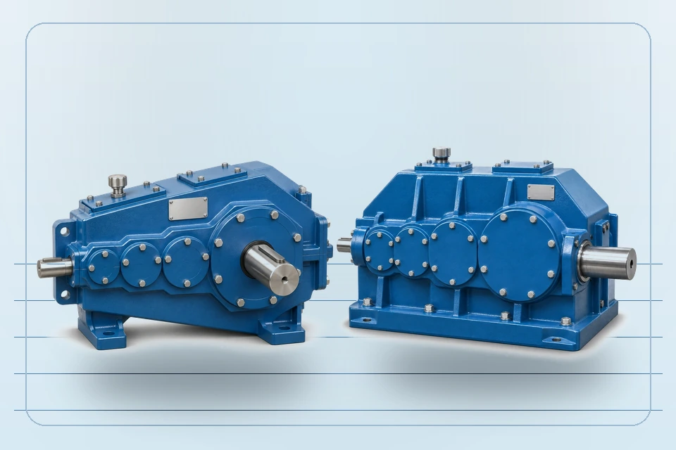
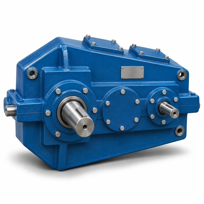
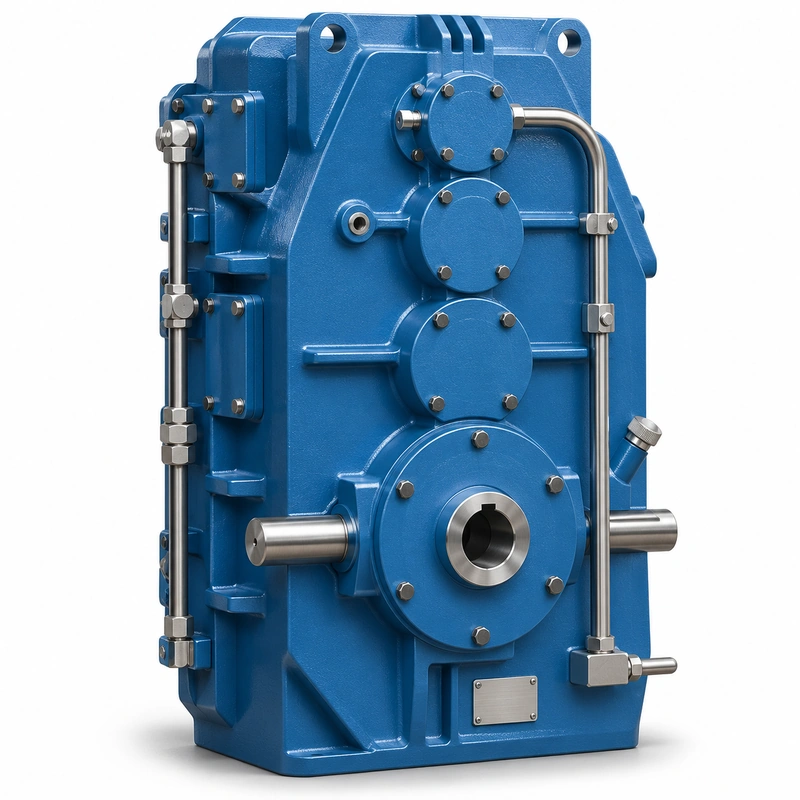
QY hardened crane gearboxes
Compare three-support and foot-mounted arrangements where the gearbox housing must match an existing support or foundation layout.

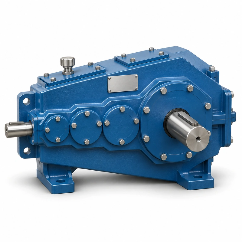
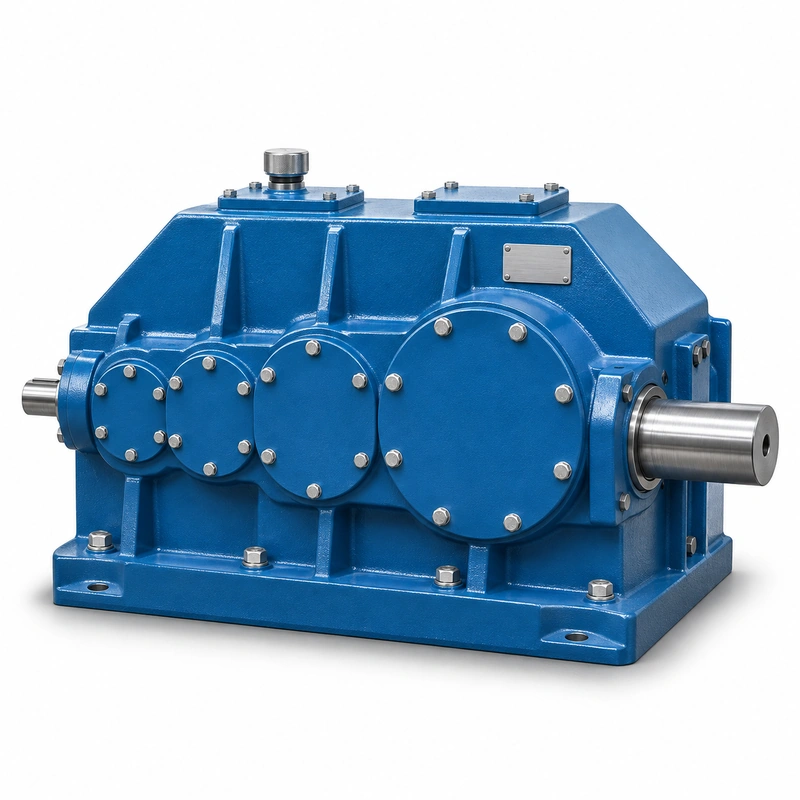
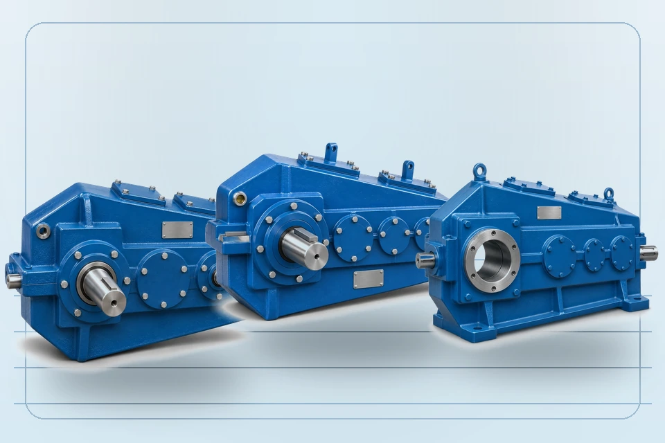
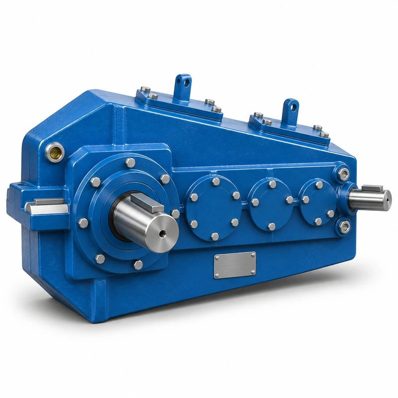
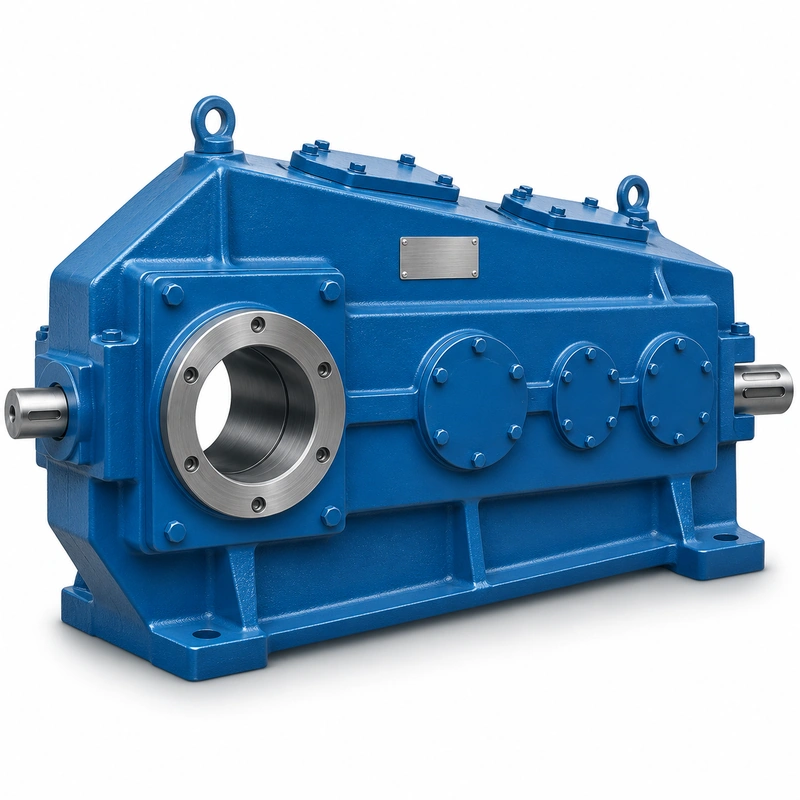
QJY hardened gear reducers
Choose by reduction stage, housing format and solid- or hollow-shaft connection before checking the ordered frame size.
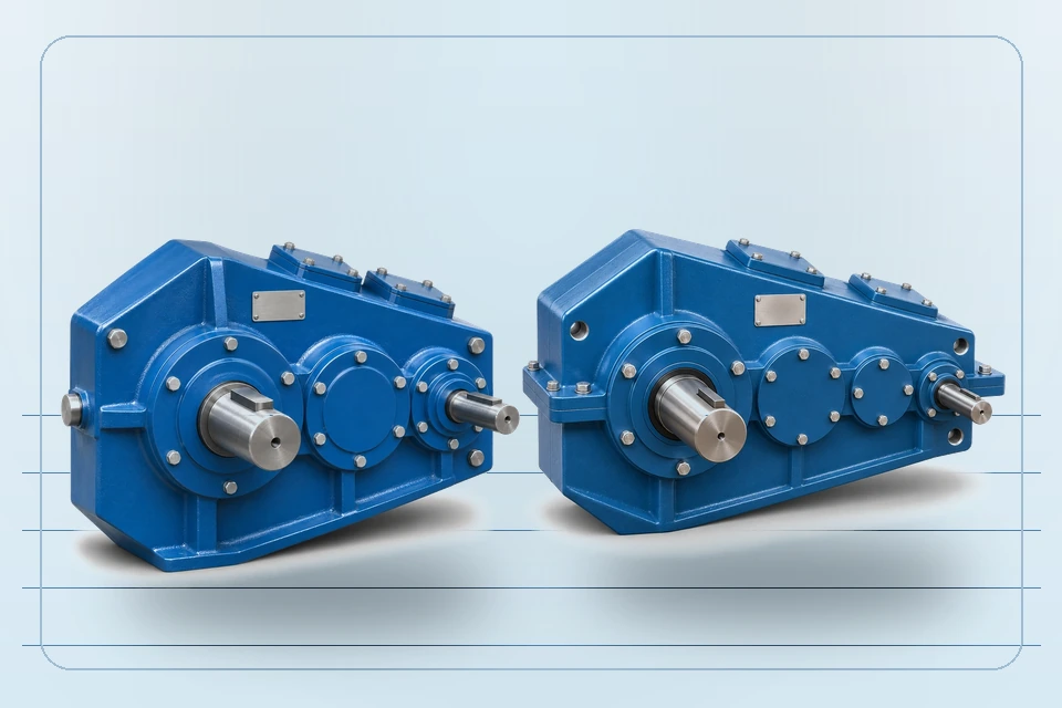
QJR / QJS medium-hardened reducers
Explore medium-hardened gear reducer families with different nominal reduction ranges and arrangement requirements.
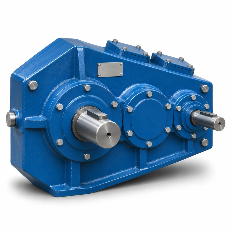
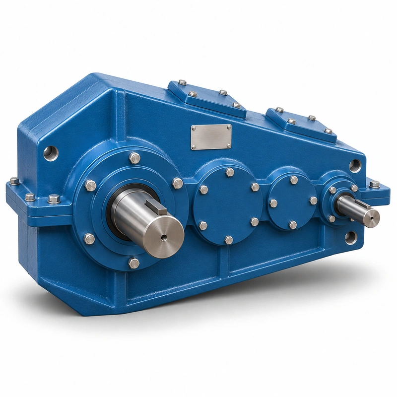
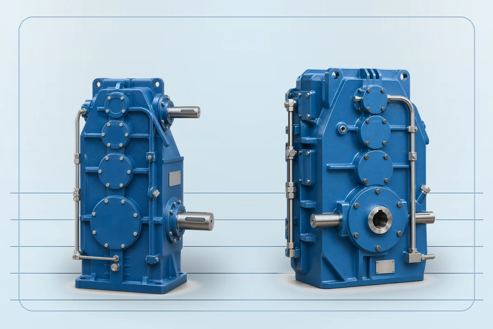
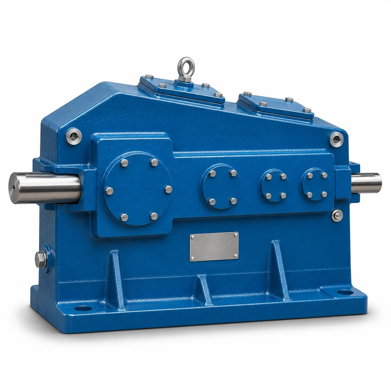
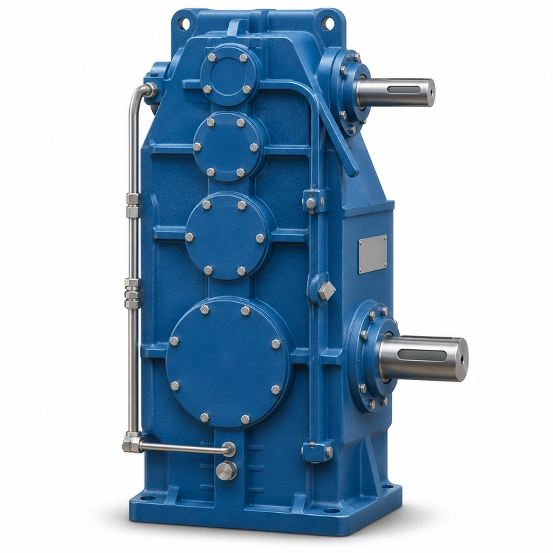
Vertical & shaft-mounted crane reducers
Review the vertical QJ-L arrangement and the shaft-mounted QJ-T configuration without treating their interfaces as interchangeable.
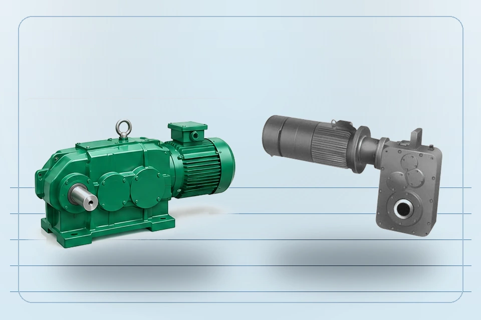
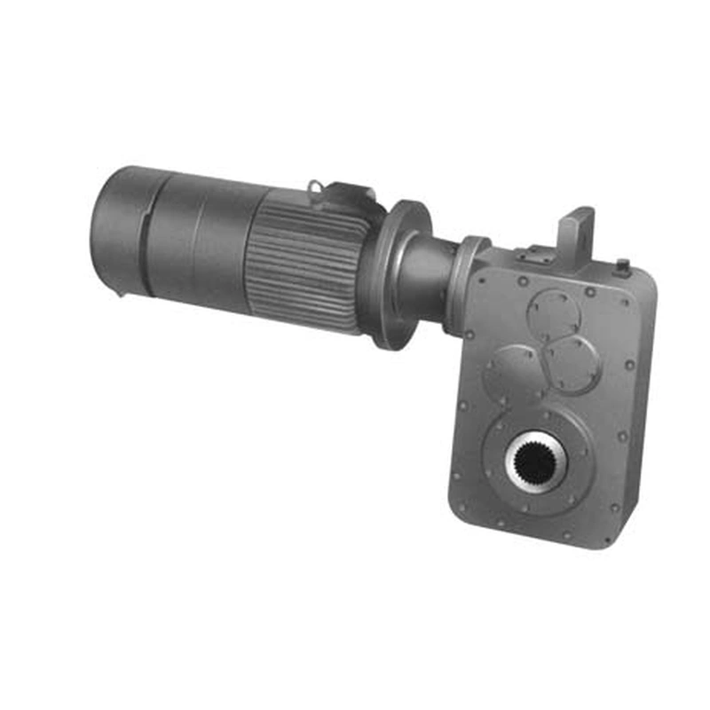
QS / QSC integrated crane gearmotors
Consider a combined motor-and-reducer unit when overall drive packaging, electrical input and output connection must be specified together.
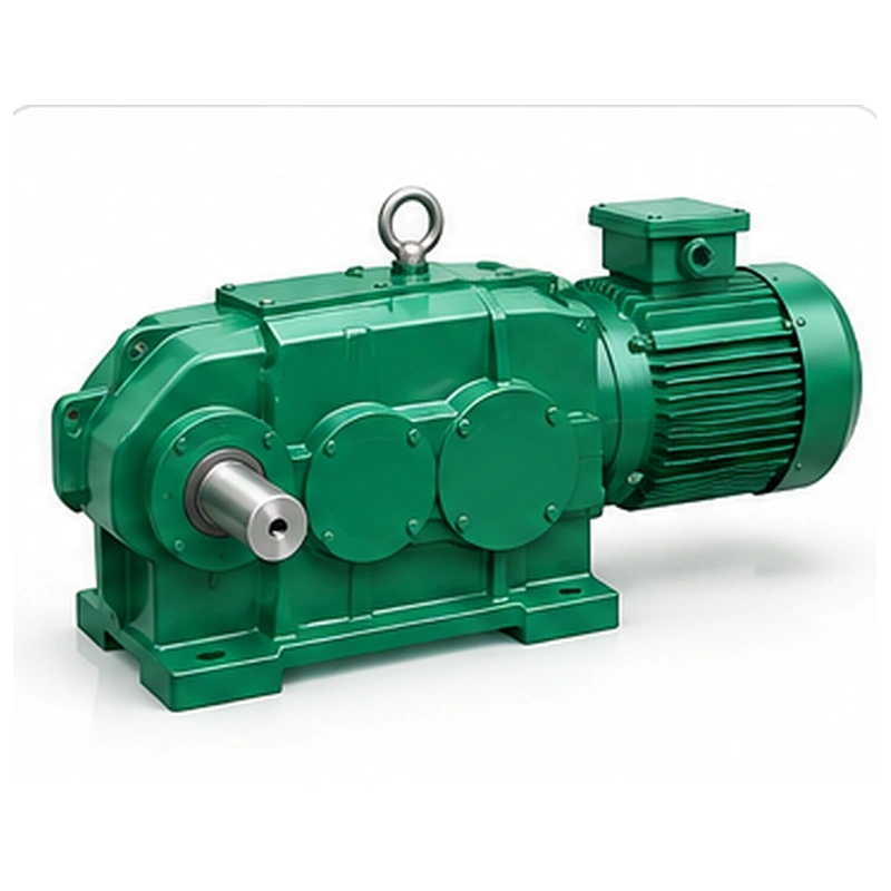
ZLC, point-line & special-purpose reducers
Explore ZLC cylindrical reducers, DQJ/DQJD support variants and project-specific A1570, J174GA-1000 and J38GA850 assemblies. Select by the original interface and required duty.
Product images are visual references; interface dimensions and final supply configurations must be checked against the relevant model drawing.
Explore ZLC, Point-Line & Project Gear Reducers
Compare these additional reducer designs by housing geometry, supported mounting arrangement and shaft interface. For replacement projects, begin with the original dimensioned drawing and operating duty.
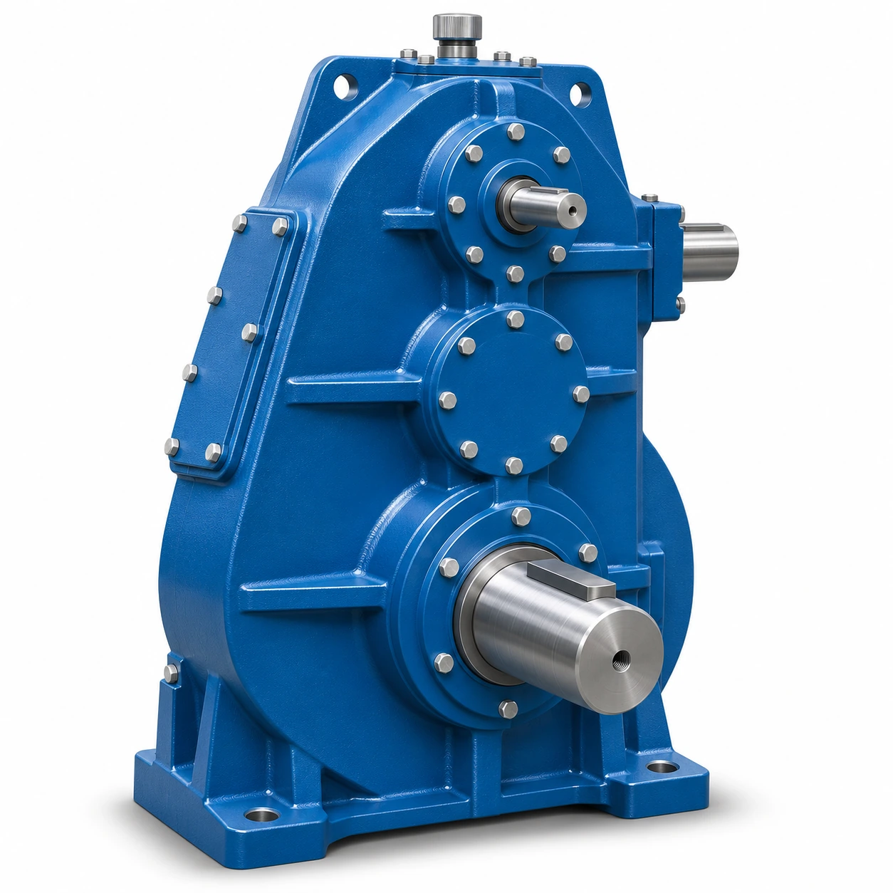
EP-ZLC Cylindrical Crane Gear Reducer
A cylindrical crane reducer series covering ZLC600, ZLC750 and ZLC850. Compare the required ratio, mounting envelope, input/output shafts and foundation dimensions before selection.
View technical details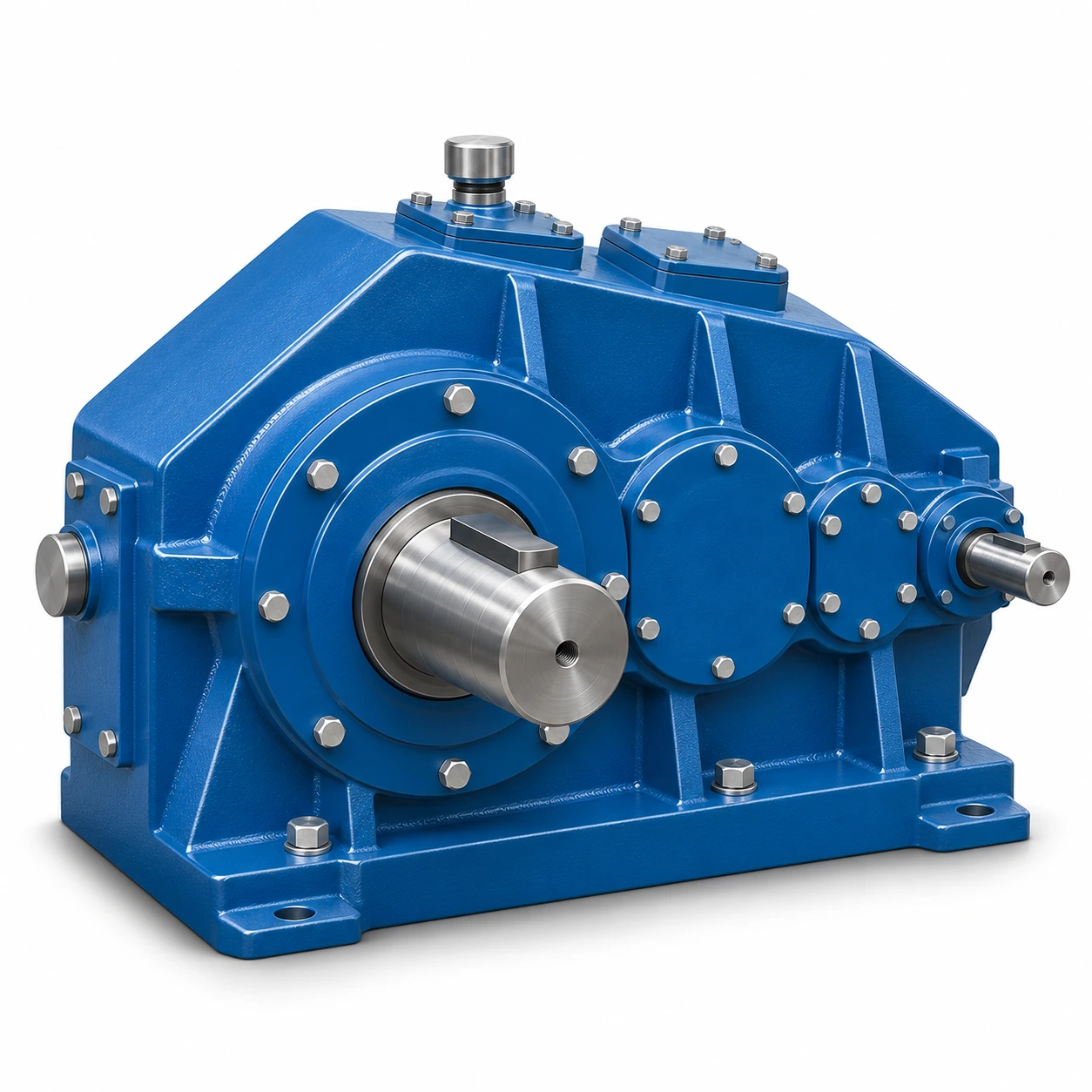
EP-DQJ/DQJD Point-Line Meshing Crane Gear Reducer
Point-line meshing reducer variants with distinct support schemes: DQJ three-point-supported versions and DQJD foot-mounted versions. Check the mounting configuration and P, H or C output interface.
View technical details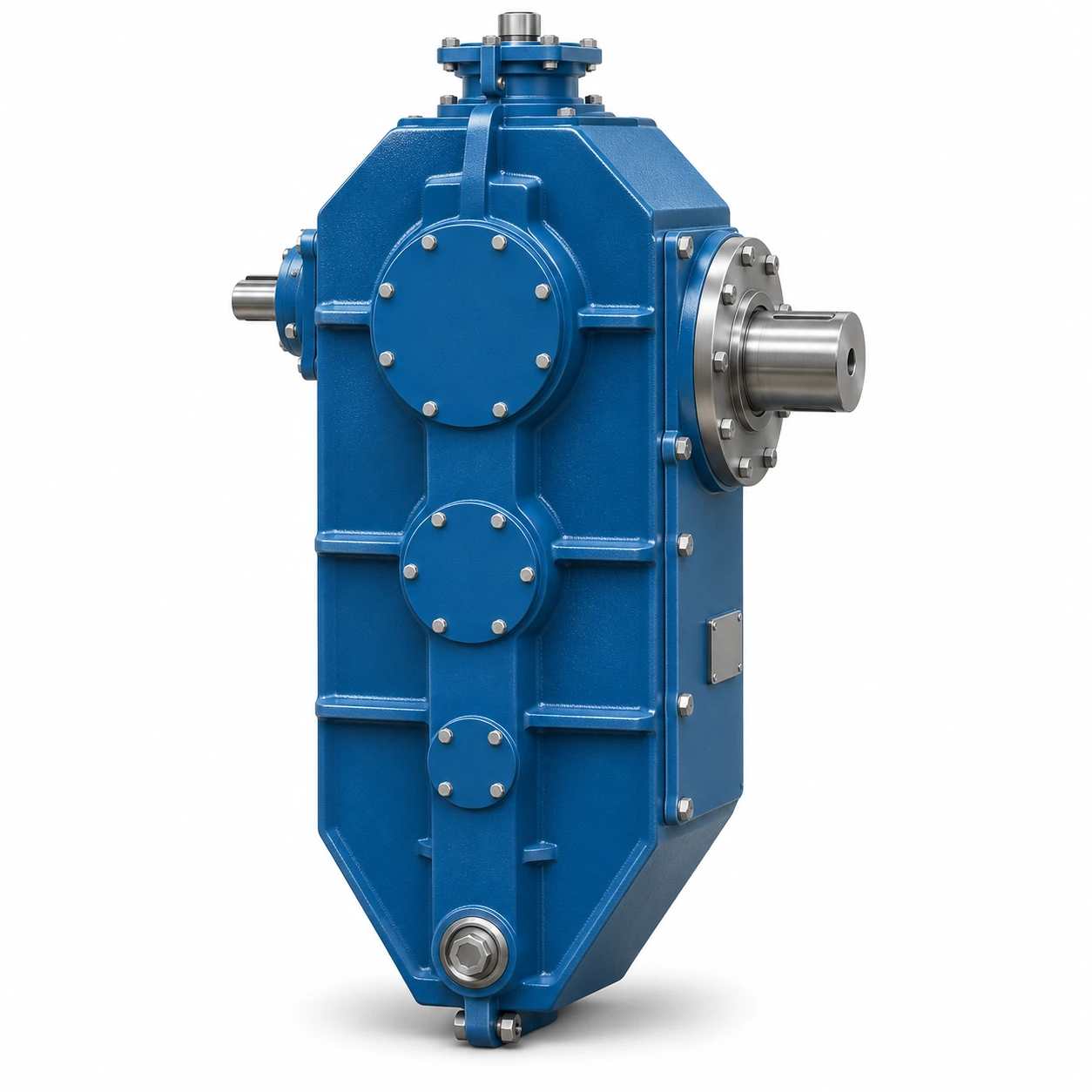
EP-A1570 Heavy-Duty Cylindrical Gear Reducer
A1570 cylindrical reducer assembly for projects where housing geometry, shaft connection and mounting dimensions must be checked against the original equipment drawing.
View technical details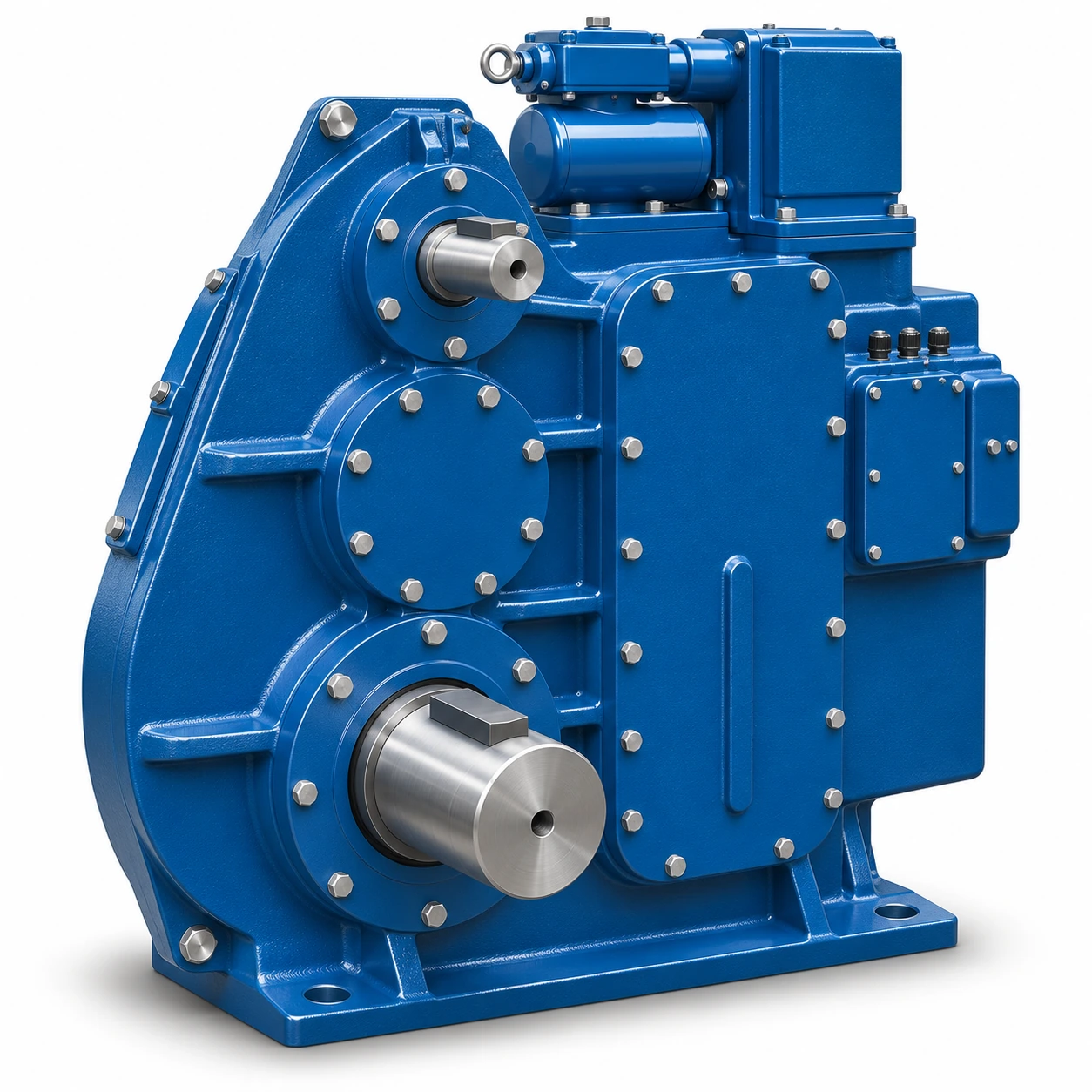
EP-J174GA-1000 Open-Gear Crane Reducer Assembly
An open-gear crane reducer assembly with multiple ratio and mounting arrangements. Confirm the exact transmission code, shaft position and adjoining drive layout for an application.
View technical details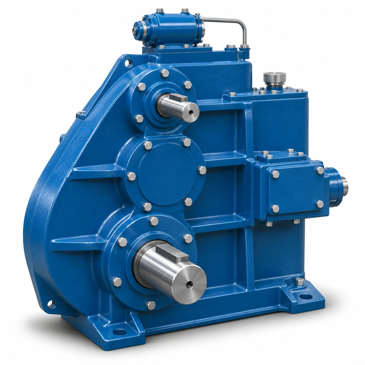
EP-J38GA850 Open-Gear Reducer Assembly
The J38GA850 open-gear reducer assembly has its own dimensional and mounting arrangements. Do not assume interchangeability with the J174GA-1000 unit merely because ratio listings overlap.
View technical detailsCompare Crane Gearbox Configurations
Use the arrangement and connection columns to narrow the choices before consulting the full dimensional drawing. A family label does not establish direct interchangeability between reducers.
| Model | Series | Construction | Key differentiator | Confirm before ordering | Details |
|---|---|---|---|---|---|
| EP-QY3S | QY hardened | Three-support housing | Three-Support Hardened Crane Gearbox | Mounting interface | View model → |
| EP-QY3D | QY hardened | Foot-mounted housing | Foot-Mounted Hardened Crane Gearbox | Foundation dimensions | View model → |
| EP-QJY2 | QJY hardened | Two-stage reduction | Two-Stage Hardened Crane Gear Reducer | Required ratio | View model → |
| EP-QJY3 | QJY hardened | Three-stage reduction | Three-Stage Hardened Crane Gear Reducer | Required ratio | View model → |
| EP-QJYD3 | QJY hardened | Three-stage / foot-mounted | Foot-Mounted Three-Stage Hardened Crane Gearbox | Base and shaft layout | View model → |
| EP-QJYA3 | QJY hardened | Three-stage / hollow output | Hollow-Shaft Three-Stage Hardened Crane Gearbox | Mating shaft geometry | View model → |
| EP-QJR | QJR / QJS | Medium-hardened gearing | Medium-Hardened Crane Gear Reducer | Operating ratio | View model → |
| EP-QJS | QJR / QJS | Higher reduction range | High-Reduction Medium-Hardened Crane Gearbox | Output speed | View model → |
| EP-QJ-L | Vertical / shaft-mounted | Vertical, base-mounted | Vertical Crane Gear Reducer | Vertical clearances | View model → |
| EP-QJ-T | Vertical / shaft-mounted | Shaft-mounted connection | Shaft-Mounted Crane Reducer | Shaft fit and restraints | View model → |
| EP-QS | Integrated gearmotors | Integrated drive assembly | Integrated 3-in-1 Crane Gearmotor | Motor and output interface | View model → |
| EP-QSC | Integrated gearmotors | Vertical integrated assembly | Vertical Integrated Crane Gearmotor | Motor and connection | View model → |
| EP-ZLC | ZLC series | Cylindrical gear reducer | ZLC600 / ZLC750 / ZLC850 model options | Ratio, shafts and foundation | View model |
| EP-DQJ/DQJD | Point-line meshing | Three-point or foot-mounted | DQJ / DQJD mounting variants | Support layout and P/H/C shaft end | View model |
| EP-A1570 | Project reducers | Cylindrical reducer assembly | A1570 project-specific geometry | Dimensions, ratio and duty | View model |
| EP-J174GA-1000 | Project reducers | Open-gear reducer assembly | A1000 assembly and ratio choices | Ratio code and installation interface | View model |
| EP-J38GA850 | Project reducers | Open-gear reducer assembly | A850 installation geometry | Housing and shaft connections | View model |
Nominal family reduction references include QJY2 at 6.3–20, QJY3 at 20–100, QJR at 10–31.5, and QJS at 40–200. These are series-level ranges; exact combinations, rated torque and installation constraints depend on the ordered configuration.
How to Choose a Crane Gearbox
The best starting point is a verified duty and interface specification, not only a gearbox model name.
Define the mechanism
Identify hoisting, bridge travel, trolley travel or another function. Record the load, working cycle, acceleration and braking sequence.
Determine drive duty
Use input and output speeds for the target ratio, then evaluate output torque, peak loads, service requirements and any reverse loading.
Measure connections
Confirm housing space, support points, bolt locations, shaft diameter, coupling details, orientation and access for installation.
Review the configuration
Compare drawings, motor and brake arrangement, lubrication, environmental conditions and maintenance access before finalizing.
Send the existing model reference and installation dimensions for a configuration-focused review.
Mounting & Output Shaft Configurations
Support geometry, mounting feet and shaft interfaces can differ even between reducers with similar ratios. Review the connections shown below and compare them with the drawing for the ordered model.
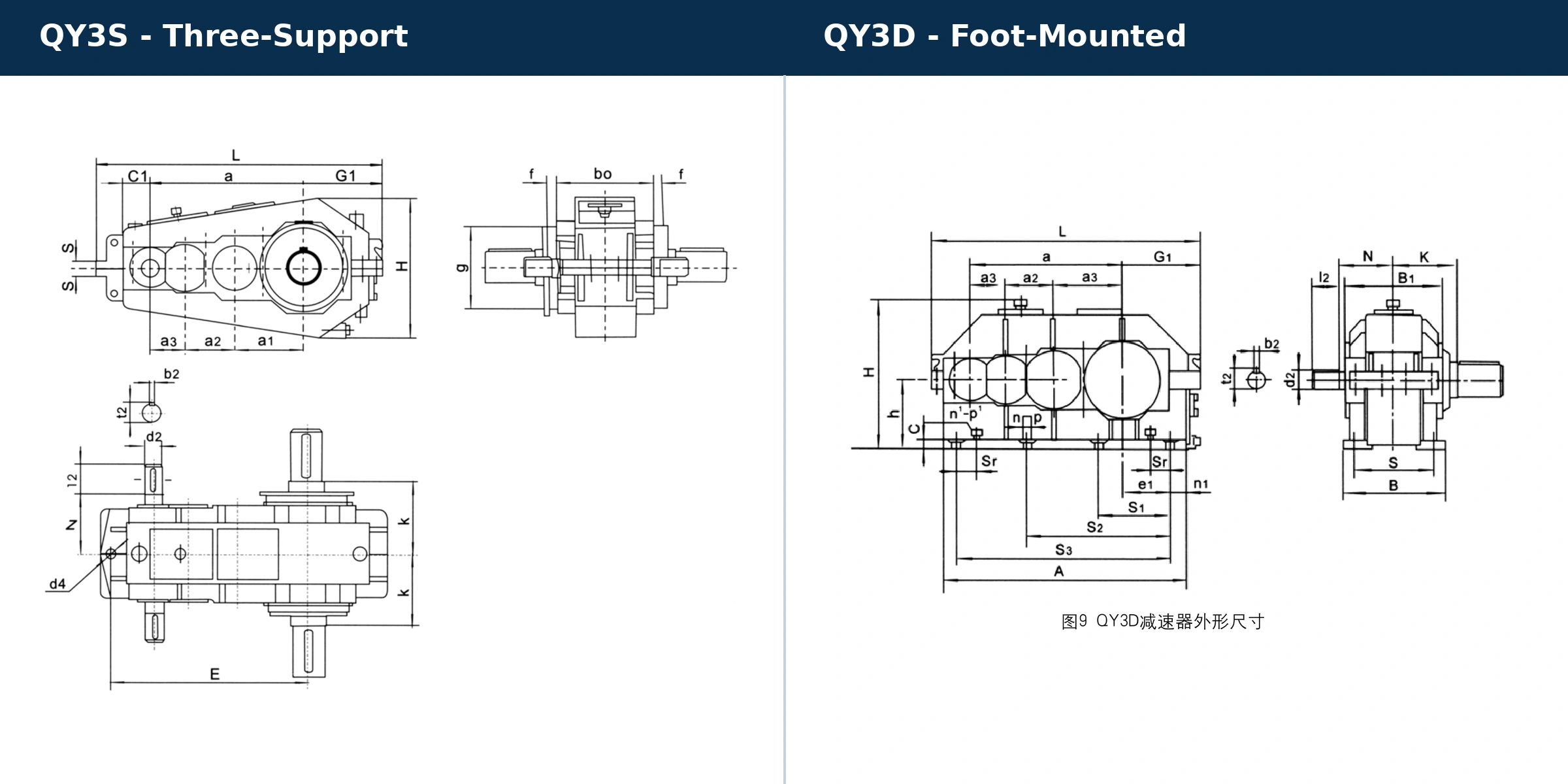
Three-support versus foot-mounted arrangements
Review EP-QY3S and EP-QY3D as distinct support concepts. Check bolt location, housing clearances, output elevation and the way the surrounding structure carries gearbox loads.
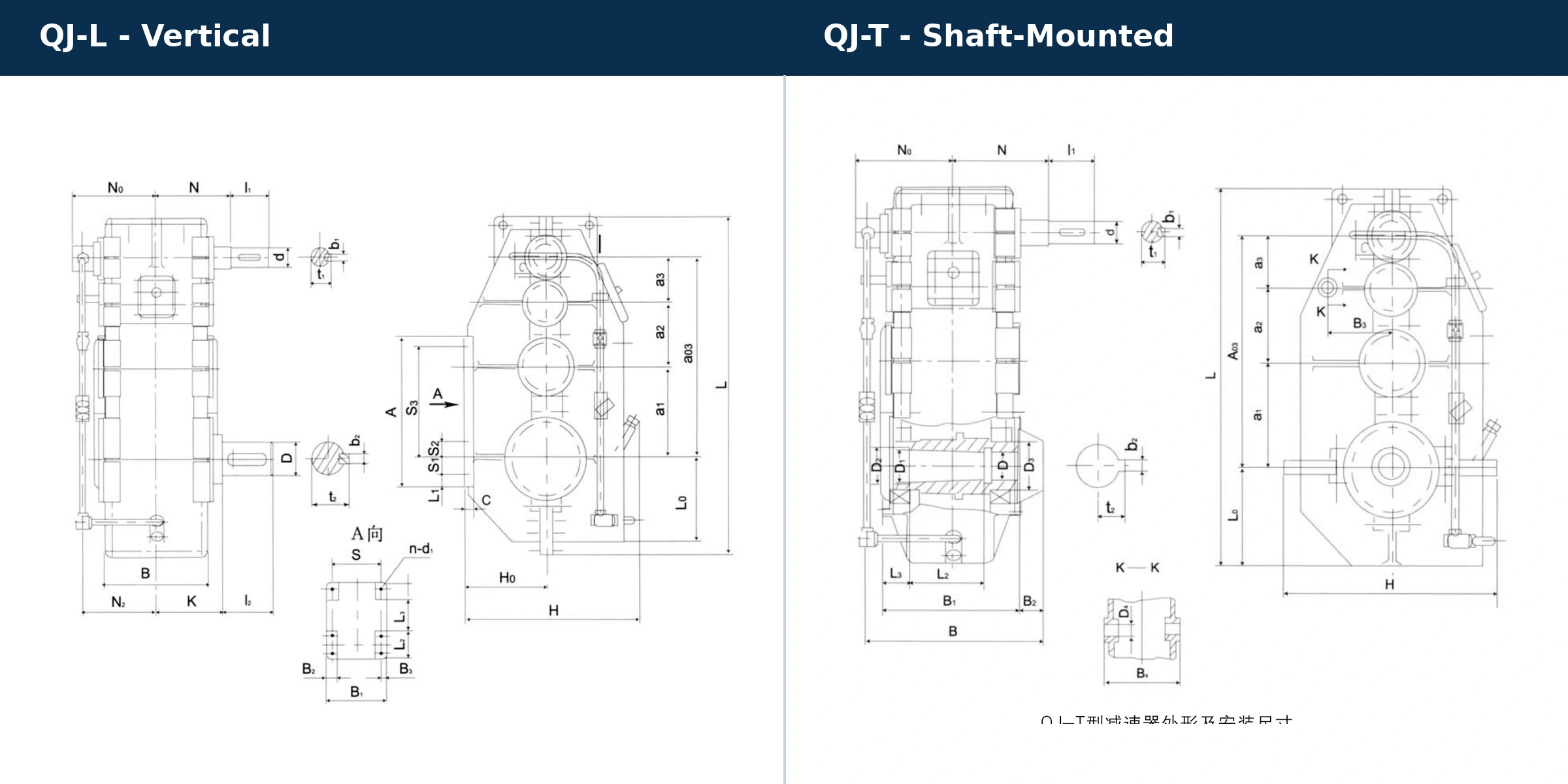
Vertical base and shaft-mounted reducer interfaces
EP-QJ-L and EP-QJ-T are alternatives in arrangement, not automatically interchangeable units. Compare the output connection, axial location, available supports and access to assembly hardware.
Hollow-shaft output and mating-shaft fit
A hollow-output configuration requires attention to the mating shaft, engagement, key or spline specification and axial retention. EP-QJYA3 is the relevant reference within the QJY range.
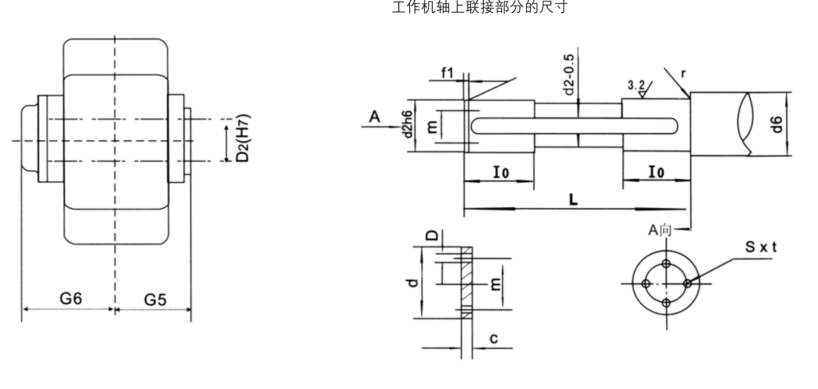
DQJ three-point support and DQJD foot mounting
The DQJ variants use a three-point-supported arrangement; DQJD variants use foot mounting. Check the support reactions, mounting positions, available orientation and the output end identified as P, H or C before specifying a reducer. See EP-DQJ/DQJD specifications for configuration-specific details.
Where Crane Gear Reducers Are Used
Selection requirements change with the crane mechanism. The examples below show the drive environment and the engineering questions that usually matter.


Overhead crane drives
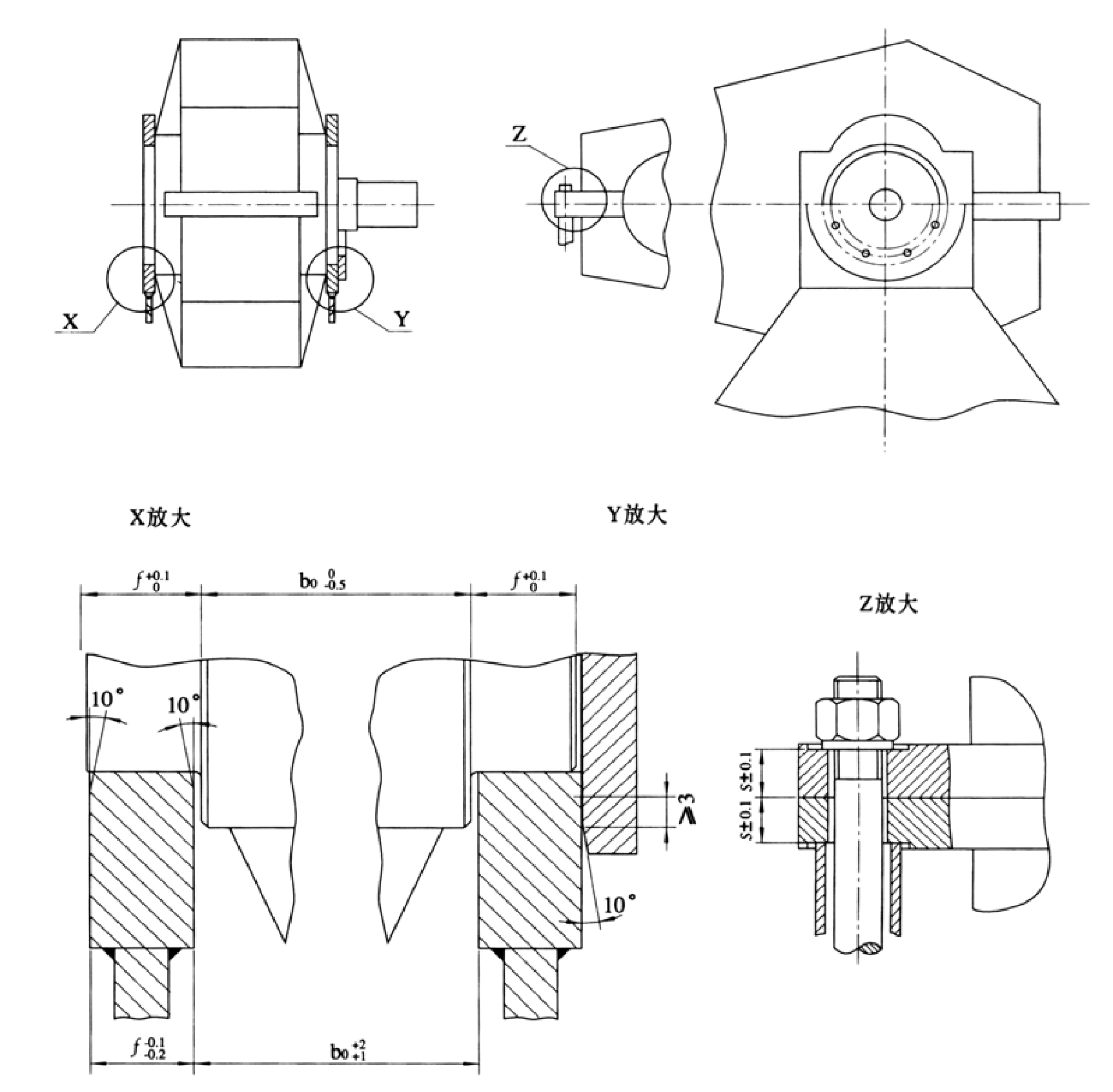
A gearbox selection for an overhead crane begins with the specific hoisting or travel duty, starts per hour, expected service load and available installation envelope.
Gantry crane drives
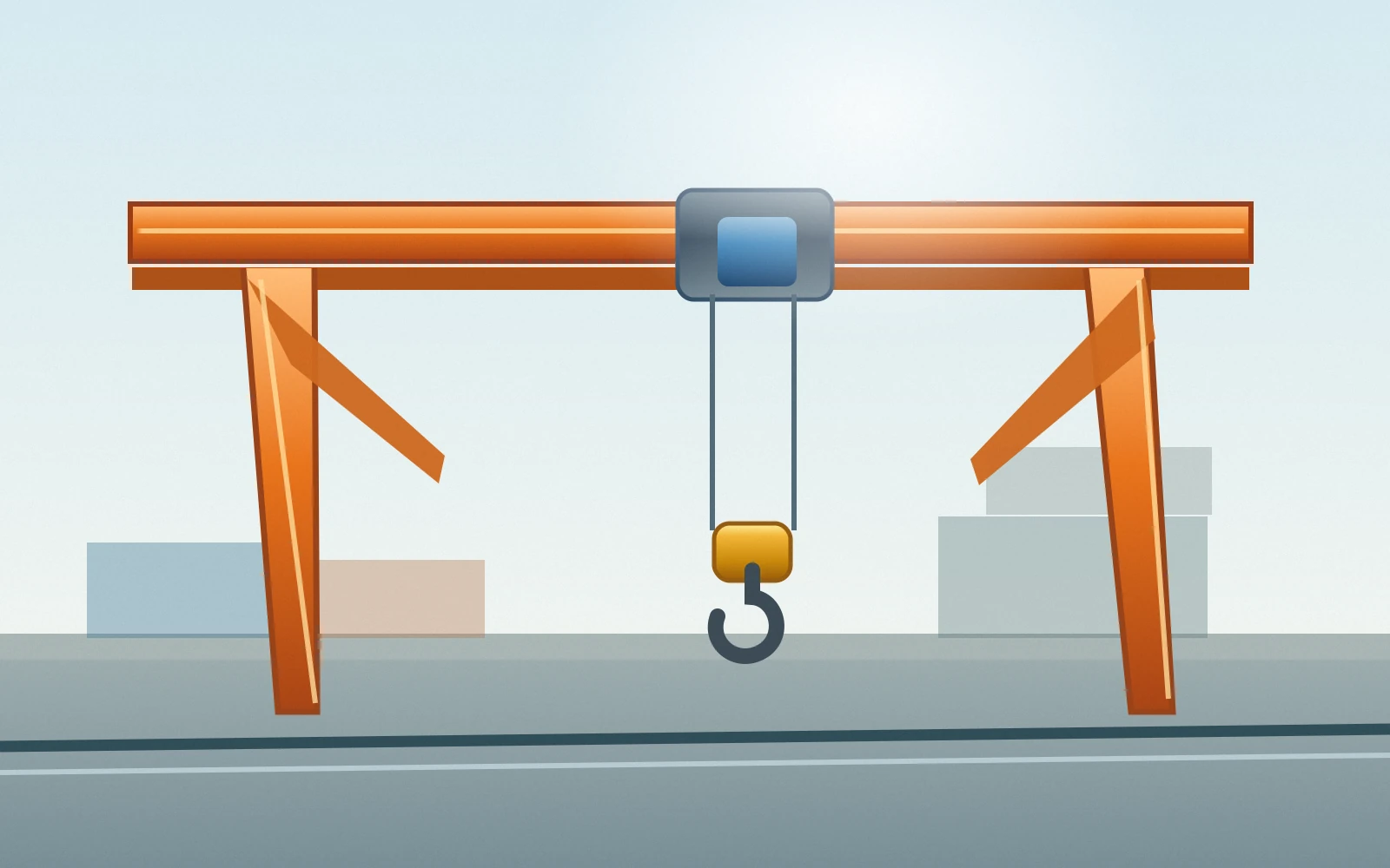
Gantry mechanisms add questions about outdoor exposure, runway alignment, space around the drive and how the output connects to the wheel or drum.

Hoisting mechanisms
For hoisting, give the lifting load, drum or output speed, braking arrangement and duty classification before choosing reduction stages or rated output torque.

Crane travel mechanisms
Travel-drive inquiries should include wheel diameter, desired travel speed, acceleration, start-stop frequency and the mechanical transmission between reducer and wheel.
Application imagery illustrates equipment environments. It does not represent a specific installed gearbox configuration or a customer installation record.
Planning a Crane Gearbox Replacement or Retrofit?
When replacing an existing unit, a matching input power or nominal ratio is insufficient. The mechanical connection, load rating and control arrangement must all be reviewed.
Check the installed gearbox
- Overall length, height, width and available installation envelope.
- Mounting-hole pitch, support locations and base orientation.
- Input and output shaft geometry, keyways, splines and coupling.
- Rotation direction, ratio, output speed and reversing duty.
Review operating constraints
- Continuous and peak torque, shock loading and working cycle.
- Motor interface, electrical supply and brake requirements.
- Permitted output radial and axial loads and bearing conditions.
- Lubrication, temperature, installation accessibility and guarding.
Provide a clear drawing or nameplate photo alongside the actual machine requirements. That helps establish whether a standard configuration or project-specific engineering review is needed.
Crane Gearbox Selection FAQ
Practical answers about gear reducer families, mounting connections and replacement information.
What is the main difference between QY and QJY crane gearboxes?
QY and QJY are separate crane-reducer product families. Within these families, the mounting support, housing pattern, reduction stages and output connection determine whether a model is relevant to your installation. Select from the installation drawing and operating duty rather than assuming similar model names indicate a direct replacement.
Should I use a two-stage or a three-stage crane gear reducer?
Start with the required input and output speeds to calculate the overall ratio. QJY2 is a two-stage family, while QJY3 is a three-stage family. Then check torque, duty and mounting constraints; a reduction stage count alone does not determine suitability for the machine.
Is a hollow-shaft gearbox interchangeable with a solid-shaft gearbox?
Not automatically. Hollow-shaft models such as EP-QJYA3 need matching shaft diameter, connection geometry, engagement length and retention arrangement. A solid-shaft reducer may require a different coupling or support scheme. Send the mating-shaft drawing and installation envelope to establish a feasible configuration.
What separates QJR from QJS models?
The QJR and QJS families are differentiated in the product range by their nominal reduction range and related series configurations. QJS is the higher-reduction series in this collection. The final selection should still be checked against frame size, torque, input speed and operating conditions.
How do QJ-L and QJ-T mounting arrangements differ?
QJ-L is presented as a vertical reducer with a base mounting arrangement; QJ-T uses a shaft-mounted configuration. Foundation restraints, axial location, shaft fit and surrounding clearances may therefore differ significantly. Do not reuse one family's mounting drawing for the other.
When is an integrated crane gearmotor worth considering?
QS and QSC are integrated motor-and-reducer choices when a coordinated drive package is useful. Include motor power, supply, braking requirements, reduction ratio, mounting orientation and output-interface information in the inquiry. Exact motor configuration and operating suitability must be confirmed for the project.
What should I provide for a replacement gearbox quotation?
A useful inquiry includes an existing model or nameplate photo, general arrangement drawing, overall and shaft dimensions, bolt-hole pattern, input and output speed, output torque or applied load, mounting orientation, working cycle and quantity. Where available, include the motor and brake data as well.
How do DQJ and DQJD point-line meshing reducers differ?
DQJ and DQJD share a point-line meshing reducer family but differ principally in mounting support. DQJ variants use a three-point-supported connection; DQJD variants are foot-mounted. Choose the required support and output arrangement from the drawing rather than treating the two as direct substitutes.
How should I compare ZLC, A1570, J174GA-1000 and J38GA850 for a replacement?
Start by identifying the original reducer model and confirming the ratio, shaft ends, mounting dimensions, available envelope and operating load. ZLC includes several frame sizes; A1570, J174GA-1000 and J38GA850 are individual project reducer references with separate installation geometry. Similar nomenclature does not prove interchangeable construction.
Need a Crane Gearbox That Fits Your Machine?
Share your operating requirements, existing model, dimensional drawing or drive arrangement with Ever Power. Our team can review the relevant crane reducer options and discuss configuration, documentation and quotation requirements for your inquiry.