


EP-QJ-T Shaft-Mounted Crane Reducer is specified for shaft-supported installation, axial retention and torque reaction. The QJ-T crane reducer uses a shaft-mounted arrangement that calls for a different interface check from a conventional foot-mounted gear unit. The dimensional schedule defines input and output geometry, overall size, installation features and mass for QJ-T140 through QJ-T400. These parameters describe how the reducer connects to the machine, not just the space occupied by a steel housing. A machine shaft may fit the nominal diameter but lack the necessary usable engagement or retention features.
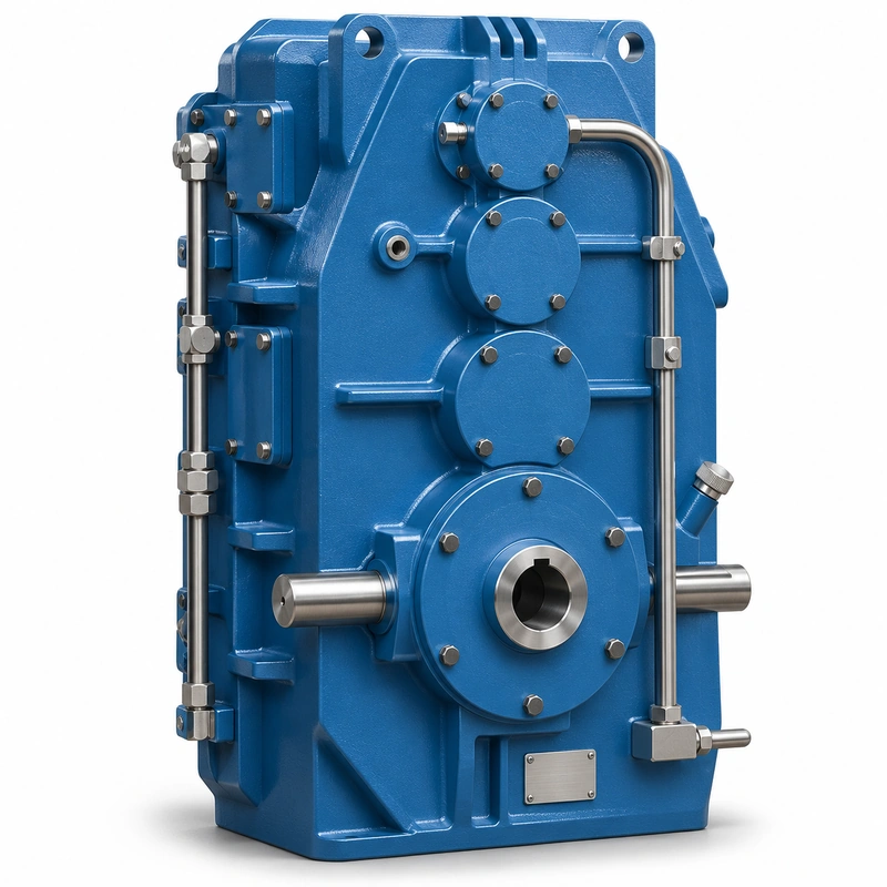
The housing support and shaft connection must be considered together because the gearbox torque reaction has to be transferred safely to the crane structure. Any proposed change to that path, including a new torque arm or altered bracket, deserves an engineering review. Buyers should distinguish QJ-T from QJ-L: the two names are not alternative captions for the same drawing. Their detailed output geometry and mounting arrangements differ.
Mounting and operating behavior of EP-QJ-T
Torque reaction arrangement
A mounted reducer still experiences casing reaction as load torque changes. Define the bracket, torque arm or support through which it is resisted. Reversing can alternate the reaction direction, which may affect pin wear or clearances. A rigid restraint at the wrong location may transfer unwanted loads into the gearbox bearings.

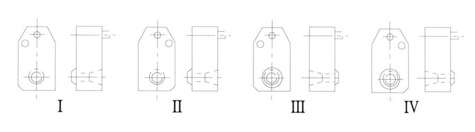
Shaft engagement
Measure the mating shaft from a fixed datum and record diameters, length, shoulders, keyways and any fit features. Include actual measured values if an old shaft is being reused. Wear, burrs or corrosion can prevent complete seating even when a basic nominal diameter matches.
Model mass and handling
The listed QJ-T dimensions and weights vary substantially by frame; the schedule ranges from approximately 76 kg to 938 kg. Prepare lifting and installation plans using the exact selected unit mass, not the family minimum. Protect shaft sealing surfaces and ensure the support rig holds the gearbox until retention is secure.
QJ-T specification and model identification
QJ-T Shaft Mounted Crane Reducer selection is defined by the combination of family construction, operating point and machine interfaces. The following data identifies the documented product family; a specific configuration must still be checked against its dimensional drawing and duty schedule.

| Parameter | Series-level reference |
|---|---|
| Series frames | QJ-T140, 170, 200, 236, 280, 335 and 400 |
| Connection | Dedicated shaft-mounted/tapered-output configuration shown in the T drawing |
| Size data | Input and output shaft geometry by frame |
| Weight | 76–938 kg across listed frame sizes |
| Ratio selection | Confirm series ratio and exact gearbox configuration |
Machine shaft interface
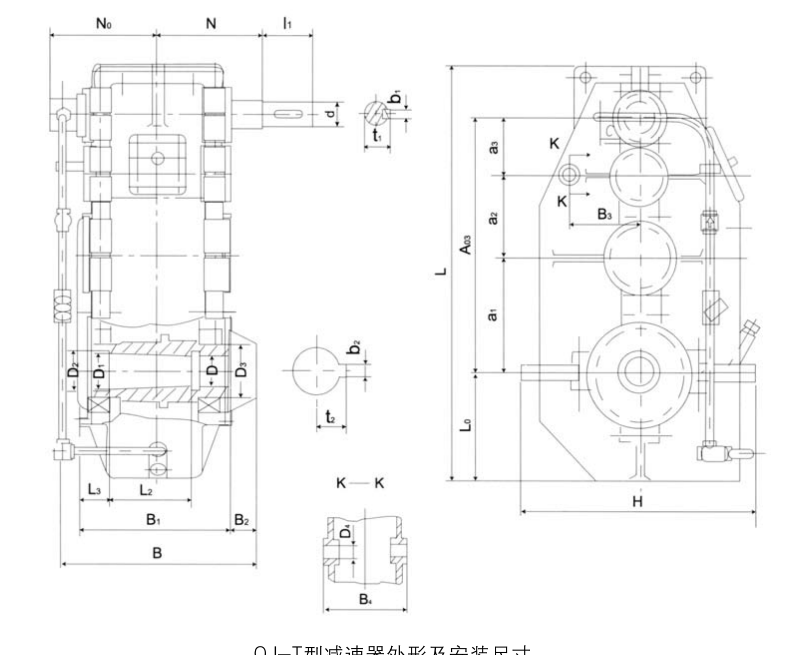
| Model | a1 | a2 | a3 | a03 | d | l1 | N | b1 | t1 | D | D1 | D2 | D3 | L2 | L3 | b2 | t2 |
|---|---|---|---|---|---|---|---|---|---|---|---|---|---|---|---|---|---|
| QJ-T140 | 140 | 100 | 71 | 311 | 20 | 50 | 120 | 6 | 22.5 | 40 | 50 | 55 | 70 | 105 | 50 | 14 | 26.2 |
| QJ-T170 | 170 | 118 | 85 | 373 | 25 | 50 | 135 | 8 | 28 | 50 | 60 | 65 | 80 | 105 | 55 | 16 | 31.7 |
| QJ-T200 | 200 | 140 | 100 | 440 | 28 | 60 | 180 | 8 | 31 | 55 | 65 | 70 | 90 | 105 | 60 | 18 | 34.3 |
| QJ-T236 | 236 | 170 | 118 | 524 | 35 | 80 | 210 | 10 | 38 | 70 | 85 | 90 | 120 | 155 | 70 | 22 | 44 |
| QJ-T280 | 280 | 200 | 140 | 620 | 40 | 110 | 235 | 12 | 43 | 75 | 95 | 100 | 130 | 205 | 75 | 22 | 47.8 |
| QJ-T335 | 335 | 236 | 170 | 741 | 45 | 110 | 255 | 14 | 48.5 | 90 | 110 | 120 | 160 | 205 | 85 | 28 | 56.3 |
| QJ-T400 | 400 | 280 | 200 | 880 | 55 | 110 | 285 | 16 | 59 | 100 | 120 | 130 | 180 | 255 | 105 | 28 | 60.03 |
Overall envelope and mass
| Model | H | B | B1 | L | L0 | N0 | B2 | B3 | B4 | D4 | Mass kg |
|---|---|---|---|---|---|---|---|---|---|---|---|
| QJ-T140 | 324 | 256 | 214 | 526 | 135 | 103 | 35 | 85 | 150 | 25 | 76 |
| QJ-T170 | 376 | 281 | 239 | 618 | 160 | 115 | 35 | 105 | 170 | 25 | 108 |
| QJ-T200 | 426 | 333 | 274 | 715 | 185 | 133 | 50 | 135 | 200 | 25 | 153 |
| QJ-T236 | 510 | 387 | 328 | 854 | 220 | 158 | 50 | 155 | 245 | 28 | 247 |
| QJ-T280 | 580 | 460 | 368 | 995 | 255 | 277 | 65 | 190 | 270 | 28 | 364 |
| QJ-T335 | 689 | 524 | 436 | 1196 | 310 | 307 | 65 | 225 | 330 | 32 | 593 |
| QJ-T400 | 807 | 624 | 526 | 1396 | 365 | 352 | 75 | 280 | 390 | 40 | 938 |
Axial location and restraint
Clarify where the reducer is held axially and whether the machine shaft has shoulders, retaining bolts or other position controls. The permissible axial-force path cannot be guessed from the outline drawing. Where thermal expansion changes shaft length, the support arrangement needs to accommodate movement in the intended direction.
Gear ratio and braking
The mechanical output speed must suit the crane mechanism. Obtain the exact ratio for the selected configuration and verify motor and brake coordination. A high-ratio gearbox does not replace the independent safety or holding functions required by the crane design.
Coupling elimination tradeoffs
A direct shaft-mounted connection may reduce the need for a separate output coupling, but it changes the servicing sequence. Check whether the gearbox can slide clear of the work shaft with the adjacent guard and machine equipment in place. Include extraction access in the retrofit design.
Inspection strategy
Observe shaft-to-housing interfaces for fretting, leaks or movement after commissioning. Check retaining hardware and reaction arm connections under representative reversing cycles. Inspection should cover the crane mounting system as well as the gearbox internals because wear at the interface can influence transmission life.
Shaft-supported drive integration
For an EP-QJ-T installation, the main decision concerns shaft-supported installation, axial retention and torque reaction. Retaining and withdrawing the reducer from the work shaft belong in the installation plan, not only the service manual. The best starting point is the actual machine arrangement, the operating load and the requested output speed.
Select
Confirm the true mechanical work point for QJ-T Shaft Mounted Crane Reducer: input speed, demanded output torque and the dynamic events that govern component loading.
Measure
Use the QJ-T dimensional drawing to validate the installation envelope, shaft interfaces, mounting features and clearances on the actual machine.
Integrate
Match the selected drive with the connected motor, brake, coupling and supporting crane structure. Treat fit and control as one application.
Maintain
Plan access for lubrication, seals, inspection and removal. A compatible gearbox should also be practical to service after the crane is installed.
Replacing a shaft-mounted mechanism
Inspect the machine shaft for wear and measure every engagement feature. A new QJ-T reduction unit may need a reaction support redesign if the old bracket is distorted. Define installation and extraction access before signing off the replacement.
Machine-shaft drive applications
- Crane mechanisms built around a supported work shaft: describe the working load and mechanical interface before defining the reducer or gearmotor variant.
- Retrofits where the original machine shaft must remain installed: describe the working load and mechanical interface before defining the reducer or gearmotor variant.
- Industrial material-handling drives requiring a specialized output seat: describe the working load and mechanical interface before defining the reducer or gearmotor variant.
Shaft-mounted reducer order inputs
- Work-shaft fit and straightness: include the appropriate drawing, measured value, operating cycle or connection detail.
- Male shaft geometry and tolerance: include the appropriate drawing, measured value, operating cycle or connection detail.
- Gearbox axial retention method: include the appropriate drawing, measured value, operating cycle or connection detail.
- Torque-arm support sketch: include the appropriate drawing, measured value, operating cycle or connection detail.
- Selected qj-t frame mass: include the appropriate drawing, measured value, operating cycle or connection detail.
- Motor and actual gear ratio: include the appropriate drawing, measured value, operating cycle or connection detail.
- Driven shaft external forces: include the appropriate drawing, measured value, operating cycle or connection detail.
- Installation and removal clearance: include the appropriate drawing, measured value, operating cycle or connection detail.
Commercial enquiry for the QJ-T series
Ever Power can discuss model identification, interface drawings and practical order quantities for the QJ-T Shaft Mounted Crane Reducer. Confirmed product configuration, lead time and delivery terms belong in the quotation. Trial and mixed-model requests can be assessed against the total order value.
To compare related drive families, explore the industrial drive product range. The company overview explains the supplier context for engineering and procurement enquiries.
Frequently asked questions about EP-QJ-T
What differs between a QJ-T and a QJ-L reducer?
QJ-T uses its own shaft-mounted output and installation schedule; QJ-L has a separate vertical arrangement and dimensions. Do not transfer one drawing to the other.
Is QJ-T suitable for an existing work shaft without modifications?
Suitability depends on actual shaft dimensions, fits, retention, reaction restraint and applied load. Please provide a dimensioned machine-shaft drawing and a photograph of the installed assembly.
What lifting data do I need for QJ-T installation?
Use the selected frame weight, lifting-point locations, centre of gravity if confirmed, shaft withdrawal clearance and the approved handling plan. A generic family picture is not a lifting procedure.
How does a trial order work for a customized gearbox for EP-QJ-T?
For a suitable trial build, a new customer may request 1–5 samples. A 1–2-piece production order can sometimes be accommodated with a higher per-unit cost. Different gear-unit models may be combined in one commercial order if the overall minimum order value is around USD 1,500. Final MOQ depends on the configuration. For this product, quote preparation should also address shaft-supported installation, axial retention and torque reaction and the requested quantity.
What production schedule and Incoterms should be used for planning for EP-QJ-T?
Indicative production windows are 10–25 working days for standard units, 20–45 for customized components and 45–120 for project equipment. Confirm the date in the accepted quotation. EXW, FOB, CIF and DAP are commonly discussed; FCA, CFR, CPT, CIP and DDP can be reviewed for the actual destination and contract. Schedule confirmation follows review of the QJ-T interface and duty requirements.
Match the QJ-T shaft interface before ordering
Send the actual driven-shaft dimensions and the torque-reaction mounting arrangement for an EP-QJ-T quotation. A shaft-mount review helps avoid fit problems during installation.