


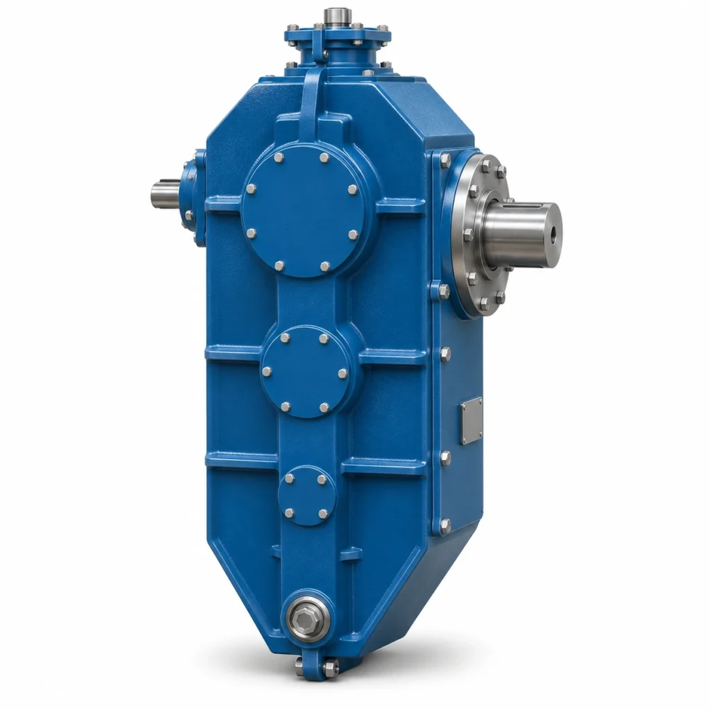
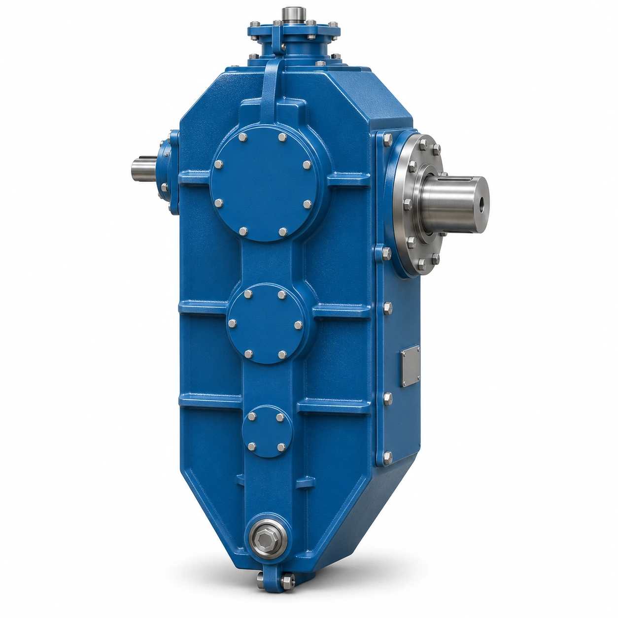
EP-A1570 Heavy-Duty Cylindrical Gear Reducer is a large industrial gearbox configuration for projects where the foundation, shaft interface and housing envelope need to be established from a dimensioned arrangement drawing. The A1570 designation identifies the reference product, but does not by itself specify a motor, reduction ratio, rated torque or completed installation package. For a replacement project, the first task is to determine whether the available mounting space and gearbox-to-machine connection can accept the reference housing geometry. For a new installation, the same information becomes a basis for engineering approval and procurement drawings.

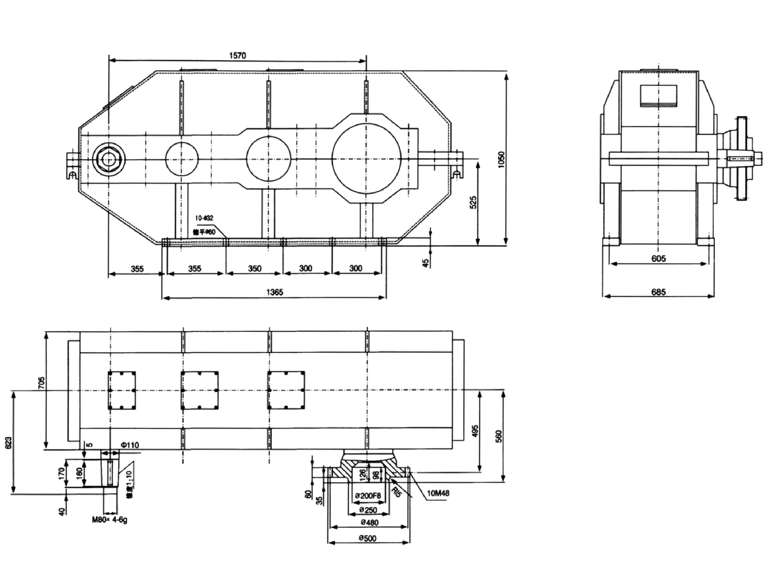
The arrangement drawing carries a 1570 mm labeled span and several installation dimensions.
The low-speed connection is shown with flange-related diameter and threaded-fastener annotations.
The provided sheet focuses on installation geometry, not a complete independent performance-rating schedule.
A1570 Enclosed Gear Reducer: Construction and Layout
The main elevation shows a long casing with a sequence of circular shaft and cover positions. An opposing view locates the outer edges of the casing and the machine-side connection. A third view places the projection and flange details relative to the housing faces. These views should be read together: isolated dimensions from one projection may describe a center-to-center interval rather than an overall envelope. The arrangement indicates a substantial cylindrical gear reducer assembly, but it does not independently disclose material certificates, current bearing part numbers or allowable overload levels.
A replacement evaluation starts with the transmission duty and physical arrangement as separate questions. The machine may have ample nominal space for a large gearbox yet still lack clearance for a coupling guard, lifting equipment, bearing inspection or motor connection. Conversely, a slightly different shell may be accommodated if the driven shaft centerlines and structural load path are proven correct. The intended gear train, output speed and applied loads should therefore be reviewed against an approved mechanical design rather than inferred from a similar exterior body.
A1570 Outline Drawing and Major Dimensions
The technical drawing should be placed next to the dimensions it explains. The labeled references include 1570 mm, 1065 mm, 685 mm and 605 mm, along with a detailed low-speed connection and inspection-hole features. These labels serve different purposes: some locate shaft stations, some describe the shell cross-section, and others dimension interfaces. Before using any of them for fabrication, identify the drawing datum and match each number to its arrows and projection.

| Drawing item | Reference callout | How it should be used |
|---|---|---|
| Longitudinal labeled span | 1570 mm | Confirm the indicated arrows and stations rather than treating it automatically as total overall length |
| Major vertical projection | 1065 mm | Check the exact face and datum in the principal elevation |
| Housing-width reference | 685 mm | Check against the available surrounding framework |
| Intermediate width/reference | 605 mm | Identify the component faces included in the dimension |
| Reference assembly mass | 4520 kg | Use for preliminary handling only; reconfirm the ordered configuration |
| Low-speed connection bore | Diameter 200 F8 shown | Confirm fit interpretation and mating component |
| Connection diameter labels | Diameter 250, 480 and 500 shown | Review flange, locating faces and bolt-circle relationship |
| Connection fastening | 10 x M48 shown | Validate thread depth, engagement and retaining design on the approved drawing |
Callout interpretation is not a manufacturing release. Verify datums, units and drawing revision for the actual supply specification.
Low-Speed Connection, Coupling and Retention Details
The most important interface on the A1570 drawing is the driven side. The connection area shows a stepped flange or hub profile with diameter labels, a fit-designated bore and a circular fastening pattern. A drawing review should distinguish the bore that locates the mating component from a bolt circle that only clamps it. When the assembly is subjected to reversing torque or shock, the designer should verify both the torque-transmitting feature and axial retention. Bolt size alone is not evidence that a connection can carry the machine load.
- Define the mating component datum: locate the shaft centerline, the face of contact and the direction of assembly.
- Verify the indicated diameter 200 F8 region against the matching bore or shaft, including tolerances and engagement.
- Review the diameter 250, 480 and 500 labels with the flange profile, fastener positions and available service access.
- Confirm the thread specification and engagement for all connection fasteners; do not substitute bolt grade or count from appearance.
- Ask for a section or detailed connection drawing if the existing machine has features not evident from the overall view.
Foundation Support and Housing Installation
The long housing makes foundation location important. Establish whether the base remains flat under operational loading and whether the adjacent transmission assembly applies radial or axial force to the output. The casing should be supported in the intended positions, not restrained through improvised brackets that pull it out of shape. The large mass also affects how the unit is handled before alignment. A lifting plan needs the verified center of gravity and lifting points for the final assembly; the reference drawing mass is not enough to prescribe a lifting method.
During installation, measure the support height relative to the crane structure or driven machine. Check that shims or leveling surfaces remain within engineering limits, that the output flange can be accessed after the equipment is assembled, and that access covers do not face permanent obstructions. If the old reducer failed following foundation movement, merely matching the previous bolt locations will not necessarily correct the alignment problem.
Input-Speed, Output-Torque and Duty Questions
The A1570 reference page does not provide a complete independent list of reduction ratios or torque ratings. That omission matters: a large gearbox shell is not evidence that a particular power or crane duty can be supported. A meaningful selection needs motor power and input speed, required output speed, operating torque, short-duration peaks, daily hours and the number of starts or direction changes. Thermal conditions and the bearing load path should then be reviewed for the intended mounting position.
State the incoming rpm and the actual motion required at the drum, wheel or intermediate transmission element.
Provide running load and the estimated start, stop and reverse events rather than one unqualified torque figure.
Replacement Preparation for Existing Crane or Mill Equipment
Owners of older machinery may have only a hand-marked general arrangement drawing or photographs of the installed reducer. In that case, start by measuring the actual machine datums, not by scaling a raster image. Record the distance between the drive shaft and the driven member, the output flange offset from the adjacent sidewall, the position of existing supports and the space required to remove the coupling. Mark any non-standard modification already made to the machine frame.
It may be useful to compare the EP-QJ-L vertical reducer when vertical installation geometry is under consideration, or to review the broader crane gearbox selection overview for an alternative housing architecture. Such links offer context only: their dimensions, ratios and output-end forms are not implied to match A1570.
Engineering Documentation and Acceptance Points
For a new order, agree on a drawing revision and a list of critical-to-fit features. The inspection plan can then prioritize dimensions that affect assembly: overall envelope, input and output centerline positions, flange bore, bolt-circle position and mounting datum flatness. The buyer should identify whether a dimensional report, material certificate or trial fit is required contractually. These are documentation choices to agree before production, not services implied by an old drawing.
| Review stage | Customer-provided information | Required engineering decision |
|---|---|---|
| Identification | Existing model, photos and installation drawing | Confirm target A1570 configuration and drawing revision |
| Envelope | Available space, access direction and nearby guards | Approve clearance and assembly/removal route |
| Shaft connection | Mating shaft or coupling drawing | Confirm fit, retention and transmitted load path |
| Power and speed | Motor nameplate, duty cycle and output target | Establish a suitable operating rating |
| Foundation | Mounting plate, structural supports and alignment records | Approve positioning, flatness and support design |
| Inspection | Dimensional report scope and acceptance documents | Define mandatory checks and release requirements |
Procurement Scope and Quotation Information
A well-scoped A1570 inquiry should state whether the request is for a single reducer body, a fully coupled drive or a replacement assembly requiring additional components. Quantities, target schedule and shipment method affect preparation, particularly for heavy equipment. For commercial planning, flexible MOQ is possible but the minimum order value is approximately USD 1,500. Small trials may be considered with higher unit cost and project equipment can require a longer build cycle than standard items; actual feasibility and terms must be confirmed case by case.
- Send the required A1570 configuration and an annotated mechanical drawing, preferably with a clear flange/interface detail.
- State motor power and speed, required output speed, and any external ratio or reduction stage.
- Describe the installation mechanism, duty cycle, operating environment and known overload history.
- Provide overall envelope limits, site access constraints and any change permitted to the foundation.
- Specify whether confirmation drawings, inspection records and export packaging information are required.
Frequently Asked Questions
The following answers focus on the decisions that typically need to be resolved before an engineer can confirm a suitable crane gearbox configuration.
Does the A1570 drawing establish the maximum output torque?
Which dimensions matter first for an A1570 replacement?
What does the 4520 kg value mean?
Can Ever Power evaluate an A1570 gearbox using an existing drawing?
What quantities and delivery conditions should be discussed for A1570?
Request an A1570 Drawing Review
If you have an A1570 reference, submit the equipment arrangement, shaft/flange dimensions, operating conditions and requested quantity. Ever Power can discuss a drawing-specific configuration and quotation for your machine.