


EP-QJR Medium-Hardened Crane Gear Reducer is specified for lower-ratio medium-hardened reducer, torque and input speed. QJR serves crane transmission designs that need relatively modest reduction while using a medium-hardened gear family. The nominal ratios listed for QJR are 10, 12.5, 16, 20, 25 and 31.5. A lower ratio can keep the driven equipment comparatively fast, which shifts attention toward coupling alignment, rotational balance and the frequency of starts and reversals. The selected gearbox must still provide sufficient output torque at the application-specific load point.
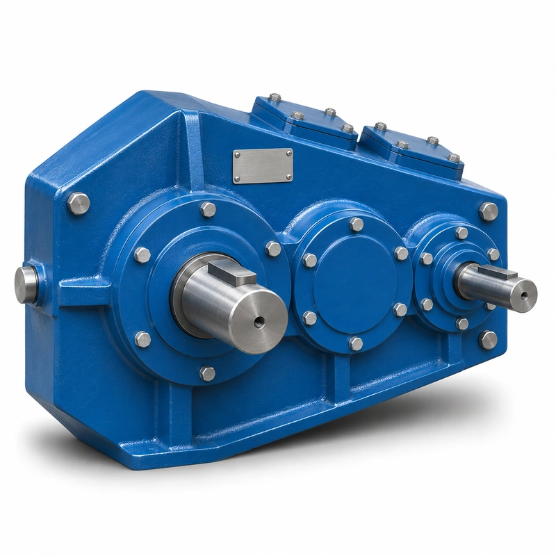
The broader QJR/QJS material contains several mounting and shaft-end variants. It is important to distinguish an ordinary QJR model from QJR-D and to use the correct dimensional drawing when specifying a replacement. QJR and QJS do not have the same ratio range and should not share a product description as though the names were synonyms. The EP-QJR product page focuses on the lower-ratio selection and its associated shaft and bearing interfaces.
Mechanical rationale and transmission selection
Ratio ladder
The QJR series uses six nominal ratio steps. When the mechanism speed falls between steps, verify whether the motor and control system can accommodate the output variation. Do not select the next lower ratio solely because the motor has reserve power; the shaft and driven components may then operate outside their intended speed range.
Input speed dependence
The permissible input power schedule is associated with the selected ratio, nominal centre distance and high-speed shaft rpm. A power value at 570 rpm should not be used unchanged at another speed. For an inverter-controlled crane, document both normal operating speed and the highest sustained speed used under load.
Bearings and overhung loads
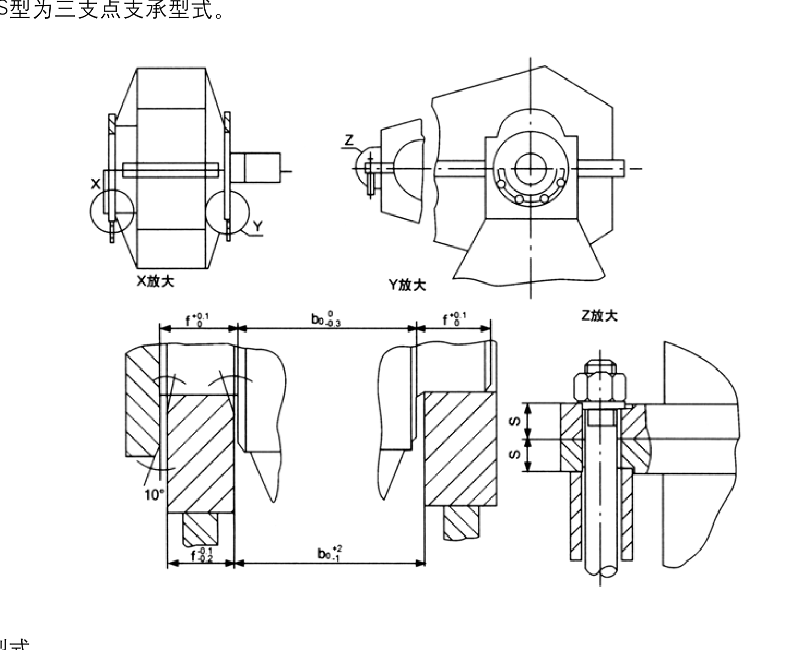
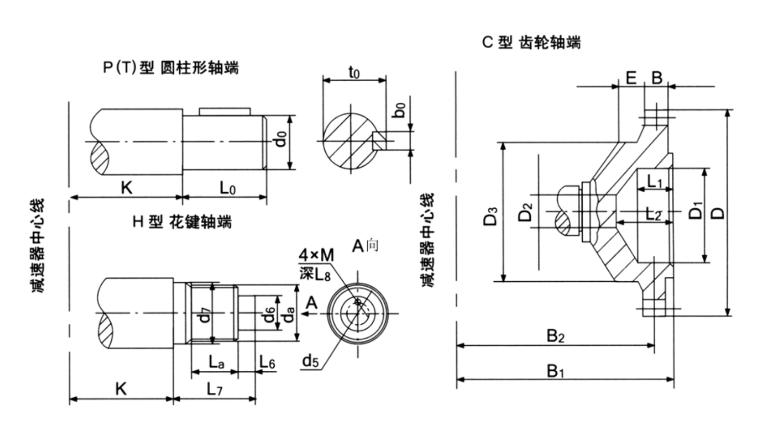
The shared shaft-end diagrams provide interface guidance, but they do not by themselves authorize a radial load at arbitrary distance. When a pulley, gear or sprocket is mounted on the output, include the operating force, location and drive direction. Bearings and housing support must be checked for the applied load case.

Drive stiffness and backlash
Repeated reversing can make drivetrain compliance noticeable. Inspect connected shaft couplings and mechanical clearance before assuming all movement originates in the gearbox. If the project imposes an acceleration or positioning requirement, state it explicitly so the selected arrangement can be evaluated as a system.
Gearbox condition assessment
For a maintenance substitution, take note of oil discoloration, metallic debris, unusual backlash and wear patterns in the retired unit. Those findings can indicate misalignment or overload in the crane mechanism. Replacing the gearbox without understanding the root load issue may lead to the same service problem.
Mounting versions
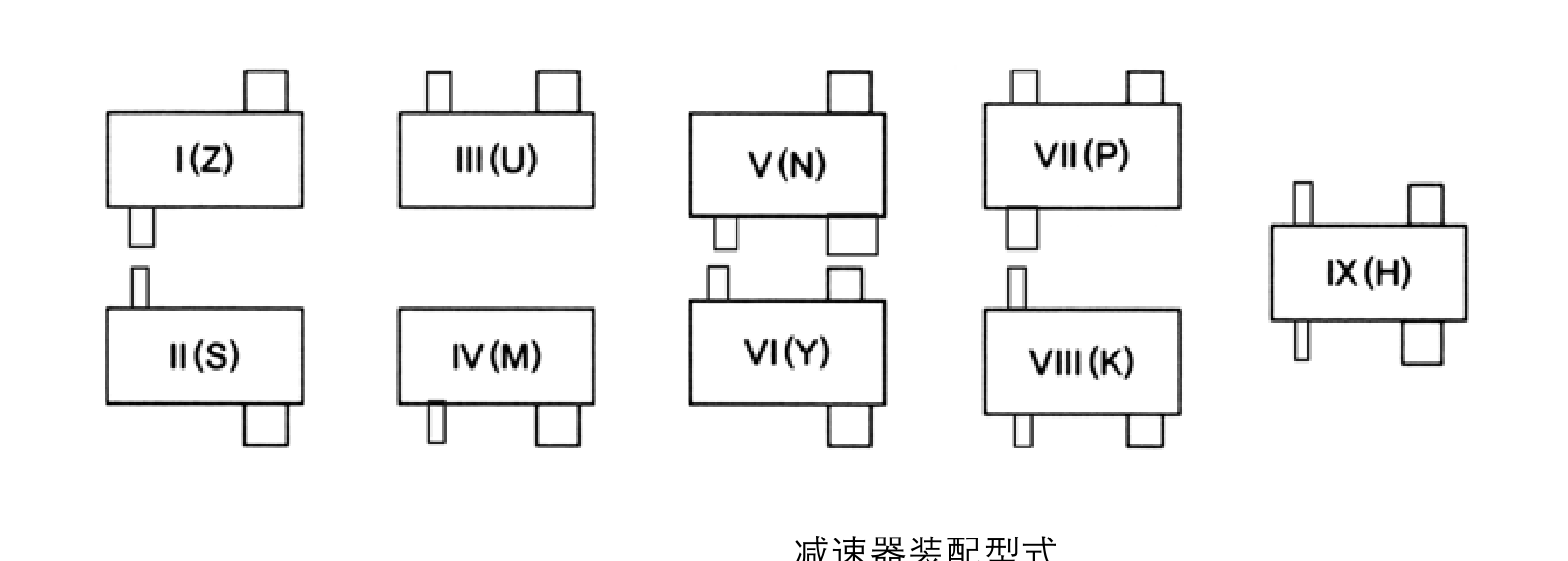
Review P, C or H type mounting and shaft-end layouts where relevant to the project. Two housings may look similar but place a support foot or coupling in a different location. Match the selected arrangement to its dimension view before preparing a foundation or purchase order.

Quote preparation
Provide the requested nominal ratio, exact input rpm, nominal centre distance, output load torque, shaft-end configuration, operating hours and duty class. If the machine is already installed, a measured assembly sketch will often be more useful than a distant photograph of the gear unit.
Speed and rating selection for operating duty
For an EP-QJR installation, the main decision concerns lower-ratio medium-hardened reducer, torque and input speed. Input rpm changes the permissible power schedule and can be decisive for a crane drive with variable frequency. The best starting point is the actual machine arrangement, the operating load and the requested output speed.
Select
Confirm the true mechanical work point for QJR Crane Gear Reducer: input speed, demanded output torque and the dynamic events that govern component loading.
Measure
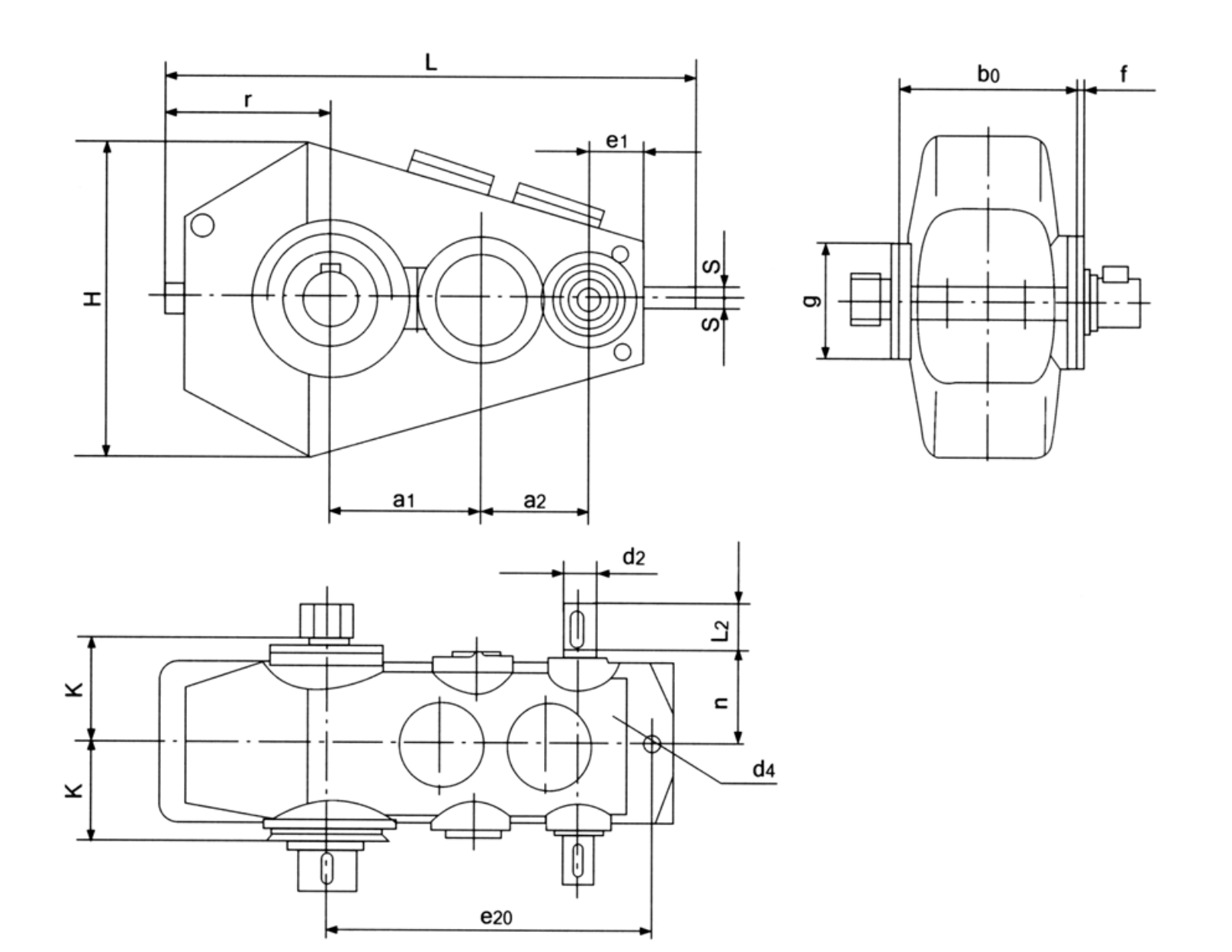
Use the QJR dimensional drawing to validate the installation envelope, shaft interfaces, mounting features and clearances on the actual machine.
Integrate
Match the selected drive with the connected motor, brake, coupling and supporting crane structure. Treat fit and control as one application.
Maintain
Plan access for lubrication, seals, inspection and removal. A compatible gearbox should also be practical to service after the crane is installed.
Motor speed change during modernization
A new VFD or replacement motor can shift the high-speed shaft rpm. Check the allowable power at that speed instead of reusing a QJR rating from a different input-speed column. The target output motion must remain within the machine duty.
Lower-reduction crane duty examples
- Crane mechanisms with moderate reduction ratios: describe the working load and mechanical interface before defining the reducer or gearmotor variant.
- Material-transfer machinery operating at faster output speeds: describe the working load and mechanical interface before defining the reducer or gearmotor variant.
- Industrial MRO replacements using QJR identification: describe the working load and mechanical interface before defining the reducer or gearmotor variant.
QJR specification and model identification
QJR Crane Gear Reducer selection is defined by the combination of family construction, operating point and machine interfaces. The following data identifies the documented product family; a specific configuration must still be checked against its dimensional drawing and duty schedule.


| Parameter | Series-level reference |
|---|---|
| Gear family | QJR medium-hardened crane gear reducers |
| Nominal ratio options | 10, 12.5, 16, 20, 25, 31.5 |
| Nominal centre distances | 140–1000 mm in dimensional family |
| Output torque reference | Must be matched to size and duty; power tables vary by input speed |
| Mount/shaft options | Verify selected bearing and shaft-end drawing |
The nominal centre-distance schedule below covers 15 named frame entries. It is a series index, not a statement that every combination of nominal ratio, shaft end and mounting exists at every size.
| Frame reference | Nominal centre distance | Ordering condition |
|---|---|---|
| Nominal centre a1 = 140 mm | 140 mm | Confirm ratio, interface and load rating for the requested version |
| Nominal centre a1 = 170 mm | 170 mm | Confirm ratio, interface and load rating for the requested version |
| Nominal centre a1 = 200 mm | 200 mm | Confirm ratio, interface and load rating for the requested version |
| Nominal centre a1 = 236 mm | 236 mm | Confirm ratio, interface and load rating for the requested version |
| Nominal centre a1 = 280 mm | 280 mm | Confirm ratio, interface and load rating for the requested version |
| Nominal centre a1 = 335 mm | 335 mm | Confirm ratio, interface and load rating for the requested version |
| Nominal centre a1 = 400 mm | 400 mm | Confirm ratio, interface and load rating for the requested version |
| Nominal centre a1 = 450 mm | 450 mm | Confirm ratio, interface and load rating for the requested version |
| Nominal centre a1 = 500 mm | 500 mm | Confirm ratio, interface and load rating for the requested version |
| Nominal centre a1 = 560 mm | 560 mm | Confirm ratio, interface and load rating for the requested version |
| Nominal centre a1 = 630 mm | 630 mm | Confirm ratio, interface and load rating for the requested version |
| Nominal centre a1 = 710 mm | 710 mm | Confirm ratio, interface and load rating for the requested version |
| Nominal centre a1 = 800 mm | 800 mm | Confirm ratio, interface and load rating for the requested version |
| Nominal centre a1 = 900 mm | 900 mm | Confirm ratio, interface and load rating for the requested version |
| Nominal centre a1 = 1000 mm | 1000 mm | Confirm ratio, interface and load rating for the requested version |
Operating-speed and load references
- One of six listed qjr ratios: include the appropriate drawing, measured value, operating cycle or connection detail.
- High-speed shaft input rpm: include the appropriate drawing, measured value, operating cycle or connection detail.
- Required nominal centre distance: include the appropriate drawing, measured value, operating cycle or connection detail.
- Operating output torque: include the appropriate drawing, measured value, operating cycle or connection detail.
- Bearing load from connected sprocket or coupling: include the appropriate drawing, measured value, operating cycle or connection detail.
- Mounting variant drawing: include the appropriate drawing, measured value, operating cycle or connection detail.
- Rated load frequency: include the appropriate drawing, measured value, operating cycle or connection detail.
- Rotation reversals and annual usage: include the appropriate drawing, measured value, operating cycle or connection detail.
Commercial enquiry for the QJR series
Ever Power can discuss model identification, interface drawings and practical order quantities for the QJR Crane Gear Reducer. Confirmed product configuration, lead time and delivery terms belong in the quotation. Trial and mixed-model requests can be assessed against the total order value.
To compare related drive families, explore the industrial drive product range. The company overview explains the supplier context for engineering and procurement enquiries.
Frequently asked questions about EP-QJR
Which nominal ratios are listed for EP-QJR?
The QJR range is identified with nominal ratios 10, 12.5, 16, 20, 25 and 31.5. Exact available size and rating must be confirmed for the ordered configuration.
Does QJR use the same ratio schedule as QJS?
No. QJR is the lower-ratio range, while QJS and related high-reduction variants are listed at 40–200. Select the correct family before comparing dimensions.
How do I assess an overhung sprocket load?
Provide chain force, sprocket pitch radius, shaft-to-support distance and loading direction, plus the ratio and output speed. A nominal output torque alone is insufficient to approve bearing loading.
Is the purchase quantity fixed for this model for EP-QJR?
There is no blanket unit count for all configurations: MOQ follows the part type and order value. Trials of 1–5 pieces are possible where practical, while a 1–2-piece small order normally has a higher unit price. Mixed-model orders can be considered from about USD 1,500 in aggregate value. For this product, quote preparation should also address lower-ratio medium-hardened reducer, torque and input speed and the requested quantity.
Are quotation delivery dates and trade terms fixed across all sizes for EP-QJR?
No. The standard range is generally 10–25 working days, custom component work 20–45 and project machinery 45–120, subject to actual capacity and engineering scope. Quote-specific terms may use EXW, FOB, CIF or DAP, while FCA, CFR, CPT, CIP and DDP remain options for specific arrangements. Schedule confirmation follows review of the QJR interface and duty requirements.
Find the appropriate QJR ratio and shaft arrangement
Bring your machine data and old reducer drawing to an EP-QJR discussion. A clear ratio and bearing-load specification makes the quotation and installation review more useful.