


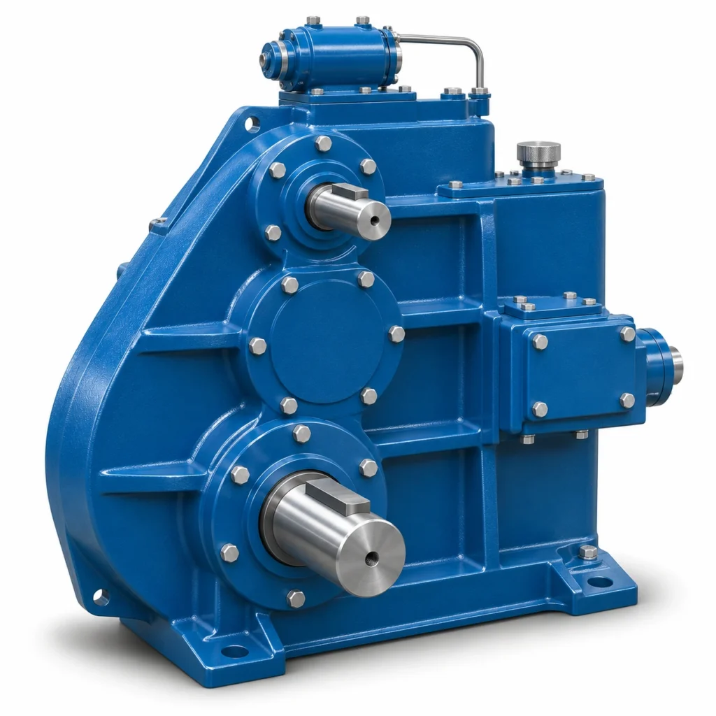
EP-J38GA850 Open-Gear Reducer Assembly is identified as an A850-type horizontal cylindrical gear reducer with an open-gear connection. It has its own external dimensions and assembly sketches, distinct from the larger A1000 reference. The practical purchasing question is whether the installed machine has enough room for the A850 housing and whether the output-side gearing can be positioned correctly within the existing drive. An identical list of nominal ratios on another reducer does not establish equal torque capacity, identical gear tooth interfaces or interchangeable mounting hardware.

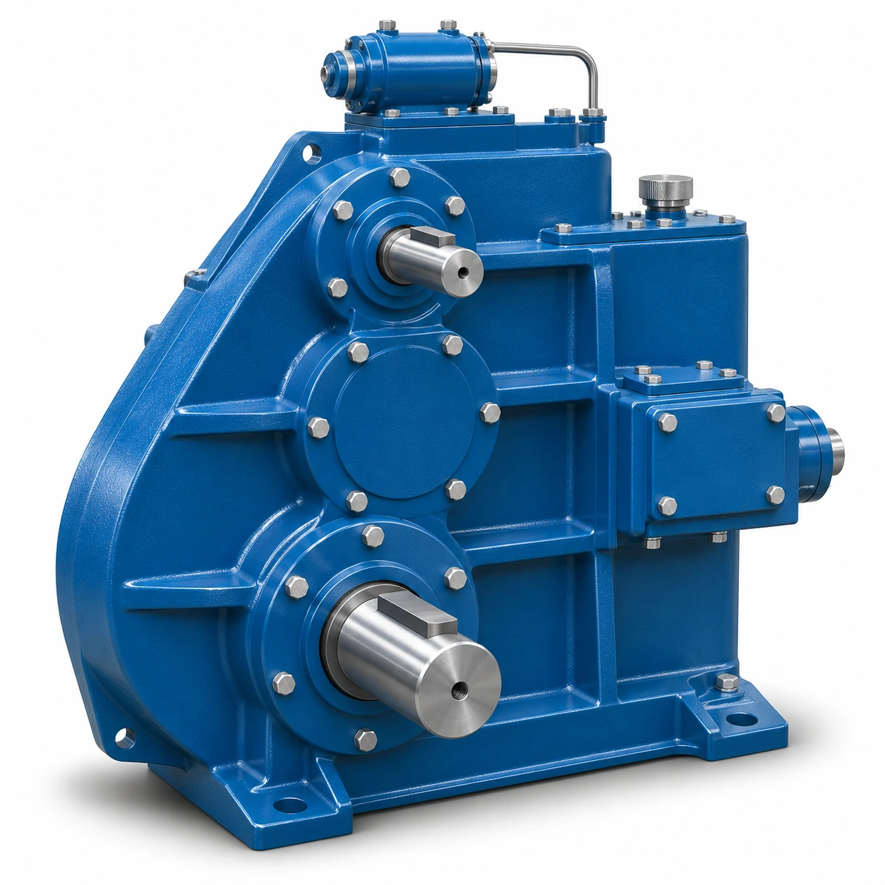
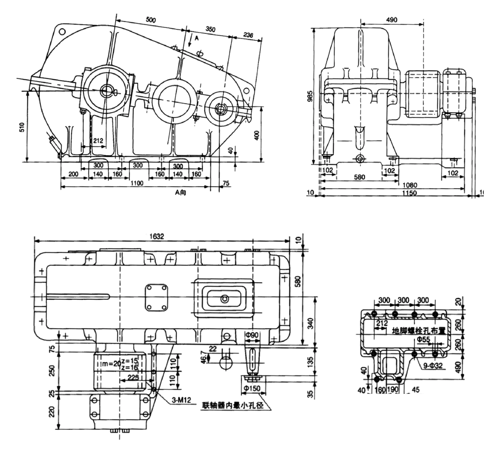
The dimensional views identify a distinct A850 housing with a 1632 mm labeled body reference.
Roman-numeral ratio codes I-IX are used with the A850 selection designation.
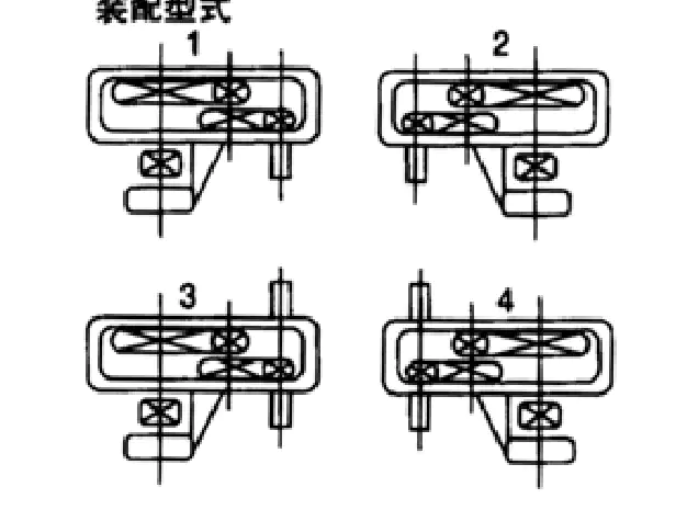
Mounting positions 1-4 change how the reducer connects to the adjacent open-gear equipment.
Identify the A850-Type Reducer Assembly
The A850 reference contains a long main housing, visible shaft-end positions and a side connecting region associated with open-gear transmission. In the view showing the gear centers, the casing follows a shaped rather than a simple rectangular outline. The adjacent arrangement drawing contains two orthogonal views and a separate mounting-position group. Read them together to determine where the connected component will occupy space and where tools will need to reach the fasteners. A product that resembles a J174GA unit at a glance can still differ substantially in its external geometry.
The gearbox should be treated as one part of an installed mechanical system. When a replacement is being ordered, the best starting point is the exact A850 code, the old motor and open-gear connection details, and a verified record of actual shaft positions. If the original drive has been rebuilt several times, the present dimensions on the machine can differ from the original drawing; state such discrepancies explicitly so that they can be evaluated before manufacturing.
J38GA850 Gear Ratio Coding and Reduction Selection
The A850 reference presents ratio codes I through IX. Selecting a code requires more than finding the lowest output rpm: the resulting gearbox output speed has to work with any external pinion or driven gear in the assembly. The motor-to-output rotation direction and the direction in which load torque enters the reducer should also be established, especially for reversing crane movements. Avoid treating the ratio code as a rated motor-power or output-torque value; these are separate engineering parameters.
| Ratio code | I | II | III | IV | V | VI | VII | VIII | IX |
|---|---|---|---|---|---|---|---|---|---|
| Nominal ratio | 48.57 | 40.17 | 31.5 | 23.34 | 20.49 | 15.75 | 12.64 | 10.35 | 8.23 |
The ratio values are reference configuration codes; actual power and torque suitability require confirmation for the selected build.
For applications where the existing motor is retained, measure the actual operating motor speed at the relevant load rather than assuming a nominal synchronous speed. The driven gear train may include an external gear stage; record its tooth count or measured ratio separately. If two reducer candidates have different internal ratios but the same final travel speed, the gear mesh force and bearing reactions can still differ depending on shaft placement and the external gearing arrangement.
A850 Housing Dimensions and Gearbox Footprint
The drawing indicates a 1632 mm main-body length reference, a 985 mm elevation reference and a 1150 mm envelope reference in another projection. They should not be reduced to a generic three-number box size without identifying the actual view and the locations of attached components. The drawing also shows A-direction measurements and a support/mounting arrangement; these are particularly important for ensuring that the reducer locates correctly beside the driven open gear.

| Item | Value | Why it matters |
|---|---|---|
| Product and size notation | J38GA850 / A850 | Use the complete name and model code for ordering |
| Main long-axis reference | 1632 mm | Cross-check the arrow directions and frame space |
| Major height reference | 985 mm | Evaluate installation height and guard clearance |
| Side projection envelope | 1150 mm | Check adjacent motor and connecting gear position |
| Reference assembly weight | 1877 kg | Reconfirm the actual ordered and packed mass |
| Mounting position set | 1, 2, 3, 4 | Define the chosen relative gearbox/gear arrangement |
The above values refer to labeled positions on the reference drawing. Detailed interface dimensions must be read on the drawing itself.
Choosing an A850 Assembly Position
The four mounting sketches are not decorative views of the same installed condition. They show different relative positions between the reducer and the connected mechanical member, affecting how the assembly is built into the crane. When specifying an arrangement, mark the direction of viewing and place the motor or input-shaft location on the same page. If the gear train will be mounted behind an equipment frame, confirm how the reducer can be raised into place and how the connection can be inspected once the machine is closed.

- Identify the chosen assembly position number and the reference viewing side used on the drawing.
- Measure the gear centerline offset and the clearance around the connected component, not only the outside housing.
- Verify that the input and driven shafts are on the required sides and that coupling hubs can be assembled.
- Check fastener access, alignment inspection points and guard clearance before approving installation.
- Confirm that filling, drain and cover points remain reachable after the connected gear is installed.
Open-Gear Meshing and Output Connection Review
An A850 reducer with an associated external gear may carry tooth forces that depend on the pitch geometry and the location of the driven member. A technical quotation should identify whether the output-side gear is included in the requested scope or remains part of the machine. If it remains on the equipment, record the actual tooth geometry and condition. An old gear with uneven flank wear may indicate a support or alignment problem that should be corrected rather than simply replicated in the new housing position.
A useful connection review records the bearing support nearest the gear mesh, the output-shaft projection, tooth or spline engagement where present, and any external retaining elements. The reference illustration cannot independently prove the allowable radial load at a particular distance from the gearbox. Where the driven member imposes a substantial overhung force, obtain the bearing-load capacity and the location at which it is defined for the selected configuration.
A850 versus A1000: What Is and Is Not Comparable
The A850 and A1000 reference products list the same sequence of nominal ratios. That common ratio list is useful when comparing motor and output speed relationships, but the main housing dimensions and assembly mass are different. The A1000 reference is larger and has a separate open-gear interface drawing. The A850 installation should therefore be evaluated on its own rather than treating it as a smaller scale version of an otherwise identical machine. Gear ratio equality does not establish equal gearbox duty, bearing load or mesh compatibility.
| Consideration | J38GA850 / A850 | J174GA-1000 / A1000 |
|---|---|---|
| Ratio code series | I through IX | I through IX |
| Major length callout | 1632 mm | 1896 mm |
| Reference mass | 1877 kg | 2888 kg |
| Drawing and housing | A850-specific, shaped side profile | A1000-specific, separate larger layout |
| Open-gear mating dimensions | Use A850 drawing | Use A1000 drawing |
| Direct interchangeability | Not established | Not established |
The comparison is a dimensional and selection aid only. It does not establish performance equivalence.
Operating Conditions for a J38GA850 Selection
The required operating torque, input speed and daily duty depend on the actual crane or industrial mechanism. Information that is sufficient for a traveling drive may be inadequate for a hoisting mechanism because suspended-load behavior and braking need separate safety consideration. The enquiry should state whether the load is continuous, intermittent, reversing or subject to high impact. Include any external wheel or gear reduction between the gearbox and the driven element, because this changes the ratio and torque seen by the final machine stage.
Confirm motor speed, target reducer output speed and the ratio of the adjacent open-gear pair.
Identify where the meshing force acts and how the shaft and neighboring structure are supported.
State mounting orientation, site temperature, contamination exposure and maintenance access requirements.
Replacement and A850 Inspection Planning
If the old A850 unit is available for measurement, photograph the open-gear connection before disassembly and label the position of the casing relative to a fixed machine datum. Survey bolt and mounting patterns, shaft ends, visible backlash and the condition of the connected member. After removal, the same datum can be used to compare a proposed new drawing. Otherwise, differences in machine position can be mistaken for gearbox dimensional changes.
A broader comparison to the EP-QJR crane gear reducer can help distinguish a conventional enclosed reduction family from an open-gear integrated assembly. The crane gearbox selection range also summarizes other mounting formats. Those existing pages are useful for exploration, but their product photographs and specifications should never be substituted for the A850 reference when compiling the actual purchase order.
Ordering A850 Reducer Assemblies for Crane Projects
The quotation scope should separate the enclosed reducer, attached gear elements and any optional connection or mounting parts. For a heavy assembly, transport and packing conditions should be discussed early, although the reference mass is not a substitute for shipping weight. The buyer should confirm which components will remain on the machine and which are to be newly supplied. This prevents a price comparison between a bare gearbox and a complete connected drive from being misread as a difference in unit price.
- Provide the A850 model marking, ratio code, assembly position and proposed quantity.
- Add drawings or accurate measurements of the open gear, shaft ends, coupling and retention method.
- Identify the foundation datum and available vertical and lateral clearance in the machine.
- State motor data, output target, load cycle, braking scheme and any known wear problem.
- Define whether approval drawings, dimensional inspection records and shipping documents are needed.
Frequently Asked Questions
The following answers focus on the decisions that typically need to be resolved before an engineer can confirm a suitable crane gearbox configuration.
What does the J38GA850 or A850 designation identify?
Are the J38GA850 and J174GA-1000 reducers interchangeable?
Does the 1877 kg figure include final shipping packaging?
Which A850 measurements are most important before ordering?
Can I discuss a small trial order and delivery terms?
Confirm the A850 Assembly Before Ordering
Send your A850 identification, assembly-position sketch, open-gear dimensions, motor and duty information and quantity. Ever Power can discuss an appropriate engineering review and commercial quotation.