


EP-QS Integrated 3-in-1 Crane Gearmotor is specified for integrated motor-reducer package and crane travel selection. QS is a three-in-one crane gearmotor concept rather than a bare speed reducer. It is intended for installations in which the physical relationship between electric motor, reduction gearbox and the driven output must be managed as one package. The frame schedule lists sizes 06, 08, 10, 12, 16, 20 and 25, with nominal centre distance and dimensional data. Because electrical equipment and mechanical output are integrated, an engineer should specify control, voltage, rotation, braking, speed and shaft coupling information together rather than ordering only a gearbox ratio.
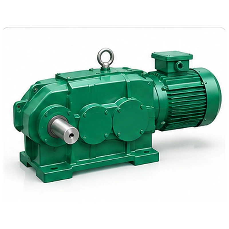
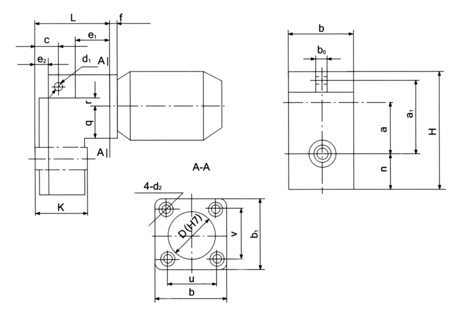
The QS package can simplify a crane mechanism layout, but a compact assembly still needs sufficient access for wiring, servicing, seal inspection and motor removal. The supplied dimension drawing describes the housing and connection features. It does not establish suitability for a particular crane travel wheel or load class. The requested output torque and operating speed must be matched to the selected frame and actual motor arrangement.
Mechanical rationale and transmission selection
Integrated arrangement
Treat the mechanical and electrical sides as one selection. A physically compatible gearhead can still be unusable if motor speed, supply frequency, voltage, enclosure or control approach differs from the machine specification. Include the connected brake arrangement and verify whether the brake is part of the proposed assembly or is mounted elsewhere.

Frame selection
Seven frame designations cover a wide physical range. The frame code affects envelope, weight, shaft interface and available output requirements. Use the exact dimensional row when designing mounting steelwork, especially where a travel trolley has limited clearance to the wheel, frame or limit switches.
Travel duty and reversals
Travel gearmotors often accelerate, decelerate and reverse repeatedly. State the moving load, wheel diameter, target speed, wheel/rail condition, acceleration time, working hours and starts per hour. These variables determine output torque and possible thermal limitations more reliably than a nominal load label on a crane.
Mounting and electrical access
Review the orientation of the terminal box, cable entry, available fan clearance and proximity to moving structures. On outdoor gantry equipment, environmental protection and cable routing should be discussed before configuration approval. A gearmotor with the correct mounting holes can still be unsuitable if maintenance access is blocked.
Output spline geometry
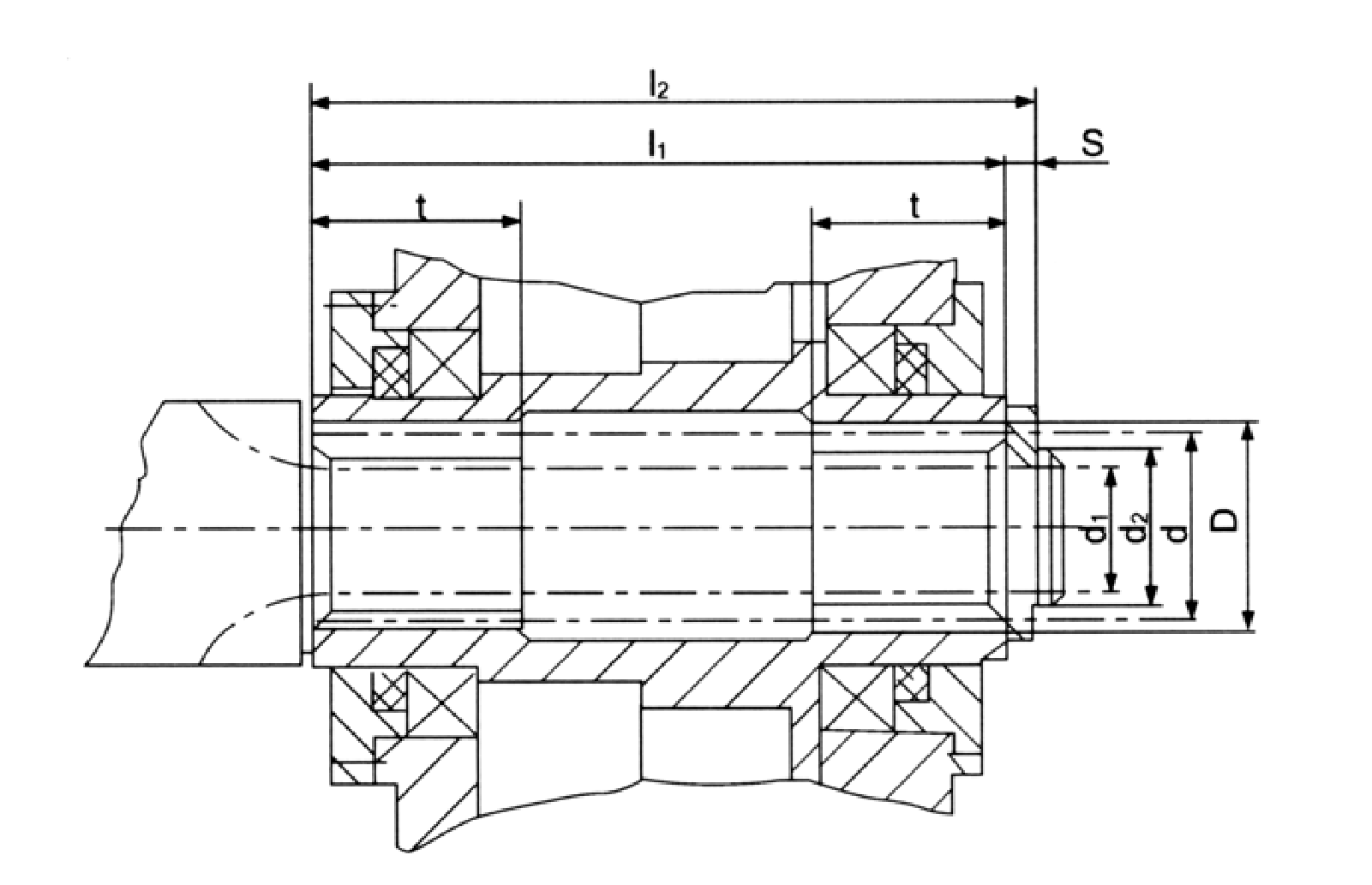
The product data includes internal/external spline references and shaft-end dimensions. A spline designation is only part of the connection specification: verify engaged length, seating, mating shaft form, fit and retention. Never assume a mating component is compatible because its nominal outside diameter appears close.

Motor and brake coordination
If the crane uses a variable-frequency drive, specify motor characteristics, low-speed duty, brake release timing and any controlled stopping requirements. A brake holding a stationary load should not be equated with the motor dynamic torque. The controller and protective devices need coordination with the actual supplied drive.
Service planning
Consider how a motor, brake or gearhead component could be removed without disturbing wheel alignment. Keep the original wiring details and record the installed gearmotor identity so future replacement can match both mechanical and electrical parameters. Check lubricant and seal service against the actual operating orientation.
Electrical and mechanical review for a crane gearmotor
For an EP-QS installation, the main decision concerns integrated motor-reducer package and crane travel selection. Electrical, braking and spline details are inseparable from a usable crane travel gearmotor selection. The best starting point is the actual machine arrangement, the operating load and the requested output speed.
Select
Confirm the true mechanical work point for QS Crane Gearmotor: input speed, demanded output torque and the dynamic events that govern component loading.
Measure
Use the QS dimensional drawing to validate the installation envelope, shaft interfaces, mounting features and clearances on the actual machine.
Integrate
Match the selected drive with the connected motor, brake, coupling and supporting crane structure. Treat fit and control as one application.
Maintain
Plan access for lubrication, seals, inspection and removal. A compatible gearbox should also be practical to service after the crane is installed.
Building a crane trolley drive package
Choose a QS frame using movement resistance, acceleration, spline fit and motor controls together. A compact motor/reducer assembly must clear the trolley structure and provide access to electrical terminals and brake service.
Integrated travel-drive environments
- Bridge and gantry crane travel movements: describe the working load and mechanical interface before defining the reducer or gearmotor variant.
- Compact wheel-drive modules in material handling: describe the working load and mechanical interface before defining the reducer or gearmotor variant.
- New equipment with a coordinated motor-gearbox package: describe the working load and mechanical interface before defining the reducer or gearmotor variant.
QS specification and model identification
QS Crane Gearmotor selection is defined by the combination of family construction, operating point and machine interfaces. The following data identifies the documented product family; a specific configuration must still be checked against its dimensional drawing and duty schedule.
| Parameter | Series-level reference |
|---|---|
| Construction | Integrated motor and reducer assembly; motor/braking details depend on selection |
| Frame codes | 06, 08, 10, 12, 16, 20, 25 |
| Nominal centre-distance values | 125–500 mm in dimensional schedule |
| Connection | Spline-related output interface listed for frame variants |
| Mass data | 27.1–780 kg across listed frames |
QS frame summary
| QS frame | Nominal centre a (mm) | Overall H (mm) | Approx. mass (kg) |
|---|---|---|---|
| QS06 | 125 | 285 | 27.1 |
| QS08 | 160 | 358 | 42.6 |
| QS10 | 200 | 452 | 72.8 |
| QS12 | 250 | 566 | 143.3 |
| QS16 | 315 | 705 | 210 |
| QS20 | 400 | 820 | 320 |
| QS25 | 500 | 1050 | 780 |
Integrated gearmotor electrical and mechanical input
- Travel wheel diameter and rail condition: include the appropriate drawing, measured value, operating cycle or connection detail.
- Moving load and desired speed: include the appropriate drawing, measured value, operating cycle or connection detail.
- Acceleration time and start frequency: include the appropriate drawing, measured value, operating cycle or connection detail.
- Motor voltage/frequency and control: include the appropriate drawing, measured value, operating cycle or connection detail.
- Brake specifications if required: include the appropriate drawing, measured value, operating cycle or connection detail.
- Qs size and spline connection: include the appropriate drawing, measured value, operating cycle or connection detail.
- Cable/terminal orientation: include the appropriate drawing, measured value, operating cycle or connection detail.
- Mount envelope and order quantity: include the appropriate drawing, measured value, operating cycle or connection detail.
Commercial enquiry for the QS series
Ever Power can discuss model identification, interface drawings and practical order quantities for the QS Crane Gearmotor. Confirmed product configuration, lead time and delivery terms belong in the quotation. Trial and mixed-model requests can be assessed against the total order value.
To compare related drive families, explore the industrial drive product range. The company overview explains the supplier context for engineering and procurement enquiries.
Frequently asked questions about EP-QS
What is included in a QS 3-in-1 assembly?
The QS design is an integrated motor-reducer family. The exact motor, brake, mounting adapter and accessories depend on the quotation; request a bill of supply for the specific frame and electrical specification.
How are output splines checked?
Compare the complete spline standard and tooth count, module, mating diameter, fit, engaged length and retention arrangement with the machine shaft. The dimensional drawing should control the final interface.
Can a QS frame be selected using crane tonnage alone?
No. Travel speed, wheel diameter, rail resistance, acceleration, load distribution and duty cycle determine torque. Motor supply and control requirements also affect the suitable drive package.
Is the purchase quantity fixed for this model for EP-QS?
There is no blanket unit count for all configurations: MOQ follows the part type and order value. Trials of 1–5 pieces are possible where practical, while a 1–2-piece small order normally has a higher unit price. Mixed-model orders can be considered from about USD 1,500 in aggregate value. For this product, quote preparation should also address integrated motor-reducer package and crane travel selection and the requested quantity.
When could an engineered crane reducer be delivered for EP-QS?
The schedule depends on the confirmed drawing and production route: standard products typically require 10–25 working days, custom components 20–45 and project-scale equipment 45–120. These are planning ranges, not a promised ship date. Normal trade terms include EXW, FOB, CIF and DAP, with FCA, CFR, CPT, CIP and DDP subject to agreement. Schedule confirmation follows review of the QS interface and duty requirements.
Coordinate the motor and reducer as one crane drive
Share your wheel-drive duty and motor-control specification for an EP-QS gearmotor selection. We can review the required frame, spline connection and operating arrangement.