


EP-QJYA3 Hollow-Shaft Three-Stage Hardened Crane Gearbox is specified for hollow-bore engagement and machine-shaft retention. The EP-QJYA3 is best understood through its output connection. Instead of placing a conventional solid gearbox shaft into a coupling, the gearbox interfaces with a shaft supplied as part of the machine. This arrangement can simplify a drivetrain, but only if the bore, shaft shoulder, engagement length, key or spline form, retention components and torque reaction are all compatible. A nominal hollow-bore diameter without a tolerance callout is not a sufficient order specification. The connection must be defined by a drawing that shows both mating parts.
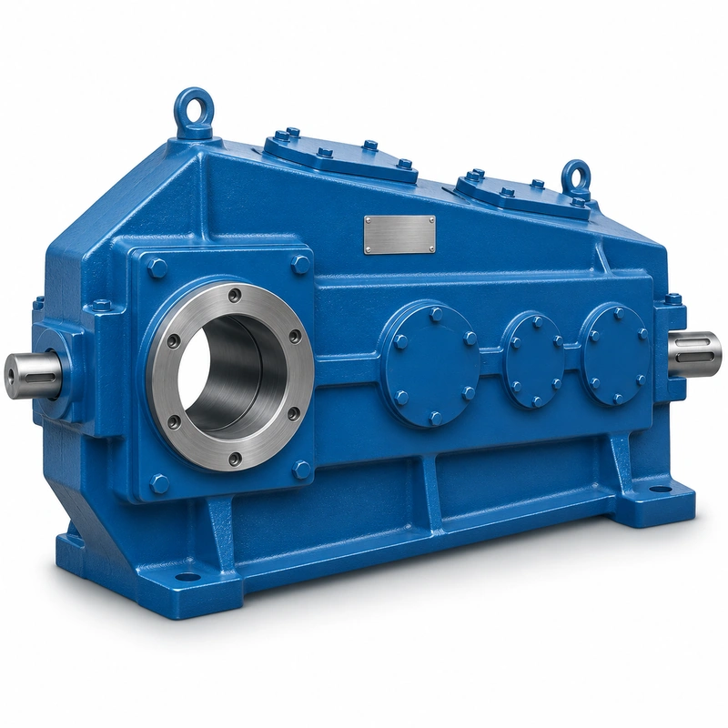
The QJYA family offers several stage configurations, so the QJYA3 name should remain attached to its three-stage model identity. Other QJYA codes in a common shaft connection schedule do not mean all bore sizes are transferable. Before approving a replacement, confirm the work shaft dimensions, any retaining end plate, available insertion depth, and service access for removal. These details affect whether a gearbox can be installed safely without modifying the load-bearing shaft.
Mounting and operating behavior of EP-QJYA3

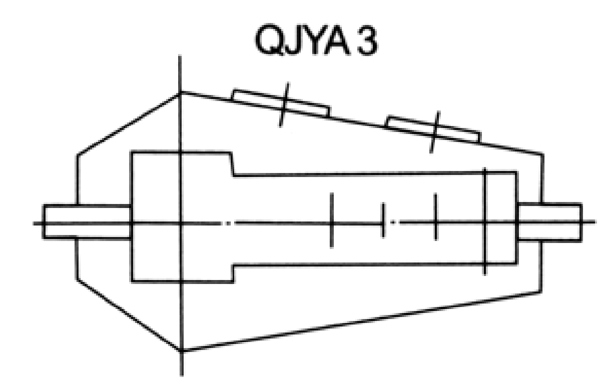
Bore and shaft fit
Identify the bore nominal size, specified fit, actual shaft measurement and any keyway profile. Check whether the existing shaft is worn at the gearbox seat or has fretting at the transmission interface. Retaining a worn shaft may compromise a new reducer even when the nominal dimensions match. A shaft sketch should show tolerances, chamfers and surface condition.

External torque reaction
A hollow-shaft gearbox may still require a torque arm or other support arrangement. Determine where casing reaction goes, its direction under forward/reverse operation and any permitted articulation. Fastening the housing rigidly at an unintended point can load bearings and distort the case.
Axial retention and service
The installation should positively define how the gearbox is restrained axially, and how it can be withdrawn during service. Document end-plate size, fasteners, shoulders and puller access. Do not assume axial forces can be transmitted through the gear train unless an authorized engineering drawing specifies that load path.
QJYA3 specification and model identification
QJYA3 Hollow Shaft Crane Gearbox selection is defined by the combination of family construction, operating point and machine interfaces. The following data identifies the documented product family; a specific configuration must still be checked against its dimensional drawing and duty schedule.
| Parameter | Series-level reference |
|---|---|
| Output connection | Hollow shaft; mating machine shaft fit is critical |
| Gear stages | 3 |
| Nominal ratio | 20–100 for three-stage QJY family |
| Nominal centre-distance range | 170–800 mm family; special larger interfaces require review |
| Shaft data | Hollow bore, mating shaft and end-plate features in QJYA series schedule |
The nominal centre-distance schedule below covers 13 named frame entries. It is a series index, not a statement that every combination of nominal ratio, shaft end and mounting exists at every size.
| Frame reference | Nominal centre distance | Ordering condition |
|---|---|---|
| Nominal centre a1 = 170 mm | 170 mm | Confirm ratio, interface and load rating for the requested version |
| Nominal centre a1 = 200 mm | 200 mm | Confirm ratio, interface and load rating for the requested version |
| Nominal centre a1 = 236 mm | 236 mm | Confirm ratio, interface and load rating for the requested version |
| Nominal centre a1 = 280 mm | 280 mm | Confirm ratio, interface and load rating for the requested version |
| Nominal centre a1 = 335 mm | 335 mm | Confirm ratio, interface and load rating for the requested version |
| Nominal centre a1 = 370 mm | 370 mm | Confirm ratio, interface and load rating for the requested version |
| Nominal centre a1 = 400 mm | 400 mm | Confirm ratio, interface and load rating for the requested version |
| Nominal centre a1 = 450 mm | 450 mm | Confirm ratio, interface and load rating for the requested version |
| Nominal centre a1 = 500 mm | 500 mm | Confirm ratio, interface and load rating for the requested version |
| Nominal centre a1 = 560 mm | 560 mm | Confirm ratio, interface and load rating for the requested version |
| Nominal centre a1 = 630 mm | 630 mm | Confirm ratio, interface and load rating for the requested version |
| Nominal centre a1 = 710 mm | 710 mm | Confirm ratio, interface and load rating for the requested version |
| Nominal centre a1 = 800 mm | 800 mm | Confirm ratio, interface and load rating for the requested version |
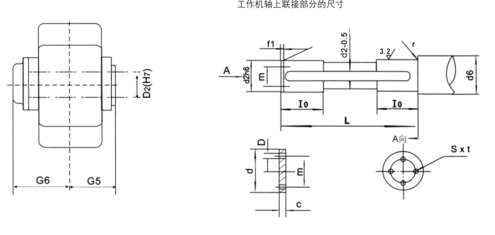
Hollow-shaft and mating-shaft dimension rows
| Nominal size | D2 (mm) | G5 (mm) | G6 (mm) | d2 (mm) | d6 (mm) | f1 | L (mm) | l0 (mm) | r | s | t | C | D | d | m |
|---|---|---|---|---|---|---|---|---|---|---|---|---|---|---|---|
| 170 | 90 | 155 | 195 | 90 | 100 | 4 | 308 | 40 | 2.5 | 10 | 17 | 10 | 11 | 100 | 60 |
| 200 | 100 | 167 | 207 | 100 | 110 | 5 | 332 | 50 | 4 | 10 | 17 | 10 | 11 | 120 | 70 |
| 236 | 120 | 190 | 232 | 120 | 130 | 5 | 378 | 50 | 4 | 12 | 20 | 12 | 14 | 140 | 80 |
| 280 | 140 | 215 | 257 | 140 | 150 | 5 | 428 | 65 | 4 | 12 | 20 | 12 | 14 | 160 | 90 |
| 335 | 160 | 245 | 298 | 160 | 170 | 6 | 488 | 65 | 4 | 12 | 20 | 23 | 14 | 160 | 90 |
| 370 | 180 | 275 | 328 | 180 | 190 | 6 | 548 | 75 | 4 | 12 | 20 | 23 | 14 | 200 | 90 |
Torque transmission path
Understand how torque passes through the key, spline or frictional connection and how that path is supported along the engagement length. A large bore does not prove adequate torque capacity. The machine shaft, retaining plate and gearbox coupling interface must be considered as one system under starting and reversing loads.
Bore table interpretation
The shaft-connection schedule includes standard entries for selected smaller frames and marks larger sizes for special design. It must not be extrapolated to a larger custom bore. Use the provided shaft-end diagram as the controlling interface for each proposed build, and request a revised drawing for special orders.
Dismantling and inspection
Before removing an old hollow-shaft reducer, check retention hardware and support the gearbox weight so it cannot bind on the shaft. Photograph the shaft seat after removal, measure actual diameters and inspect keys or splines. The new assembly should be tested for fit before commissioning at operating load.
Transmission speed and load
A nominal ratio from the 20–100 three-stage family helps estimate operating speed, but detailed shaft torque and drive conditions still determine suitability. Supply the full load cycle, input speed, expected shock and reversal count. This is especially important where the machine shaft cannot readily be replaced if the connection is overstressed.
Shaft-interface selection considerations
For an EP-QJYA3 installation, the main decision concerns hollow-bore engagement and machine-shaft retention. The work shaft is effectively one half of the transmission connection; it should be represented in the drawing. The best starting point is the actual machine arrangement, the operating load and the requested output speed.
Select
Confirm the true mechanical work point for QJYA3 Hollow Shaft Crane Gearbox: input speed, demanded output torque and the dynamic events that govern component loading.
Measure
Use the QJYA3 dimensional drawing to validate the installation envelope, shaft interfaces, mounting features and clearances on the actual machine.
Integrate
Match the selected drive with the connected motor, brake, coupling and supporting crane structure. Treat fit and control as one application.
Maintain
Plan access for lubrication, seals, inspection and removal. A compatible gearbox should also be practical to service after the crane is installed.
Fitting to a retained machine shaft
An existing crane shaft can be reused only if the actual shaft seat and retention details meet the proposed hollow-bore interface. Measure the bearing journal, key or spline, shoulder positions and permissible withdrawal travel.
Where a hollow output makes mechanical sense
- Crane drum or travel shaft with direct hollow-bore engagement: describe the working load and mechanical interface before defining the reducer or gearmotor variant.
- Compact equipment where an external coupling is undesirable: describe the working load and mechanical interface before defining the reducer or gearmotor variant.
- Shaft-mounted replacement projects constrained by support clearances: describe the working load and mechanical interface before defining the reducer or gearmotor variant.
Hollow-bore mating-shaft specification
- Machine shaft actual measured diameter: include the appropriate drawing, measured value, operating cycle or connection detail.
- Bore and key or spline requirement: include the appropriate drawing, measured value, operating cycle or connection detail.
- Mating engagement length and shoulders: include the appropriate drawing, measured value, operating cycle or connection detail.
- Axial retaining end-plate sketch: include the appropriate drawing, measured value, operating cycle or connection detail.
- Torque-reaction restraint: include the appropriate drawing, measured value, operating cycle or connection detail.
- Input motor rpm: include the appropriate drawing, measured value, operating cycle or connection detail.
- Maximum working output torque: include the appropriate drawing, measured value, operating cycle or connection detail.
- Available gearbox withdrawal length: include the appropriate drawing, measured value, operating cycle or connection detail.
Commercial enquiry for the QJYA3 series
Ever Power can discuss model identification, interface drawings and practical order quantities for the QJYA3 Hollow Shaft Crane Gearbox. Confirmed product configuration, lead time and delivery terms belong in the quotation. Trial and mixed-model requests can be assessed against the total order value.
To compare related drive families, explore the industrial drive product range. The company overview explains the supplier context for engineering and procurement enquiries.
Frequently asked questions about EP-QJYA3
What is the single most important dimension for QJYA3?
The full hollow-shaft-to-machine-shaft interface is more important than any single diameter. Include mating fits, engagement length, retaining end-plate geometry, shoulders and any keyway or spline specification.
Are larger QJYA3 bore sizes standard?
Not all listed nominal centre distances have published standard shaft-interface data. The larger interface entries may require special design; confirm each proposed bore and retention system before quoting.
Can QJYA3 use a solid-output QJY3 shaft drawing?
No. A solid-shaft illustration cannot define a hollow-shaft mating surface or the machine-side retention system. The QJYA3 connection drawing must be used.
How does a trial order work for a customized gearbox for EP-QJYA3?
For a suitable trial build, a new customer may request 1–5 samples. A 1–2-piece production order can sometimes be accommodated with a higher per-unit cost. Different gear-unit models may be combined in one commercial order if the overall minimum order value is around USD 1,500. Final MOQ depends on the configuration. For this product, quote preparation should also address hollow-bore engagement and machine-shaft retention and the requested quantity.
What lead time and shipping terms apply after the drawing is approved for EP-QJYA3?
For initial planning, use 10–25 working days for standard configurations, 20–45 for custom components and 45–120 for project units. The binding schedule follows engineering review and order acceptance. EXW/FOB/CIF/DAP are common quotation bases; FCA/CFR/CPT/CIP/DDP can be negotiated on a case-by-case basis. Schedule confirmation follows review of the QJYA3 interface and duty requirements.
Review your hollow-shaft connection
Upload your existing work-shaft drawing and retention details for an EP-QJYA3 quotation. Matching the mechanical interface is the first step toward a reliable crane reducer selection.