


EP-QJS High-Reduction Medium-Hardened Crane Gearbox is specified for high-ratio medium-hardened drive and low-speed shaft control. QJS addresses crane mechanisms where the drive requires a higher nominal reduction than the QJR range provides. The listed QJS ratios extend from 40 to 200 in eight defined steps. This gives the machine designer a way to match a higher-speed motor to slower driven machinery, subject to torque and thermal limits. The ratio choice should reflect the required load motion, not merely the motor power or an existing gearbox casing size.
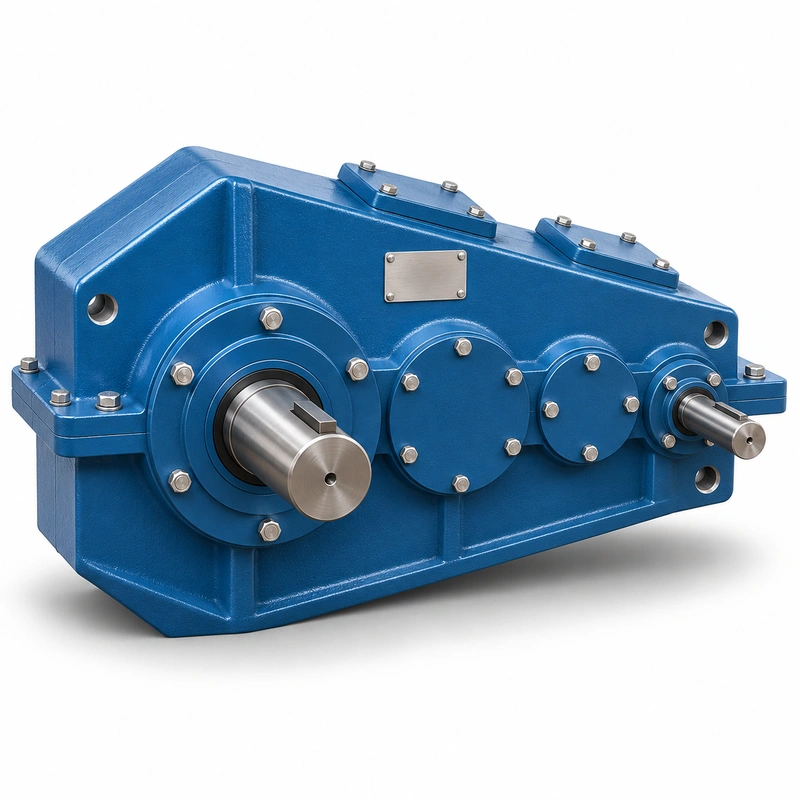
A QJS installation is sensitive to the relationship between output speed, accumulated backlash and external equipment loads. When a crane lift or travel mechanism runs intermittently, the peak torque during start or brake transition can differ from its settled running torque. A high-reduction gearbox is not automatically a holding brake. The brake and drive controls are separate system elements and must be evaluated together with the gear train.
QJS machine-matching framework
A high-reduction drive in its complete crane system
For an EP-QJS installation, the main decision concerns high-ratio medium-hardened drive and low-speed shaft control. High reduction does not mean self-locking or inherently safe load holding. The best starting point is the actual machine arrangement, the operating load and the requested output speed.
Select
Confirm the true mechanical work point for QJS Crane Gearbox: input speed, demanded output torque and the dynamic events that govern component loading.
Measure
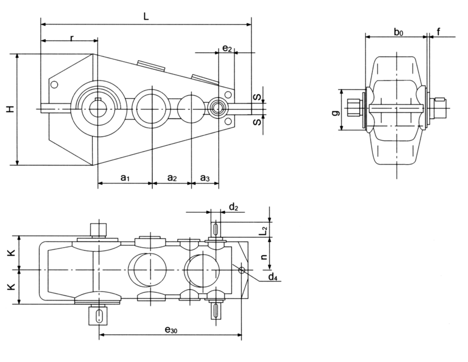
Use the QJS dimensional drawing to validate the installation envelope, shaft interfaces, mounting features and clearances on the actual machine.
Integrate
Match the selected drive with the connected motor, brake, coupling and supporting crane structure. Treat fit and control as one application.
Maintain
Plan access for lubrication, seals, inspection and removal. A compatible gearbox should also be practical to service after the crane is installed.
Very slow controlled crane motion
A higher nominal ratio helps achieve reduced output speed, but the required torque and motor-control behaviour still need verification. Confirm the independent holding brake and the thermal implications of long slow running before selecting a model.
Slower crane motion and load control
- Low-speed crane lifting and handling equipment: describe the working load and mechanical interface before defining the reducer or gearmotor variant.
- Industrial travel drives requiring high reduction ratios: describe the working load and mechanical interface before defining the reducer or gearmotor variant.
- Retrofit of an older QJS/QJRS tagged drive: describe the working load and mechanical interface before defining the reducer or gearmotor variant.
High-reduction gearbox RFQ checklist
QJS specification and model identification
QJS Crane Gearbox selection is defined by the combination of family construction, operating point and machine interfaces. The following data identifies the documented product family; a specific configuration must still be checked against its dimensional drawing and duty schedule.

| Parameter | Series-level reference |
|---|---|
| Product group | QJS / related QJRS high-reduction family |
| Nominal ratio options | 40, 50, 63, 80, 100, 125, 160, 200 |
| Nominal centre distances | 140–1000 mm in dimensional family |
| Use case | Slower mechanical outputs relative to the high-speed input |
| Interface | Mounting and shaft ends checked against selected drawing |
The nominal centre-distance schedule below covers 15 named frame entries. It is a series index, not a statement that every combination of nominal ratio, shaft end and mounting exists at every size.
| Frame reference | Nominal centre distance | Ordering condition |
|---|---|---|
| Nominal centre a1 = 140 mm | 140 mm | Confirm ratio, interface and load rating for the requested version |
| Nominal centre a1 = 170 mm | 170 mm | Confirm ratio, interface and load rating for the requested version |
| Nominal centre a1 = 200 mm | 200 mm | Confirm ratio, interface and load rating for the requested version |
| Nominal centre a1 = 236 mm | 236 mm | Confirm ratio, interface and load rating for the requested version |
| Nominal centre a1 = 280 mm | 280 mm | Confirm ratio, interface and load rating for the requested version |
| Nominal centre a1 = 335 mm | 335 mm | Confirm ratio, interface and load rating for the requested version |
| Nominal centre a1 = 400 mm | 400 mm | Confirm ratio, interface and load rating for the requested version |
| Nominal centre a1 = 450 mm | 450 mm | Confirm ratio, interface and load rating for the requested version |
| Nominal centre a1 = 500 mm | 500 mm | Confirm ratio, interface and load rating for the requested version |
| Nominal centre a1 = 560 mm | 560 mm | Confirm ratio, interface and load rating for the requested version |
| Nominal centre a1 = 630 mm | 630 mm | Confirm ratio, interface and load rating for the requested version |
| Nominal centre a1 = 710 mm | 710 mm | Confirm ratio, interface and load rating for the requested version |
| Nominal centre a1 = 800 mm | 800 mm | Confirm ratio, interface and load rating for the requested version |
| Nominal centre a1 = 900 mm | 900 mm | Confirm ratio, interface and load rating for the requested version |
| Nominal centre a1 = 1000 mm | 1000 mm | Confirm ratio, interface and load rating for the requested version |
Thermal performance
A larger ratio may be achieved with an additional reduction stage or different internal configuration, producing a different loss distribution. Check input speed, operating duty, ambient conditions and lubrication requirements. Slow output motion should not be mistaken for low heat generation inside the gearbox.
Load holding and braking
Confirm how the machine remains stationary when the motor is not energized. A geared reduction can influence reflected inertia and brake sizing but should not be described as a positive lock. Document brake type, actuation time, control sequence and any required load-holding function independently of the nominal gearbox ratio.
Eight-step ratio selection
Work from the target shaft rpm and load torque to the nominated ratio. Ratios 40, 50, 63, 80, 100, 125, 160 and 200 do not imply identical torque rating at one frame size. Use the rated power schedule for the selected ratio and actual high-speed shaft rpm. A low ratio may be inappropriate if it makes the driven machine run too fast under the same motor.
Mounting choices
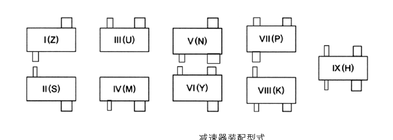
The common product information includes multiple installation forms. Choose the mounting type based on the machine support path and provide the exact construction code. Avoid repurposing a QJR drawing just because the external proportions appear close.

Long-term inspection
Monitor for shifts in noise, bearing temperature and oil contamination under repeatable conditions. In systems with infrequent but severe loading, inspect after actual high-load operating events rather than relying exclusively on calendar intervals. Review the connected support steelwork and couplings because faults elsewhere can be transferred into the gear train.
Mechanical shaft interface
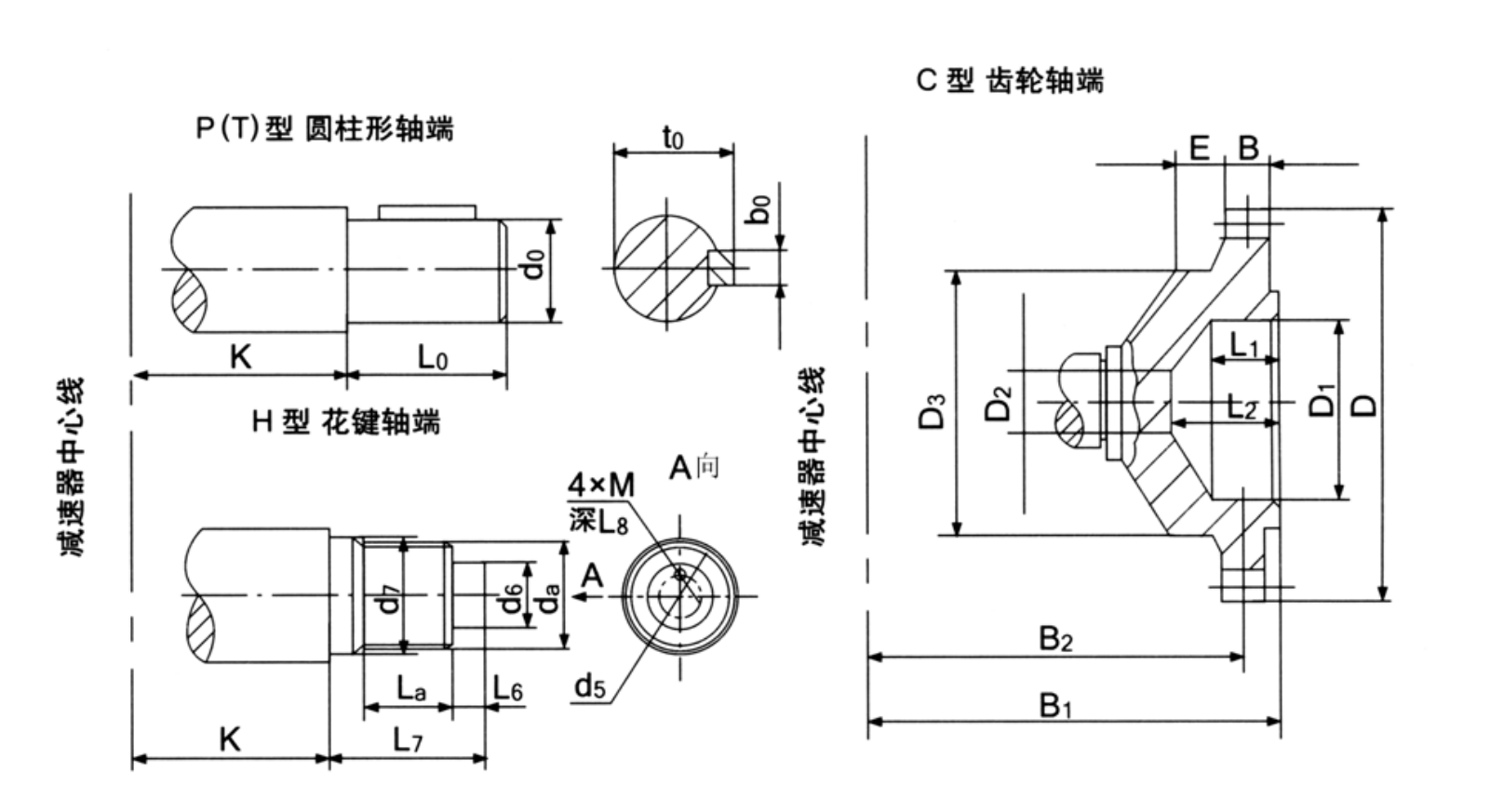
Because QJS can be used in heavy machinery, record coupling diameter, keyway or spline data, shaft extension, output direction and bearing loads. A flange photograph is insufficient to establish the interface. The shaft-end schematic and the actual order drawing should agree with the connected machine.

Crane duty and service factor
Describe average load, frequency of rated lifts, starts per hour and any abrupt reversing. A nameplate ratio does not communicate those operating stresses. Ask for the selected gearbox rating under the intended duty, then check whether the machine requires extra mechanical margin.

- One of eight qjs ratios: include the appropriate drawing, measured value, operating cycle or connection detail.
- Required low-speed output rpm: include the appropriate drawing, measured value, operating cycle or connection detail.
- Existing brake configuration: include the appropriate drawing, measured value, operating cycle or connection detail.
- Load holding requirement: include the appropriate drawing, measured value, operating cycle or connection detail.
- Nominal centre distance and motor speed: include the appropriate drawing, measured value, operating cycle or connection detail.
- Shaft and coupling measurement: include the appropriate drawing, measured value, operating cycle or connection detail.
- Thermal and lubrication environment: include the appropriate drawing, measured value, operating cycle or connection detail.
- Crane classification or duty description: include the appropriate drawing, measured value, operating cycle or connection detail.
Commercial enquiry for the QJS series
Ever Power can discuss model identification, interface drawings and practical order quantities for the QJS Crane Gearbox. Confirmed product configuration, lead time and delivery terms belong in the quotation. Trial and mixed-model requests can be assessed against the total order value.
To compare related drive families, explore the industrial drive product range. The company overview explains the supplier context for engineering and procurement enquiries.
Frequently asked questions about EP-QJS
What nominal ratios belong to QJS?
QJS is associated with nominal ratios 40, 50, 63, 80, 100, 125, 160 and 200. The final combination must be confirmed for the selected nominal centre distance and operating duty.
Does a 200:1 gearbox eliminate the need for a brake?
No. The gearbox provides speed reduction, not a certified load-holding mechanism. Brake and safety-system design must be addressed independently for the crane application.
What is needed to match a QJS replacement?
Send the original ratio, output rpm, motor speed, mounting code, shaft dimensions and machine load cycle. An installation drawing and photo of the existing unit help identify the correct form.
Can a distributor combine several reducer models in a trial shipment for EP-QJS?
Yes, mixed model quantities may be assessed together against an approximate USD 1,500 minimum order value. A new distributor can ask for 1–5 trial pieces when practical. Very small requests of 1–2 units may be accepted, but should be priced as a small production batch rather than standard-volume procurement. For this product, quote preparation should also address high-ratio medium-hardened drive and low-speed shaft control and the requested quantity.
Are quotation delivery dates and trade terms fixed across all sizes for EP-QJS?
No. The standard range is generally 10–25 working days, custom component work 20–45 and project machinery 45–120, subject to actual capacity and engineering scope. Quote-specific terms may use EXW, FOB, CIF or DAP, while FCA, CFR, CPT, CIP and DDP remain options for specific arrangements. Schedule confirmation follows review of the QJS interface and duty requirements.
Plan a controlled high-ratio drive replacement
Describe the hoist or travel mechanism and its required low-speed output. An EP-QJS enquiry can then be checked against the selected ratio, shaft interfaces and operating duty.