


EP-QY3S Three-Support Hardened Crane Gearbox is specified for three-point support integrity and gearbox interface placement. A QY3S crane gearbox is often selected around the position of the supporting points before a shaft coupling is chosen. The casing has to sit in the designated support scheme, while the input and output centerlines meet the adjacent drum, travel gear or shaft train without forcing the coupling to compensate for a poor installation. The nominal centre distance describes a gear-train size; it is not a substitute for a three-dimensional interface drawing. On an existing crane, the attachment geometry may be more limiting than the requested ratio. An EP-QY3S proposal should therefore begin with the old-unit envelope, feet/support locations and any restrictions imposed by the surrounding steelwork.
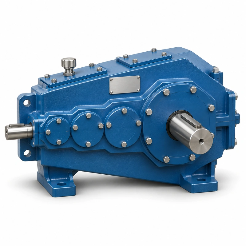
This is a three-stage family, not an arbitrary collection of gearboxes with similar blue housings. Intermediate gearing changes the space occupied by the gear train and the relationship between torque rating and speed. A buyer evaluating a lifting unit should distinguish operating output torque from short-duration events such as starts, reversals or load pickup. Those events affect shaft stresses, gear tooth contact and coupling selection. They also determine how much latitude exists for a replacement gearbox with the same basic reduction. A drawing that merely matches the outside length cannot demonstrate suitable service under the crane duty.
QY3S specification and model identification
QY3S Crane Gearbox selection is defined by the combination of family construction, operating point and machine interfaces. The following data identifies the documented product family; a specific configuration must still be checked against its dimensional drawing and duty schedule.

| Parameter | Series-level reference |
|---|---|
| Series layout | Three-support arrangement; select according to the exact support drawing |
| Stage family | Three-stage QY configuration |
| Nominal ratio selection | 16–90 (verify available ratios by size) |
| Nominal centre distance | 160–800 mm family range |
| Duty | Application-specific output torque and input speed must be checked |
The nominal centre-distance schedule below covers 15 named frame entries. It is a series index, not a statement that every combination of nominal ratio, shaft end and mounting exists at every size.
| Frame reference | Nominal centre distance | Ordering condition |
|---|---|---|
| Nominal centre a1 = 160 mm | 160 mm | Confirm ratio, interface and load rating for the requested version |
| Nominal centre a1 = 180 mm | 180 mm | Confirm ratio, interface and load rating for the requested version |
| Nominal centre a1 = 200 mm | 200 mm | Confirm ratio, interface and load rating for the requested version |
| Nominal centre a1 = 225 mm | 225 mm | Confirm ratio, interface and load rating for the requested version |
| Nominal centre a1 = 250 mm | 250 mm | Confirm ratio, interface and load rating for the requested version |
| Nominal centre a1 = 280 mm | 280 mm | Confirm ratio, interface and load rating for the requested version |
| Nominal centre a1 = 315 mm | 315 mm | Confirm ratio, interface and load rating for the requested version |
| Nominal centre a1 = 355 mm | 355 mm | Confirm ratio, interface and load rating for the requested version |
| Nominal centre a1 = 400 mm | 400 mm | Confirm ratio, interface and load rating for the requested version |
| Nominal centre a1 = 450 mm | 450 mm | Confirm ratio, interface and load rating for the requested version |
| Nominal centre a1 = 500 mm | 500 mm | Confirm ratio, interface and load rating for the requested version |
| Nominal centre a1 = 560 mm | 560 mm | Confirm ratio, interface and load rating for the requested version |
| Nominal centre a1 = 630 mm | 630 mm | Confirm ratio, interface and load rating for the requested version |
| Nominal centre a1 = 710 mm | 710 mm | Confirm ratio, interface and load rating for the requested version |
| Nominal centre a1 = 800 mm | 800 mm | Confirm ratio, interface and load rating for the requested version |
QY3S construction, duty and interfacing
Three-support envelope
For a crane designer, establish which supporting point fixes the gearbox position and which points accommodate assembly tolerances. Check the vertical and lateral offsets from the drum or driven shaft, the clearance below nearby machinery, and the expected torque reaction path. Do not treat the three points as interchangeable with ordinary foot-mount holes. A different housing can fit between structures but still load the support brackets incorrectly. Include photographs of the complete installation, not only a close-up of the nameplate.


Duty cycle and load
Identify the crane mechanism class, number of starts per hour, load spectrum, reversing frequency and actual running hours. Starting torque may materially exceed the steady-state load torque. A gearbox selected only against the motor nameplate can be undersized when a loaded drum accelerates or an inverter commands aggressive speed changes. Conversely, oversizing without checking support dimensions can create unnecessary retrofit work.
Ratio and speed
Use the specified input speed and the required drum or travel output speed to select the nominal reduction. The listed family covers 16–100 as a series-level range; a particular centre distance does not necessarily support every listed nominal ratio. The exact gear-set ratio may differ from the nominal name, so speed verification is essential when matching an existing crane or coordinating several synchronized drives.
Input/output interface
Confirm input-shaft diameter, usable shaft length, keyway form, coupling hub position and output orientation. Record radial loads at the shaft and the distance from the bearing support whenever a sprocket or gear wheel is mounted directly. Check axial forces separately; the presence of a robust output flange does not establish an allowable axial rating.
Replacement identification
Provide the existing unit code, ratio, nominal centre distance, support layout and shaft drawings. Older cranes can contain field modifications that are not visible in a standard drawing. If the plant has changed the motor, coupling, brake or drum since commissioning, include those details because they may change the torque and speed assumptions used by the original gearbox designer.
Installation and alignment
Inspect the condition of the three support seats and any mechanical shims before fitting the unit. Measure the output reference axis in relation to the driven mechanism; avoid using the coupling as an alignment tool. After installation, check unloaded running, vibration, leak paths, bearing temperature and bolt security, then repeat under a controlled representative operating load.
Inspection and maintenance
Confirm the lubricant type and fill arrangement for the final installation orientation. Review seal wear where shaft misalignment may have produced uneven loading. Trend noise and temperature against a repeatable duty point rather than one unloaded test. When checking the casing, pay particular attention to support distortion, loosening at the attachment points and paint cracking around highly stressed mounting features.
Decision points for crane equipment integration
For an EP-QY3S installation, the main decision concerns three-point support integrity and gearbox interface placement. The design review should resolve the three mechanical supports before it resolves paint colour or cosmetic enclosure differences. The best starting point is the actual machine arrangement, the operating load and the requested output speed.
Select
Confirm the true mechanical work point for QY3S Crane Gearbox: input speed, demanded output torque and the dynamic events that govern component loading.
Measure
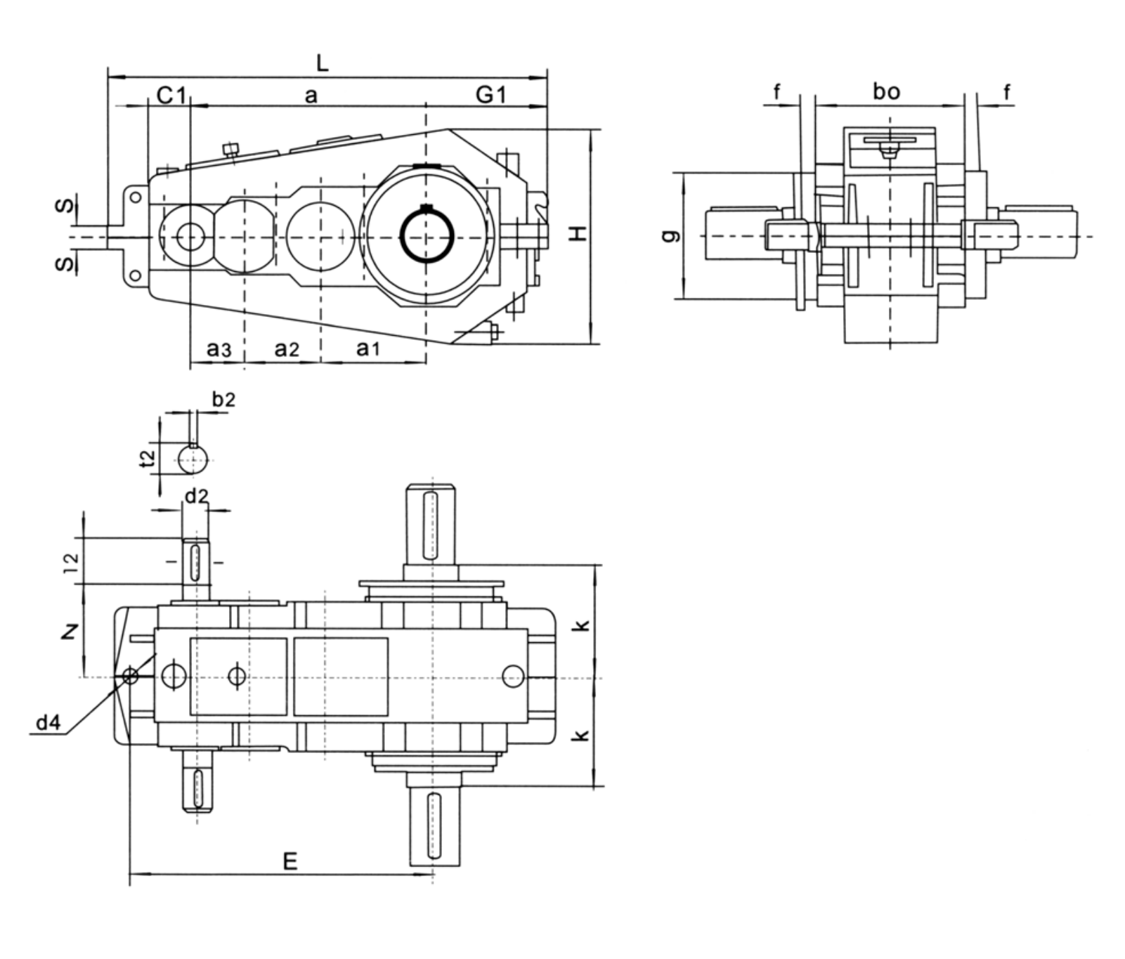
Use the QY3S dimensional drawing to validate the installation envelope, shaft interfaces, mounting features and clearances on the actual machine.
Integrate
Match the selected drive with the connected motor, brake, coupling and supporting crane structure. Treat fit and control as one application.
Maintain
Plan access for lubrication, seals, inspection and removal. A compatible gearbox should also be practical to service after the crane is installed.
Retaining an older hoist mounting
The existing steel support layout may be expensive to modify. Start with the driven centerline and bracket datum locations, then see whether the selected EP-QY3S size fits the three support points. Record old-unit shaft heights and the lifting load so the retrofit does not exchange a dimensional problem for a torque problem.
Use in existing crane machinery
- Hoisting mechanisms with stringent three-point location: describe the working load and mechanical interface before defining the reducer or gearmotor variant.
- Crane travel equipment using a separate motor and coupling: describe the working load and mechanical interface before defining the reducer or gearmotor variant.
- Refurbishment where existing support brackets must be retained: describe the working load and mechanical interface before defining the reducer or gearmotor variant.
Prepare a three-support engineering enquiry
- Three support coordinates: include the appropriate drawing, measured value, operating cycle or connection detail.
- Driven centreline elevation: include the appropriate drawing, measured value, operating cycle or connection detail.
- Housing clearance to crane steelwork: include the appropriate drawing, measured value, operating cycle or connection detail.
- Input and output shaft ends: include the appropriate drawing, measured value, operating cycle or connection detail.
- Nominal and actual ratio: include the appropriate drawing, measured value, operating cycle or connection detail.
- Loaded and reversing torque: include the appropriate drawing, measured value, operating cycle or connection detail.
- Coupling type and guard dimensions: include the appropriate drawing, measured value, operating cycle or connection detail.
- Lifting frequency and motor speed: include the appropriate drawing, measured value, operating cycle or connection detail.
Commercial enquiry for the QY3S series
Ever Power can discuss model identification, interface drawings and practical order quantities for the QY3S Crane Gearbox. Confirmed product configuration, lead time and delivery terms belong in the quotation. Trial and mixed-model requests can be assessed against the total order value.
To compare related drive families, explore the industrial drive product range. The company overview explains the supplier context for engineering and procurement enquiries.
Frequently asked questions about EP-QY3S
What measurements are essential for a three-support retrofit?
Send the centre distances between all support features, three reference elevations, input/output shaft coordinates, coupling positions and the installed-clearance envelope. Include the existing ratio and operating loads. A drawing of one flange alone does not capture the QY3S support relationship.
Can EP-QY3S be supplied with a nonstandard shaft?
A shaft-end revision can be discussed after the torque path, bearing reactions and mating hub geometry have been checked. The requested diameter, keyway and extension should be submitted as a drawing; a nominal model number cannot confirm an exact nonstandard interface.
How is the reduction selected for a crane drum?
Calculate the required output speed from drum diameter and lifting speed, then verify the gearbox input speed and real load torque. Select the listed QY3S ratio and centre distance together, and account for starting and reversing duty.
Can a first-order crane reducer be ordered in only one or two pieces for EP-QY3S?
Small orders of 1–2 pieces may be considered at a higher unit price. A new buyer can ask about 1–5 sample units where the engineering and production arrangement is suitable. MOQ is flexible by configuration; mixed-model orders are welcome when the total order value is approximately USD 1,500 or more. For this product, quote preparation should also address three-point support integrity and gearbox interface placement and the requested quantity.
What production schedule and Incoterms should be used for planning for EP-QY3S?
Indicative production windows are 10–25 working days for standard units, 20–45 for customized components and 45–120 for project equipment. Confirm the date in the accepted quotation. EXW, FOB, CIF and DAP are commonly discussed; FCA, CFR, CPT, CIP and DDP can be reviewed for the actual destination and contract. Schedule confirmation follows review of the QY3S interface and duty requirements.
Discuss a three-support gearbox replacement
Share the support drawing and operating duty for an EP-QY3S configuration. Ever Power can review the centre distance, shaft arrangement and selected ratio with your crane engineering team before the quotation is finalized.