


EP-QSC Vertical Integrated Crane Gearmotor is specified for vertical crane installation, ratio ratings and motor integration. QSC is a dedicated crane gearmotor family with five listed frames and a product-specific interface schedule. Its operating-point selection cannot be reduced to picking the tallest enclosure or matching a motor nameplate. The dimensional table identifies QSC10, QSC12, QSC16, QSC20 and QSC25, with mounting dimensions, connection features and mass. The gearbox and motor arrangement must be checked together against the selected machine design and available space.
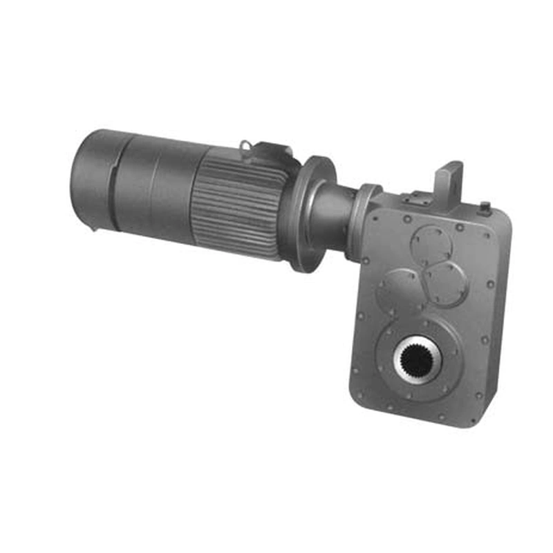
The QSC power and torque schedules present multiple ratio columns and more than one duty level. These values must be linked to the exact frame and operating basis before being used as an equipment rating. Buyers should request the finalized duty point and manufacturer-confirmed selection values rather than copying the maximum torque appearing in one schedule row. Actual gearbox geometry, connected output components and thermal requirements all influence the correct proposal.
QSC machine-matching framework
QSC motor and spline integration review
For an EP-QSC installation, the main decision concerns vertical crane installation, ratio ratings and motor integration. Motor arrangement, spline engagement and duty level must be agreed together for a QSC package. The best starting point is the actual machine arrangement, the operating load and the requested output speed.
Select
Confirm the true mechanical work point for QSC Vertical Crane Gearmotor: input speed, demanded output torque and the dynamic events that govern component loading.
Measure
Use the QSC dimensional drawing to validate the installation envelope, shaft interfaces, mounting features and clearances on the actual machine.
Integrate
Match the selected drive with the connected motor, brake, coupling and supporting crane structure. Treat fit and control as one application.
Maintain
Plan access for lubrication, seals, inspection and removal. A compatible gearbox should also be practical to service after the crane is installed.
Re-equipping an existing QSC drive
Record the old frame, output spline, motor arrangement and speed schedule. The new unit must match structural clearance, electrical interface and required torque at the selected ratio. Use a current assembly drawing for the supplied configuration.
QSC equipment replacement considerations
- Vertical-space-constrained crane transport machinery: describe the working load and mechanical interface before defining the reducer or gearmotor variant.
- Gantry crane mechanisms with an integrated gearbox and motor: describe the working load and mechanical interface before defining the reducer or gearmotor variant.
- Maintenance replacement of QSC-tagged drives with spline interface: describe the working load and mechanical interface before defining the reducer or gearmotor variant.
QSC drive package quotation details
QSC specification and model identification
QSC Vertical Crane Gearmotor selection is defined by the combination of family construction, operating point and machine interfaces. The following data identifies the documented product family; a specific configuration must still be checked against its dimensional drawing and duty schedule.
| Parameter | Series-level reference |
|---|---|
| Frame numbers | QSC10, QSC12, QSC16, QSC20, QSC25 |
| Nominal ratio schedule | 22.4–160 across the rating table |
| Frame dimensional schedule | Includes overall dimensions, connection diameters and weight |
| Spline interface | Dedicated spline data for QSC10–QSC25 |
| Motor arrangement | Verify orientation from approved assembly drawing |
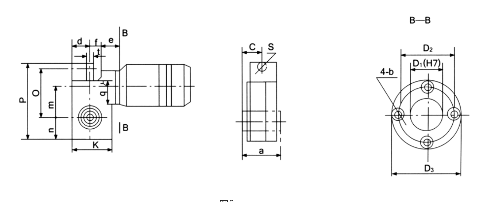
QSC frame envelope by dimension code
| Frame | a (mm) | c (mm) | d (mm) | e (mm) | f (mm) | k (mm) | m (mm) | n (mm) | o (mm) | p (mm) | Mass (kg) |
|---|---|---|---|---|---|---|---|---|---|---|---|
| QSC10 | 208 | 104 | 137 | 40 | 125 | 274 | 225 | 127 | 325 | 490 | 72.25 |
| QSC12 | 255 | 127.5 | 173 | 45 | 150 | 346 | 280 | 160 | 406 | 612 | 141.32 |
| QSC16 | 264 | 132 | 200 | 55 | 180 | 400 | 355 | 220 | 485 | 760 | 210 |
| QSC20 | 318 | 159 | 250 | 55 | 220 | 500 | 470 | 250 | 625 | 930 | 350 |
| QSC25 | 356.5 | 178.25 | 310 | 75 | 275 | 620 | 580 | 310 | 777 | 1160 | 820 |

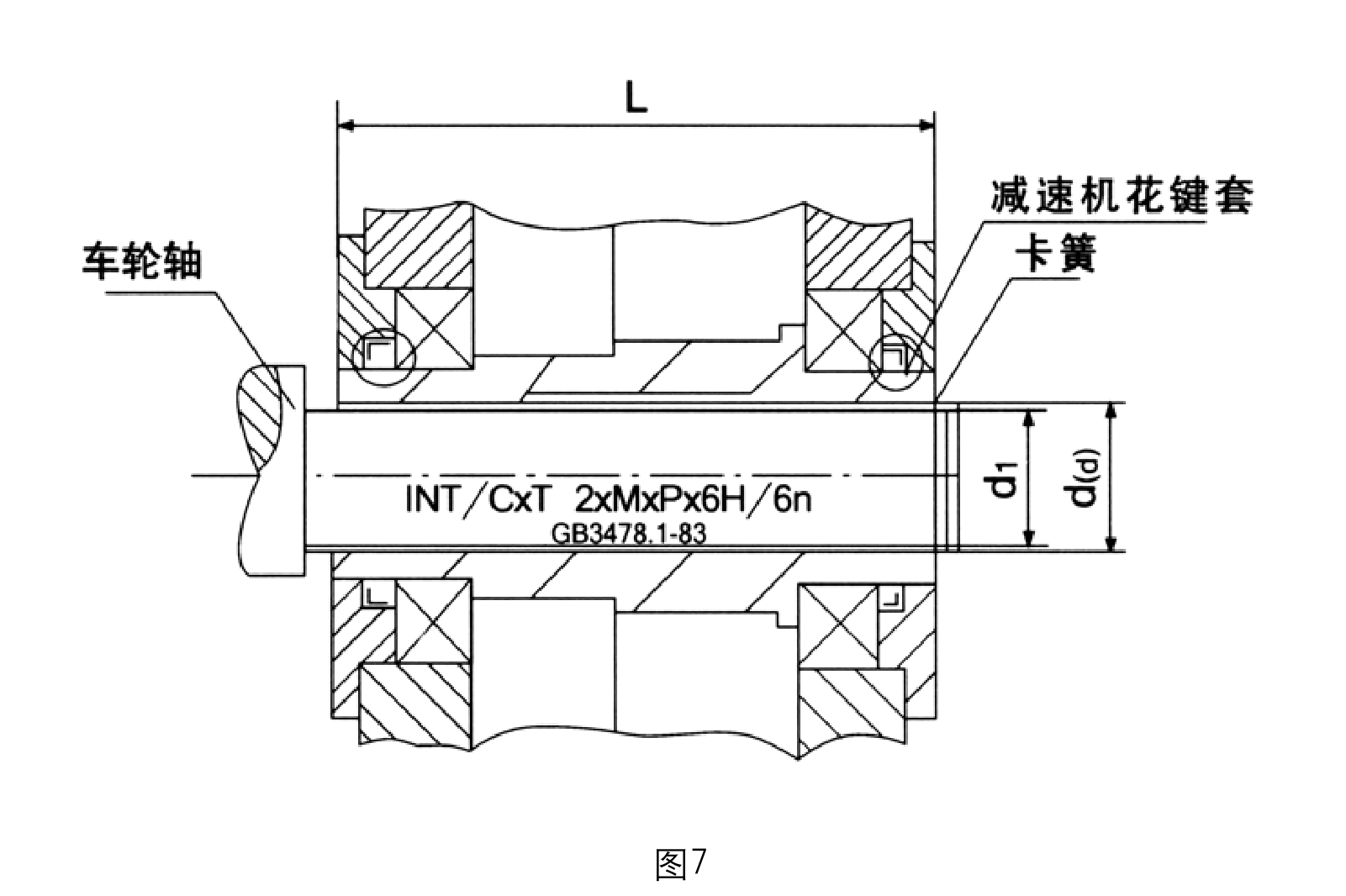
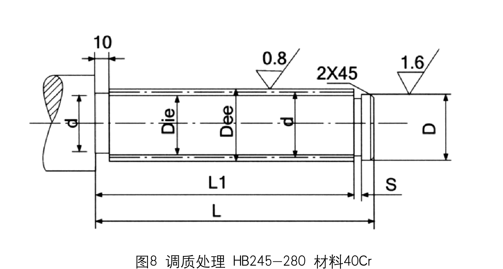
QSC output mating spline information
| Frame | Spline designation | Major dia (mm) | Minor dia (mm) | L (mm) | L1 (mm) | d (mm) | s (mm) |
|---|---|---|---|---|---|---|---|
| QSC10 | INT/EXT31Z×2M×30P×6H/6h | 64 | 59 | 215 | 208 | 57 | 2.2 |
| QSC12 | INT/EXT27Z×3M×30P×6H/6h | 84 | 76.5 | 262 | 255 | 75 | 2.7 |
| QSC16 | INT/EXT35Z×2M×30P×6H/6h | Not specified | Not specified | 272 | 264 | Not specified | Not specified |
| QSC20 | INT/EXT35Z×2M×30P×6H/6h | 108 | 100.5 | 326 | 318 | 96.5 | 2.7 |
| QSC25 | INT/EXT35Z×2M×30P×6H/6h | Not specified | Not specified | 365 | 365.5 | Not specified | Not specified |

Duty rating interpretation
The specification schedules use ratio-dependent permissible power and output torque rather than one universal torque number. Verify whether the relevant rating is continuous, intermittent or linked to a particular duty assumption. Do not compare two configurations solely by the highest number printed in the table.
Motor mounting orientation
Confirm the physical motor axis and housing orientation from a fully dimensioned assembly drawing for the actual configuration. Representative pictures may show different views or arrangements. This confirmation prevents conflicts with cable entry, fan clearance, crane-frame obstructions and removal access.
Frame mass and dimensions
QSC10 through QSC25 differ substantially in casing dimensions and mass. Confirm the available installation space and structural support for the selected drive, including withdrawal clearance and any adjacent cable tray or wheel support. A crane trolley may tolerate an equivalent output speed but not a change in the motor housing envelope.
Spline engagement
A QSC spline specification should include tooth count, module, pressure angle, fit, major/minor diameter and usable engaged length as applicable. Mating shaft details must match the selected frame. Some larger-frame entries have incomplete dimensional cells and should be resolved in the order drawing, not filled from a smaller model by assumption.

Exchange and upgrade project
When a QSC nameplate is unavailable, provide measured shaft and mount dimensions with photographs of the complete installed assembly. Explain whether only the reduction unit is being replaced or the entire motor-plus-gearbox package. The quotation should state clearly which items are included and any interface changes proposed.
Acceleration and impact
A gearmotor on a crane must be checked under accelerating inertia and reversing events as well as steady output torque. Describe the actual motor control method, intended acceleration time, load spectrum, number of starts and connected shaft forces. A simple ratio match is insufficient for an operational replacement.
Heat and service access
The motor and gearbox can share a constrained installation envelope, so cooling paths and service access both matter. Confirm the ambient environment, maintenance intervals, lubricant arrangement and potential contamination. The final design should permit inspection of seals and electrical terminals without requiring unsafe dismantling of neighboring equipment.
- Qsc frame and ratio: include the appropriate drawing, measured value, operating cycle or connection detail.
- Output torque under both duty levels: include the appropriate drawing, measured value, operating cycle or connection detail.
- Motor axis and mounting drawing: include the appropriate drawing, measured value, operating cycle or connection detail.
- Spline tooth and fit specification: include the appropriate drawing, measured value, operating cycle or connection detail.
- Electric supply and speed control: include the appropriate drawing, measured value, operating cycle or connection detail.
- Crane reversing/starting cycle: include the appropriate drawing, measured value, operating cycle or connection detail.
- Environment and cooling clearance: include the appropriate drawing, measured value, operating cycle or connection detail.
- Replacement scope: motor and reducer or reducer only: include the appropriate drawing, measured value, operating cycle or connection detail.
Commercial enquiry for the QSC series
Ever Power can discuss model identification, interface drawings and practical order quantities for the QSC Vertical Crane Gearmotor. Confirmed product configuration, lead time and delivery terms belong in the quotation. Trial and mixed-model requests can be assessed against the total order value.
To compare related drive families, explore the industrial drive product range. The company overview explains the supplier context for engineering and procurement enquiries.
Frequently asked questions about EP-QSC
Why must QSC torque be selected by ratio?
The QSC table associates permissible power and output torque with each frame and nominal ratio, including different duty levels. An isolated maximum value does not identify the rating at the actual operating point.
Can the supplied QSC image establish the exact motor direction?
A representative image cannot substitute for the final assembly drawing. Please confirm the installation orientation, motor axis, cable and fan clearances, and output shaft location for the specific build.
What if the spline table has blank fields for my frame?
Do not extrapolate missing major or minor diameters from another frame. Provide the mating shaft drawing and request a confirmed interface design before order approval.
Can a distributor combine several reducer models in a trial shipment for EP-QSC?
Yes, mixed model quantities may be assessed together against an approximate USD 1,500 minimum order value. A new distributor can ask for 1–5 trial pieces when practical. Very small requests of 1–2 units may be accepted, but should be priced as a small production batch rather than standard-volume procurement. For this product, quote preparation should also address vertical crane installation, ratio ratings and motor integration and the requested quantity.
When could an engineered crane reducer be delivered for EP-QSC?
The schedule depends on the confirmed drawing and production route: standard products typically require 10–25 working days, custom components 20–45 and project-scale equipment 45–120. These are planning ranges, not a promised ship date. Normal trade terms include EXW, FOB, CIF and DAP, with FCA, CFR, CPT, CIP and DDP subject to agreement. Schedule confirmation follows review of the QSC interface and duty requirements.
Check a QSC integrated crane gearbox application
Send the motor details, output spline drawing, ratio requirement and duty cycle for an EP-QSC engineering discussion. We can define the required package and review dimensional compatibility before quotation.