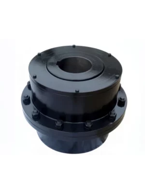
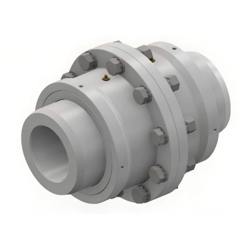
WG Drum Shape Gear Coupling — Type I & Type II
High-rigidity, compact crowned-tooth gear coupling with built-in lubrication port. The foundation of the WG family — 24 sizes, two construction types, massive torque range, and Z1 taper bore option.
Torque Range
0.71 – 1250 KN·m
Product Overview
The WG drum shape gear coupling is a heavy-duty, high-rigidity crowned-tooth gear coupling built for the most demanding horizontal shaft drive applications in mining, steel, power generation, cement, and bulk material handling. It is the base coupling of the WG family — sharing its core gear mesh geometry with the WGP (brake disc), WGC (vertical installation), WGZ (brake drum), and WGT (intermediate shaft) variants.
What sets the WG apart from other drum shape gear coupling series is its combination of two distinct construction types, a wide 24-size range spanning three orders of magnitude in torque capacity, and a built-in lubrication port that enables field re-lubrication without coupling disassembly.
Technical Definition and Working Principle
What Makes the WG a Drum Shape Coupling
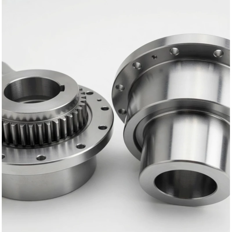
The WG is a moveable rigid coupling that transmits torque through two crowned (barrel-shaped) gear meshes — one on each side of the coupling. Each coupling half consists of a hub with external crowned teeth and a sleeve with internal straight teeth. Torque flows: shaft → hub (crowned external teeth) → sleeve (straight internal teeth) → opposite hub → opposite shaft.
The crown radius machined into each external tooth profile is the defining technical feature that distinguishes the WG from a straight-tooth gear coupling. In a straight-tooth design, torque is transmitted through a line contact running the full tooth width — when shaft angular misalignment is present, this contact shifts to the tooth edge, generating stress concentrations that cause accelerated wear.
The WG's built-in lubrication port on the outer sleeve is a practical engineering detail that separates it from couplings requiring partial disassembly for lubrication. Grease or oil is injected directly into the gear mesh space through the nipple port with the coupling stationary — no sleeve removal required.
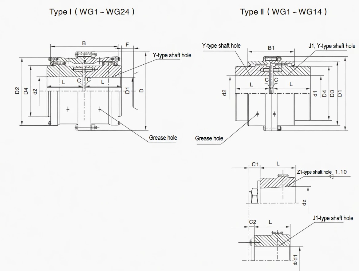
Type I vs Type II Construction
The WG is offered in two structural variants for WG1 through WG14: Type I features a single continuous outer sleeve, while Type II incorporates an inner bore collar with longer hub engagement length for applications requiring greater bore depth or higher interference fit area.
- Type I (WG1–WG24): Standard single outer sleeve configuration. The outer sleeve spans both hubs continuously, providing a compact overall length B. This is the most widely used configuration for standard horizontal industrial drives.
- Type II (WG1–WG14): Features a split or flanged sleeve arrangement with an additional B1 hub engagement length. The Type II provides greater axial retention of each hub within the sleeve and is preferred in applications with frequent torque reversals, higher vibration, or elevated shock loading where the additional B1 engagement reduces the risk of hub axial displacement.
For WG15 through WG24 — the largest sizes — only Type I is available, as the outer dimensions make the Type II split construction impractical. These large sizes serve the heaviest mining and steel mill applications.
Comparison with Other Coupling Types
| Feature |
WG (this product) |
Jaw Coupling |
Disc Coupling |
Rigid Flange |
| Torque Range |
0.71–1250 KN·m |
Low–Medium |
Medium |
High |
| Angular Misalignment |
1.0–1.5 deg per mesh |
Up to 1 deg |
Up to 1 deg |
Near zero |
| Shock Load Tolerance |
Excellent |
Good (elastomer) |
Poor |
Transmitted fully |
| Z1 Taper Bore |
Yes — standard option |
Limited |
No |
No |
| Built-in Lubrication Port |
Yes — standard |
No (no lube) |
No |
No |
| Axial Displacement |
Yes (built-in) |
Limited |
Yes |
No |
| Two Construction Types |
Yes — Type I & Type II |
No |
No |
No |
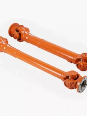
WG vs WGP vs WGC vs WGZ vs WGT — Which Variant Is Right for You?
All five WG-family variants share the WG crowned gear mesh as their core transmission element. The choice between them depends on your application's braking requirements, shaft orientation, and shaft spacing.
| Feature |
WG |
WGP |
WGC |
WGZ |
WGT |
| Full Name |
Standard drum gear coupling |
With brake disc (flat disc) |
Vertical installation type |
With brake drum (cylindrical) |
With intermediate sleeve (spacer) |
| Standard |
JB/T8854.2 / JB/ZQ4186 |
JB/T7001 |
JB/T7002-93 |
JB/T7003-93 |
JB/T7004 |
| Braking Feature |
None |
Flat brake disc for caliper brakes |
None |
Cylindrical drum for shoe brakes |
None |
| Shaft Orientation |
Horizontal |
Horizontal |
Vertical — purpose designed |
Horizontal |
Horizontal |
| Intermediate Shaft |
No |
No |
No |
No |
Yes — for distant shafts |
| Number of Sizes |
24 (WG1–WG24) |
14 (WGP1–WGP14) |
14 (WGC1–WGC14) |
14 (WGZ1–WGZ14) |
24 (WGT1–WGT24) |
| Lubrication Port |
Yes |
Yes |
Yes |
Yes |
Yes |
| Choose When... |
Standard horizontal drive, no braking needed |
Caliper braking required (e.g. crane hoists, VFD drives) |
Vertical shaft drive (pumps, fans, agitators) |
Shoe brake system required (hoists, cranes) |
Motor and gearbox are far apart, or axle withdrawal needed |
Specifications & Size Matrix — WG1 to WG24
All specifications are from the WG product catalogue per JB/T8854.2 and JB/ZQ4186. Dimensions in millimetres. Where two values appear for C and weight, the first is Type I and the second is Type II. WG15–WG24 are Type I only.
WG1 – WG12 Specifications (Type I and Type II)
| Type |
Torque
(N·m) |
Speed
(rpm) |
Shaft Bore d1,d2,dz
(mm) |
Y |
J1, Z1 |
D |
D1 |
D2 |
D3 |
D4 |
B |
B1 |
F |
Inertia I
(Kg·m²) |
Inertia II
(Kg·m²) |
Weight I
(Kg) |
Weight II
(Kg) |
| WG1 |
710 |
7500 |
12–42 |
32–112 |
–/44/84 |
122 |
115 |
98 |
88 |
60 |
116 |
100 |
30 |
0.008 |
0.0063 |
5.6 |
4.86 |
| WG2 |
1250 |
6700 |
22–56 |
52–112 |
–/60/84 |
150 |
145 |
118 |
108 |
77 |
136 |
104 |
30 |
0.021 |
0.016 |
9.78 |
7.48 |
| WG3 |
2500 |
6300 |
22–63 |
52–142 |
–/60/107 |
170 |
165 |
140 |
125 |
90 |
160 |
108 |
30 |
0.047 |
0.033 |
16.7 |
12.2 |
| WG4 |
4500 |
5600 |
30–80 |
82–172 |
–/84/132 |
200 |
195 |
160 |
145 |
112 |
180 |
116 |
30 |
0.098 |
0.073 |
25.6 |
19.6 |
| WG5 |
7100 |
5300 |
30–90 |
82–172 |
–/84/132 |
225 |
215 |
180 |
168 |
128 |
200 |
126 |
30 |
0.175 |
0.126 |
35 |
26.1 |
| WG6 |
10000 |
5000 |
32–100 |
82–212 |
–/107/167 |
245 |
230 |
200 |
185 |
145 |
224 |
134 |
30 |
0.295 |
0.213 |
51.6 |
38 |
| WG7 |
14000 |
4500 |
32–110 |
82–212 |
–/107/167 |
272 |
265 |
230 |
210 |
160 |
244 |
148 |
30 |
0.53 |
0.35 |
68.6 |
45 |
| WG8 |
20000 |
4250 |
55–125 |
112–212 |
–/107/167 |
290 |
272 |
245 |
225 |
176 |
272 |
162 |
30 |
0.71 |
0.46 |
79.5 |
55.8 |
| WG9 |
25000 |
4000 |
65–140 |
142–252 |
107/202 |
315 |
305 |
265 |
245 |
190 |
280 |
176 |
30 |
1.05 |
0.77 |
106.5 |
80.5 |
| WG10 |
40000 |
3550 |
75–160 |
142–302 |
107/242 |
355 |
340 |
300 |
280 |
225 |
330 |
196 |
30 |
1.87 |
1.54 |
158.8 |
121.8 |
| WG11 |
56000 |
3000 |
85–180 |
172–302 |
132/242 |
412 |
385 |
345 |
325 |
256 |
360 |
224 |
40 |
3.66 |
2.77 |
214 |
167 |
| WG12 |
80000 |
2800 |
120–200 |
212–352 |
167/282 |
440 |
435 |
375 |
360 |
288 |
414 |
250 |
40 |
6.39 |
4.75 |
302 |
142 |
WG13 – WG24 Specifications (Type I Only)
| Type |
Torque
(N·m) |
Speed
(rpm) |
Bore Range
(mm) |
Y Range |
D |
D2 |
D4 |
B |
F |
Inertia I
(Kg·m²) |
Weight I
(Kg) |
| WG13 |
112000 |
2500 |
140–220 |
252–352 |
490 |
425 |
320 |
470 |
50 |
10.44 |
390 |
| WG14 |
160000 |
2300 |
160–260 |
302–410 |
545 |
462 |
362 |
530 |
50 |
17.46 |
522 |
| WG15 |
224000 |
2100 |
160–270 |
302–470 |
580 |
488 |
400 |
560 |
50 |
24.91 |
677 |
| WG16 |
280000 |
1900 |
180–300 |
302–470 |
650 |
560 |
440 |
600 |
50 |
43.22 |
939 |
| WG17 |
355000 |
1800 |
200–320 |
352–470 |
690 |
600 |
460 |
650 |
50 |
56.27 |
1041 |
| WG18 |
450000 |
1700 |
220–360 |
352–550 |
750 |
650 |
510 |
700 |
60 |
88.17 |
1381 |
| WG19 |
560000 |
1600 |
240–380 |
410–550 |
775 |
690 |
535 |
745 |
60 |
108.8 |
1526 |
| WG20 |
710000 |
1500 |
260–400 |
410–650 |
825 |
730 |
580 |
785 |
60 |
164.4 |
2081 |
| WG21 |
800000 |
1300 |
280–440 |
470–650 |
925 |
825 |
620 |
810 |
60 |
242.7 |
2460 |
| WG22 |
900000 |
950 |
320–460 |
470–650 |
950 |
850 |
665 |
820 |
60 |
297 |
2775 |
| WG23 |
1000000 |
900 |
360–500 |
550–650 |
1030 |
900 |
710 |
880 |
60 |
384.8 |
3148 |
| WG24 |
1250000 |
850 |
380–520 |
550–800 |
1060 |
925 |
730 |
900 |
70 |
477.8 |
3766 |
Note: Torque values are in N·m (divide by 1000 for KN·m). Y column shows the bore length range for Y type shaft holes. J1/Z1 bore lengths are longer — refer to catalogue table C1/C2 values. Type II data applies to WG1–WG14 only.
Custom Bore, Type Selection & Shaft Fit Available
Need a specific Y, J1, or Z1 bore diameter not listed in the standard range, a custom keyway, or Type II construction for a larger size? Our engineering team evaluates custom requests and provides solutions. Contact us.
Technical Advantages — Why Crowned Tooth Outperforms Straight Tooth
Longer Service Life Under Shock Loads
Crusher and mill drives experience torsional shock peaks of 2–4× nominal torque during material ingestion and blockage events. The WG's crowned tooth distributes these peaks as a Hertzian contact patch rather than concentrating them at a tooth edge — significantly reducing peak tooth stress under shock loading.
Reduced Bearing Loads
A misaligned straight-tooth coupling generates cyclic bending moments at 2× running frequency, loading motor and gearbox bearings with parasitic radial forces that accelerate bearing fatigue. The WG's crowned tooth self-centres under load, generating substantially lower parasitic radial force transmission.
Lower Maintenance Frequency — With Built-In Lubrication Port
The WG's lubrication port is more than a convenience — it fundamentally changes the maintenance workflow. Re-lubrication requires only the injection of fresh grease through the port with the coupling stationary — no guards to remove, no sleeve to pull, no shaft disassembly. This directly translates to shorter planned maintenance windows and fewer unplanned outages from lubrication-related failures.
Suitable for High-Speed Applications
WG1 is rated to 7500 RPM — the highest speed in the drum shape gear coupling family — making it suitable for direct 2-pole motor coupling on 50 Hz supplies. The crowned tooth profile generates significantly less heat at speed by avoiding the scrubbing action of edge-loaded straight teeth under misalignment.
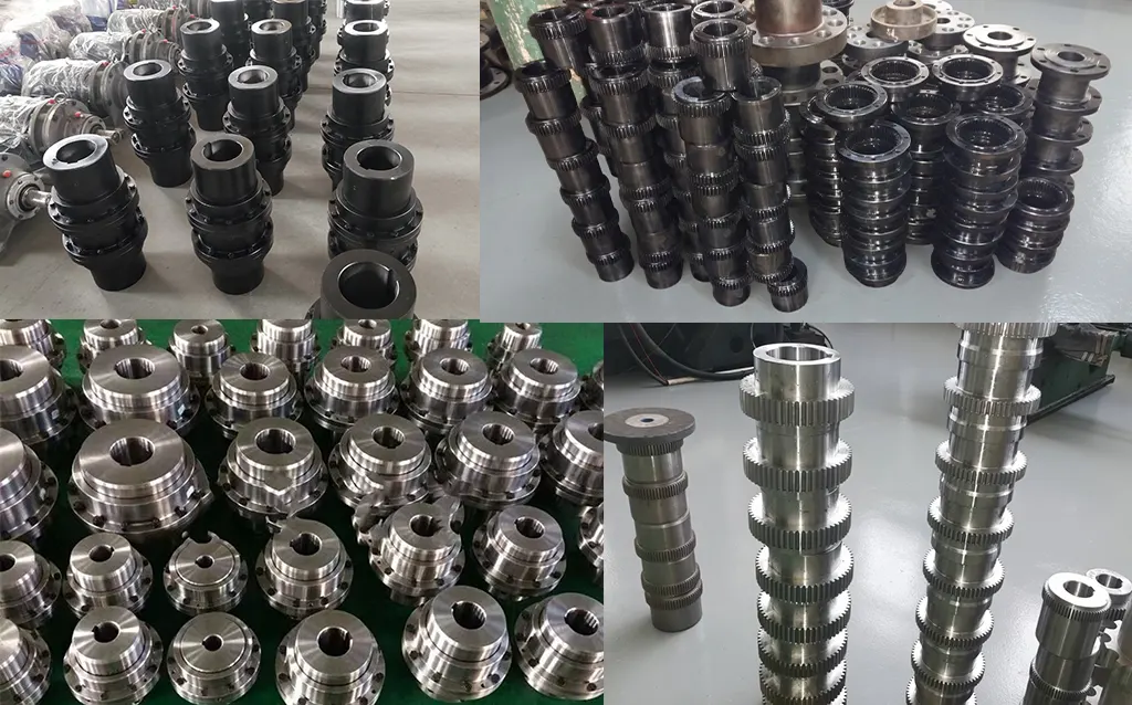
Manufacturing & Quality Assurance
Manufacturing Process
WG couplings are manufactured from forged alloy steel blanks — 42CrMo4 for WG8 and above, 45# carbon steel for smaller sizes. The crowned external tooth profiles are CNC hobbed to DIN Class 7 accuracy or better, with tooth flanks carburised and quenched to 58–62 HRC surface hardness.
The lubrication port is drilled and tapped after all machining is complete, with thread-form verified for compatibility with standard grease nipple specifications. All bores are finish-machined to H7 or js6 tolerance after heat treatment.
Quality Control Flow
STEP 1
Incoming Material & Chemistry Verification
STEP 2
CNC Hobbing & Bore Machining
STEP 3
Carburising & Quench Hardening
STEP 4
CMM Inspection, Tooth Profile & Hardness
STEP 5
Lubrication Port Fitting, Painting & Pack
Certifications
ISO 9001:2015 quality management certification covers all WG manufacturing operations from raw material receipt through to finished goods dispatch. CE marking applies to applicable sizes. Products manufactured to JB/T8854.2 and JB/ZQ4186.
Why Source Your WG Couplings from RP?