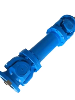
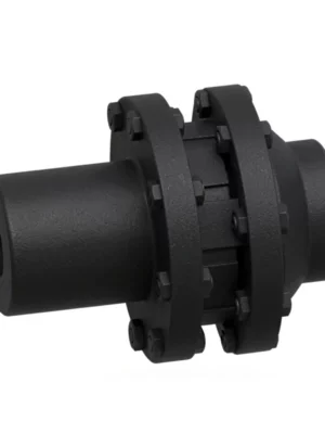
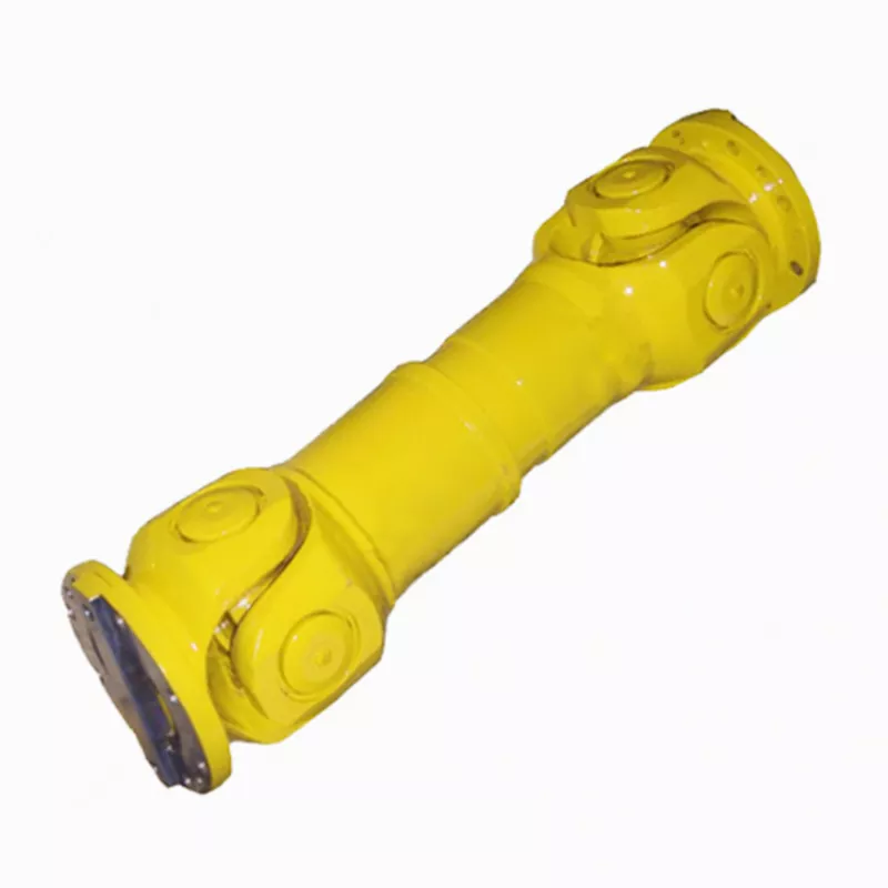
SWP-F Long Large Flexible Universal Joint Couplings — Product Overview
The SWP-F Long Large Flexible Universal Joint Coupling is engineered for applications where standard telescoping stroke is insufficient. While SWP-A provides Ls of 50–230 mm, the SWP-F delivers Ls of 150–380 mm at equivalent gyration diameters — 2 to 3 times the stroke capacity at the same torque rating.
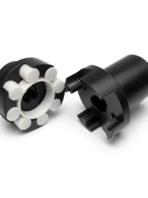
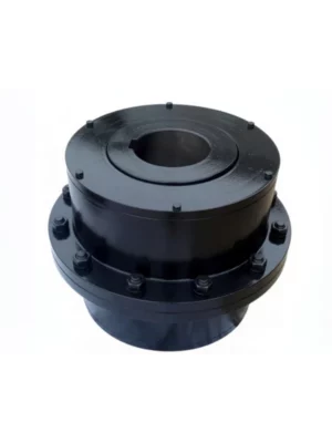
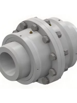
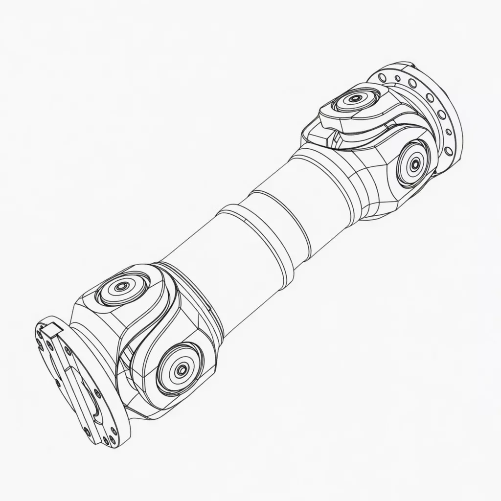
Structurally, SWP-F retains all the hallmarks of the SWP series: split axletree bearing housing for in-situ spider replacement, cross-spider Hooke's joint mechanism, and the full torque rating of equivalent diameter types. The difference lies in the extended spline engagement length of the telescoping sleeve, enabling the greater stroke range.
Where standard SWP-A stroke is insufficient: Hot rolling mill primary spindles routinely require roll change extraction distances of 150–300 mm as the work roll is withdrawn axially from the roll stand. If this extraction distance exceeds the SWP-A Ls for your diameter, SWP-F is the required solution.
Tube mill and pipe mill applications: Mandrel bars in seamless tube mills travel axially while torque is transmitted through the spindle coupling. The large telescoping stroke of SWP-F accommodates the full mandrel travel distance without the coupling reaching its end-stop during operation.
These operations typically use European or Japanese-manufactured rolling mills that specify large-stroke spindle couplings — SWP-F provides the compatible supply chain alternative with equivalent dimensional accuracy.
Technical Specifications
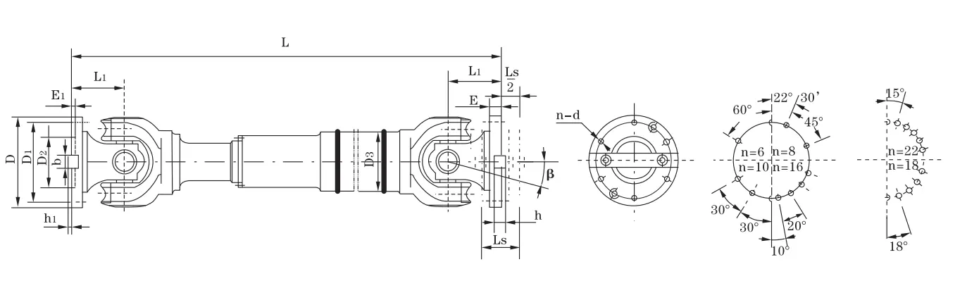
| Type |
D (mm) |
Tn (kN·m) |
Tf (kN·m) |
Ls (mm) |
β |
Lmin (mm) |
D1 js11 |
D2 H7 |
D3 |
E |
E1 |
b×h |
h1 |
L1 |
n–d |
I Lmin (kg·m²) |
ΔI/100mm |
G Lmin (kg) |
ΔG/100mm |
| SWP160F |
160 |
16 |
8 |
150 |
≤10 |
770 |
140 |
95 |
114 |
15 |
4 |
20×12 |
6 |
85 |
6–13 |
0.14 |
0.0059 |
51 |
2.1 |
| SWP180F |
180 |
20 |
10 |
170 |
≤10 |
830 |
155 |
105 |
121 |
15 |
4 |
24×14 |
7 |
95 |
6–15 |
0.23 |
0.0072 |
64 |
2.3 |
| SWP200F |
200 |
31.5 |
16 |
190 |
≤10 |
950 |
175 |
125 |
127 |
17 |
5 |
28×16 |
8 |
110 |
8–15 |
0.4 |
0.0114 |
88 |
3.4 |
| SWP225F |
225 |
40 |
20 |
210 |
≤10 |
1070 |
196 |
135 |
152 |
20 |
5 |
32×18 |
9 |
130 |
8–17 |
0.66 |
0.029 |
120 |
6.6 |
| SWP250F |
250 |
63 |
31.5 |
220 |
≤10 |
1110 |
218 |
150 |
168 |
25 |
5 |
40×25 |
12.5 |
135 |
8–19 |
1.06 |
0.0407 |
158 |
7.3 |
| SWP285F |
285 |
90 |
45 |
240 |
≤10 |
1270 |
245 |
170 |
194 |
27 |
7 |
40×30 |
15 |
150 |
8–21 |
2.24 |
0.0702 |
255 |
9.4 |
| SWP315F |
315 |
140 |
63 |
270 |
≤10 |
1410 |
280 |
185 |
219 |
32 |
7 |
40×30 |
15 |
170 |
10–23 |
3.99 |
0.1144 |
344 |
12.0 |
| SWP350F |
350 |
180 |
90 |
290 |
≤10 |
1540 |
310 |
210 |
245 |
35 |
8 |
50×32 |
16 |
185 |
10–23 |
6.9 |
0.1663 |
460 |
13.6 |
| SWP390F |
390 |
250 |
112 |
315 |
≤10 |
1680 |
345 |
235 |
273 |
40 |
8 |
70×36 |
18 |
205 |
10–25 |
11.9 |
0.2695 |
600 |
18.0 |
| SWP435F |
435 |
355 |
160 |
335 |
≤10 |
1880 |
385 |
255 |
299 |
42 |
10 |
80×40 |
20 |
235 |
16–28 |
22.41 |
0.3645 |
985 |
20.0 |
| SWP480F |
480 |
450 |
224 |
350 |
≤10 |
2000 |
425 |
275 |
351 |
47 |
12 |
90×45 |
22.5 |
265 |
16–31 |
39.09 |
0.7028 |
1356 |
28.0 |
| SWP550F |
550 |
710 |
315 |
360 |
≤10 |
2230 |
492 |
320 |
402 |
50 |
12 |
100×45 |
22.5 |
290 |
16–31 |
62.12 |
1.1842 |
1785 |
35.7 |
| SWP600F |
600 |
1000 |
500 |
370 |
≤10 |
2800 |
544 |
380 |
450 |
55 |
15 |
90×55 |
27.5 |
360 |
22–34 |
100.48 |
1.7159 |
2403 |
40.5 |
| SWP640F |
640 |
1250 |
630 |
380 |
≤10 |
2920 |
575 |
385 |
480 |
60 |
15 |
100×60 |
30 |
385 |
18–38 |
168.28 |
2.308 |
3207 |
48.3 |
Note: D=315mm, L=1600mm → SWP315F×1600. Ls = large telescoping stroke (150–380 mm); significantly greater than SWP-A at the same diameter. ΔI and ΔG are incremental per 100 mm length increase above Lmin.
Industry Applications
Hot Strip Mill Work Roll Change Spindles
Working condition: Work roll change requires axial extraction of 200–350 mm; simultaneous torque transmission up to 1 250 kN·m during rolling; high cycle count for spindle stroke over 20-year service life.
Why SWP-F: SWP-A's maximum stroke of 230 mm (at D640) is insufficient for the roll extraction distances of large-diameter hot strip mill work rolls. SWP-F provides up to 380 mm Ls at D640 — adequate for all standard hot strip mill roll change procedures.
Customer benefit: Roll change completed within coupling stroke — no drivetrain disconnection required. Faster roll change cycle, reduced downtime per shift.
Seamless Tube Mill Mandrel Bar Drives
Working condition: Mandrel bar travels 100–300 mm axially while the mill spindle simultaneously transmits high torque; contaminated environment (scale, water, lubricant).
Why SWP-F: The mandrel bar's axial travel during piercing and sizing operations demands a coupling stroke well beyond standard types. SWP-F's extended Ls keeps the telescoping sleeve within its engagement range throughout the full mandrel travel.
Customer benefit: Roll bearing protection across full mandrel travel range; elimination of the bearing overload failures common when undersized-stroke couplings are specified on mandrel drive applications.
⚙️ Large Rolling Press & Forging Press Drives
Working condition: Eccentric ram motion induces significant axial displacement at the drive coupling point each press cycle; very high torque at low speed.
Why SWP-F: The eccentric rotation of press drive cranks produces cyclic axial displacement at the coupling — SWP-F's large stroke accommodates this without loading the press crankshaft bearings with coupling end-stop forces.
Customer benefit: Extended crankshaft bearing service life; smoother press cycle dynamics; reduced vibration transmitted to the press frame.
Offshore & Heavy Lifting Equipment
Working condition: Winch and crane drives on vessels experience significant axial movement from vessel motion and structural flex; harsh marine environment.
Why SWP-F: The large telescoping stroke absorbs vessel-motion-induced axial displacement at the coupling, preventing the drivetrain from acting as a rigid axial strut that transmits hull deflection forces into the gearbox.
Customer benefit: Drivetrain protected from vessel-flex loads; gearbox bearing service life extended in harsh offshore environments.
How to Choose: SWP-F vs SWP-A Stroke Comparison
The decision between SWP-F and SWP-A hinges on a single question: does your required axial displacement exceed the SWP-A Ls value for your selected diameter? If yes, SWP-F is the correct type.
| Diameter |
SWP-A Ls (mm) |
SWP-F Ls (mm) |
SWP-F Stroke Advantage |
| D160 |
50 |
150 |
+200% stroke |
| D250 |
80 |
220 |
+175% stroke |
| D315 |
110 |
270 |
+145% stroke |
| D480 |
170 |
350 |
+106% stroke |
| D640 |
230 |
380 |
+65% stroke |
Stroke Calculation Guidance
Required Ls = Axial displacement (operational) + Thermal shaft growth + Assembly tolerance + 20% safety margin. For roll change applications: measure actual roll extraction travel distance from your maintenance records, then add thermal growth and a 20% margin.
SWP-F vs SWP-A torque performance: Torque ratings are identical. Tn and Tf values for SWP-F match SWP-A at every diameter. There is no torque penalty for specifying the larger stroke type.
⚠️ Common Errors When Specifying SWP-F
- Using SWP-A where roll extraction stroke exceeds its Ls: A 280 mm roll extraction distance on a D480 spindle cannot be served by SWP480A (Ls=170 mm). Operating at over-stroke compresses the telescoping sleeve against its end stop, transmitting the full extraction force directly to roll bearings — immediate bearing damage results.
- Over-specifying SWP-F where SWP-A stroke suffices: SWP-F is heavier, longer, and more expensive than SWP-A. If SWP-A Ls covers your displacement with a 20% margin, there is no benefit to specifying SWP-F.
- Not accounting for dynamic stroke changes: On tube mill mandrel drives, the stroke varies with tube length being rolled. Verify that the minimum tube length production run does not bring the coupling to the stroke fully-open position, which reduces spline engagement and increases wear rate.
Rolling mill spindle stroke calculation is complex — share your mill geometry and roll change procedure with our engineering team and we will verify the appropriate SWP-F size and length.
Why Choose RP for SWP-F Supply
SWP-F large stroke couplings are manufactured to the same quality standard as all SWP types, with additional specific controls on the extended telescoping sleeve assembly that governs the large stroke performance.
Spline Engineering for Large Stroke
The extended spline engagement length of SWP-F requires precise involute spline geometry to distribute torque evenly across the full engagement range. Our splines are hobbed on CNC gear hobbing machines and verified by CMM to DIN 5480 tolerances.
️ Sealing for Contaminated Environments
The telescoping sleeve of SWP-F uses a labyrinth seal and grease retention band on both ends of the spline engagement zone. For rolling mill applications where scale, water, and rolling oil contamination is severe, we recommend fitting additional external seal covers.
Full Load Testing
SWP-F assemblies in sizes D315 and above can be supplied with a witnessed torque test at 1.5× Tn and a full-stroke cycling test (25 complete compression/extension cycles) before shipment, on request.
Global Delivery Track Record
We supply SWP-F spindle couplings to rolling mills in Asia, Europe, and the Middle East as both OEM replacements and new-build components. Air freight available for urgent rolling mill breakdowns.
Customer Reviews & Case Studies
Our rougher stand spindle couplings had been reaching their Ls end-stop during roll changes — we were hearing the impact on every roll change cycle. RP SWP480F with 350 mm stroke resolved this immediately. Running 18 months with no further incidents.
— Rolling Mill Maintenance Engineer, Steel Plant
Japan — Seamless Tube Mill Mandrel Drive, Osaka ★★★★★
We evaluated SWP-F against two domestic suppliers. RP's dimensional accuracy, spline surface finish, and documentation quality matched our reference test. Price was 22% lower. We will continue ordering from RP for our mandrel drive spindles.
— Procurement Manager, Japanese Tube Mill Operator
Saudi Arabia — Rolling Press Drive, Jubail Industrial City ★★★★☆
Specified SWP350F for a rolling press eccentric drive where the press stroke induced 180 mm axial cycling at the coupling. The previous coupling had a 120 mm stroke and was failing every 3 months. SWP-F has run 14 months without issue.
— Mechanical Engineer, Saudi Arabian Metal Processing Plant
Netherlands — Offshore Crane Drive, North Sea Vessel ★★★★★
We installed SWP285F on a North Sea crane vessel winch drive. The marine-grade surface treatment and large stroke absorbed the vessel-induced axial displacement that had been causing premature gearbox bearing failures. Highly recommended for offshore applications.
— Chief Engineer, Dutch Offshore Crane Vessel Operator
Frequently Asked Questions
What is the maximum telescoping stroke available in SWP-F and how does it compare to SWP-A?
SWP-F provides Ls from 150 mm (D160) to 380 mm (D640). SWP-A provides Ls from 50 mm (D160) to 230 mm (D640). The SWP-F stroke advantage ranges from +200% at small diameters to +65% at D640. choose SWP-F whenever your calculated required stroke exceeds the SWP-A Ls for your diameter.
Does the larger stroke of SWP-F reduce its torque capacity compared to SWP-A?
No. The nominal torque (Tn) and fatigue torque (Tf) values for SWP-F are identical to SWP-A at every gyration diameter. The extended Ls is achieved by lengthening the spline engagement zone, not by reducing the cross-section of load-carrying components.
How should the telescoping sleeve of SWP-F be maintained in high-cycle rolling applications?
In high-cycle applications (multiple roll changes per shift), the telescoping spline is the most maintenance-critical component. Apply grease every 200–300 operating hours in rolling mill service; check spline engagement marks for even contact pattern at each re-greasing. Spider needle bearings: re-grease every 400–600 hours.
Can SWP-F be used in vertical shaft installations?
Yes, with specific lubrication attention. In vertical installations, the telescoping sleeve will tend to fully compress or extend under coupling weight unless the connected shafts are properly supported. Ensure the telescoping sleeve remains in the mid-stroke position during normal operation to preserve grease distribution across the full spline length.
What is the lead time for SWP-F couplings in sizes above D435?
For sizes D160–D390, semi-finished components are held in stock for assembly within 15 business days. For D435–D550, production time is 4–5 weeks. For D600–D640, 5–7 weeks production time. Air freight available for emergency mill breakdowns.
Request Your SWP-F Large Stroke Coupling Quote
Large Stroke Rolling Mill Spindles — SWP-F Enquiries Welcome
Whether you're upgrading undersized-stroke couplings or specifying new mill spindles, our team will calculate the correct SWP-F size and length for your exact roll change or mandrel travel requirement.
Get Stroke Calculation Review
Request Commercial Quote
ISO 9001:2015 · Rolling Mill Spindle Specialists