SWP-A Long Flexible Universal Joint Couplings — Product Overview
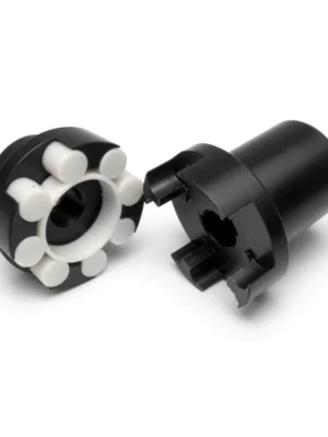
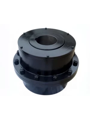
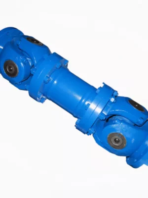
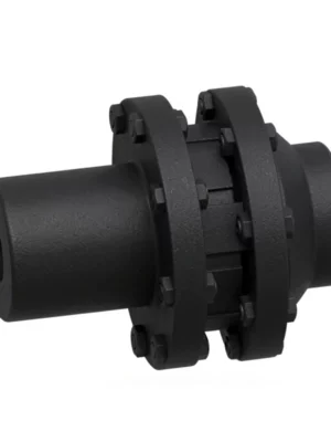
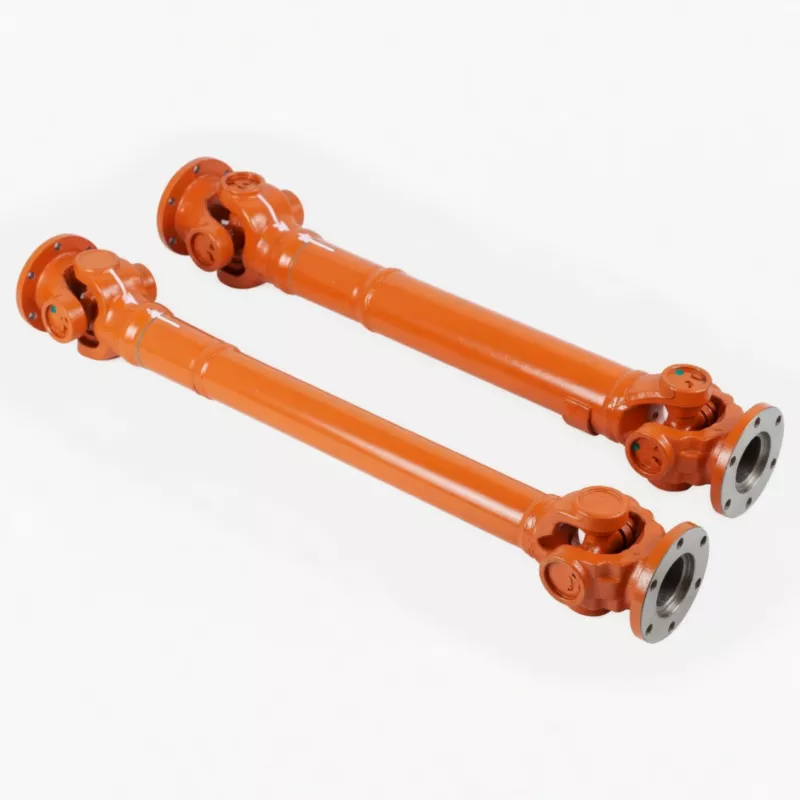
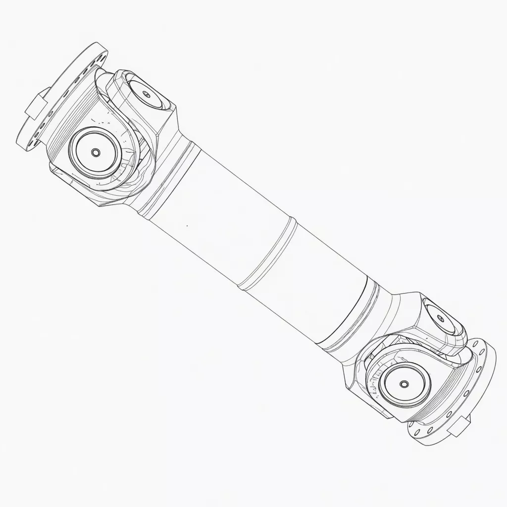
The SWP-A Long Flexible Universal Joint Coupling is a split axletree, spider-type cardan shaft engineered for heavy-duty power transmission between two non-collinear shafts. In contrast to its compact counterpart (SWP-B) or the rigid fixed-length variants (SWP-C/D), the SWP-A pairs an extended overall installation length with a built-in telescoping sleeve that handles axial displacement from 50 mm (D=160) up to 230 mm (D=640). This combined angular and axial compensation makes it the go-to solution whenever shaft centre distances shift under load or thermal growth must be absorbed without passing destructive axial forces into connected bearings.
The coupling functions on the well-established Hooke's joint (Cardan joint) principle: two yokes linked via a cross-shaped spider carry rotation across angular offsets up to ≤10° (types A–F).
Gyration diameters range from 160 mm to 640 mm, with nominal torques spanning 16 kN·m to 1 250 kN·m and fatigue (weary) torques from 8 to 630 kN·m. This spectrum addresses everything from medium mill auxiliary drives through to primary roughing stand drives in hot strip mills.
Technical Specifications
| Type |
D (mm) |
Tn (kN·m) |
Tf (kN·m) |
Ls (mm) |
β |
Lmin (mm) |
D1 js11 |
D2 H7 |
D3 |
E |
E1 |
b×h |
h1 |
L1 |
n–d |
I Lmin (kg·m²) |
ΔI /100mm |
G Lmin (kg) |
ΔG /100mm |
| SWP160A |
160 |
16 |
8 |
50 |
≤10 |
660 |
140 |
95 |
114 |
15 |
4 |
20×12 |
6 |
85 |
6–13 |
0.13 |
0.0055 |
47 |
2.1 |
| SWP180A |
180 |
20 |
10 |
60 |
≤10 |
752 |
155 |
105 |
121 |
15 |
4 |
24×14 |
7 |
95 |
6–15 |
0.22 |
0.0072 |
60 |
2.3 |
| SWP200A |
200 |
31.5 |
16 |
70 |
≤10 |
823 |
175 |
125 |
127 |
17 |
5 |
28×16 |
8 |
110 |
8–15 |
0.37 |
0.0114 |
81 |
3.4 |
| SWP225A |
225 |
40 |
20 |
76 |
≤10 |
933 |
196 |
135 |
152 |
20 |
5 |
32×18 |
9 |
130 |
8–17 |
0.63 |
0.029 |
109 |
6.6 |
| SWP250A |
250 |
63 |
31.5 |
80 |
≤10 |
978 |
218 |
150 |
168 |
25 |
5 |
40×25 |
12.5 |
135 |
8–19 |
1.02 |
0.0407 |
147 |
7.3 |
| SWP285A |
285 |
90 |
45 |
100 |
≤10 |
1133 |
245 |
170 |
194 |
27 |
7 |
40×30 |
15 |
150 |
8–21 |
2.17 |
0.0702 |
241 |
9.4 |
| SWP315A |
315 |
140 |
63 |
110 |
≤10 |
1250 |
280 |
185 |
219 |
32 |
7 |
40×30 |
15 |
170 |
10–23 |
3.86 |
0.1144 |
322 |
12.0 |
| SWP350A |
350 |
180 |
90 |
120 |
≤10 |
1380 |
310 |
210 |
245 |
35 |
8 |
50×32 |
16 |
185 |
10–23 |
6.66 |
0.1663 |
428 |
13.6 |
| SWP390A |
390 |
250 |
112 |
120 |
≤10 |
1495 |
345 |
235 |
273 |
40 |
8 |
70×36 |
18 |
205 |
10–25 |
11.53 |
0.2695 |
566 |
18.0 |
| SWP435A |
435 |
355 |
160 |
150 |
≤10 |
1710 |
385 |
255 |
299 |
42 |
10 |
80×40 |
20 |
235 |
16–28 |
21.81 |
0.3645 |
932 |
20.0 |
| SWP480A |
480 |
450 |
224 |
170 |
≤10 |
1910 |
425 |
275 |
351 |
47 |
12 |
90×45 |
22.5 |
265 |
16–31 |
38.04 |
0.7028 |
1294 |
28.0 |
| SWP550A |
550 |
710 |
315 |
190 |
≤10 |
2135 |
492 |
320 |
402 |
50 |
12 |
100×45 |
22.5 |
290 |
16–31 |
61.28 |
1.1842 |
1744 |
35.7 |
| SWP600A |
600 |
1000 |
500 |
210 |
≤10 |
2580 |
544 |
380 |
450 |
55 |
15 |
90×55 |
27.5 |
360 |
22–34 |
98.63 |
1.7159 |
2330 |
40.5 |
| SWP640A |
640 |
1250 |
630 |
230 |
≤10 |
2685 |
575 |
385 |
480 |
60 |
15 |
100×60 |
30 |
385 |
18–38 |
167.67 |
2.308 |
3153 |
48.3 |
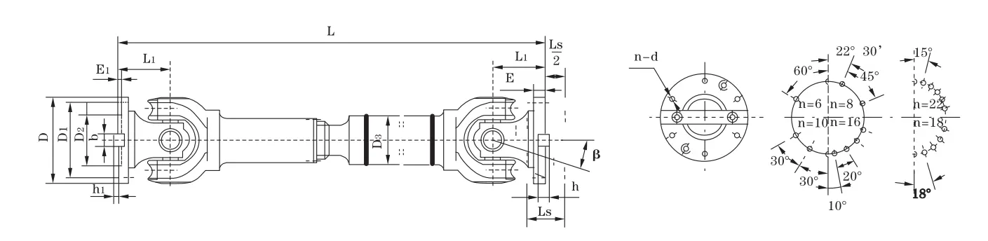
Note: Gyration diameter D=315mm, installation length L=1800mm → SWP315A×1800. All dimensions in mm; Tn = nominal torque; Tf = weary (fatigue) torque; Ls = flex quantity (telescoping stroke); I = rotational inertia; G = weight.
Industry Applications
⚙️ Hot Strip & Plate Rolling Mills
Working condition: Continuous high-torque cycles, thermal elongation of roll necks, frequent roll changes requiring axial withdrawal.
Why SWP-A: The long telescoping stroke (up to 230 mm on D640) handles both thermal growth and roll-change extraction without uncoupling. Angular compensation of ≤10° manages housing misalignment arising from foundation settlement.
Customer benefit: Roll changes are carried out without fully disconnecting the driveline — cutting changeover time by up to 40% versus rigid shaft solutions.
Paper & Pulp Refiners and Digesters
Working condition: Low-to-medium speed, round-the-clock continuous operation, corrosive washdown environments.
Why SWP-A: The split axletree design allows spider inspection during scheduled wash-downs without fully stripping the driveline. The longer body provides vibration attenuation that safeguards refiner plate bearings.
Customer benefit: Improved MTBF on refiner bearings; maintenance windows aligned with shift changeovers rather than unplanned stoppages.
⛏️ Sugar Mill Crushers & Cane Preparation
Working condition: Seasonal operation with aggressive fibrous material ingress, considerable shaft settlement under load.
Why SWP-A: Torque capacity to 1 250 kN·m covers the largest primary crusher drives. The telescoping stroke absorbs the 5–15 mm vertical roll decrease typical in worn crusher housings.
Customer benefit: No mid-campaign coupling replacement during the crushing season — an essential requirement for sugar mill operations.
Port Crane & Heavy Hoist Drivetrains
Working condition: Cyclic loading, frequent reversals, outdoor marine environment.
The flexible coupling absorbs shock loads from rope engagement without transmitting peak forces to the gearbox input.
Customer benefit: Extended gearbox bearing service life; reduced lubricant consumption under lower vibration levels.
How to Choose the Right Coupling
Selecting the right SWP sub-type is the single most critical step in your coupling specification. The table below maps the key differentiators to help engineers and procurement teams decide with confidence.
| Feature |
SWP-A (Long Flex) |
SWP-B (Short Flex) |
SWP-C (Short Non-Flex) |
SWP-D (Long Non-Flex) |
SWC Series |
WSD Series |
| Overall Length |
Long |
Short |
Short |
Long |
Medium |
Compact |
| Axial Telescoping |
✅ Yes |
✅ Yes |
❌ No |
❌ No |
Varies |
❌ No |
| Max Fold Angle |
≤10° |
≤10° |
≤10° |
≤10° |
≤15° |
≤35° |
| Torque Range |
16–1250 kN·m |
16–1250 kN·m |
16–1250 kN·m |
16–1250 kN·m |
Limited |
Limited |
| Spider Element |
✅ Yes |
✅ Yes |
✅ Yes |
✅ Yes |
No spider |
No spider |
| Best For |
Rolling mills, long spans |
Mining, compact spaces |
Fixed axial loads |
Long rigid spans |
General industry |
High angle offsets |
Key Parameter Selection Guidelines
Rated torque calculation: T_design = T_nominal × KA, where KA is the application service factor (typically 1.25–2.0 for rolling mills, 1.5–2.5 for crushers). Always choose a coupling with Tn ≥ T_design. Do not base selection on fatigue torque Tf alone — it represents the cyclic endurance limit, not peak capacity.
Telescoping stroke selection: The SWP-A flex quantity Ls (50–230 mm depending on size) must exceed the maximum expected axial displacement, including thermal growth, mounting tolerances, and roll change extraction distance. Apply a 20% safety margin.
Angular misalignment: Continuous operation above 6° is not advisable for bearing service life. Design the installation to run at ≤5° continuous, reserving the full 10° capacity for transient events only.
⚠️ Common Selection Errors
- Undersizing on peak torque: Rating a coupling to the motor nameplate torque without applying service factor KA results in premature spider failure within months of commissioning.
- Specifying short-body type (SWP-B) where axial movement exceeds Ls: If your application has thermal growth or sliding component exceeding the B-type stroke, only SWP-A or SWP-F provide the required flex quantity.
- Ignoring rotational inertia on variable-speed drives: For VFD-driven mills with rapid acceleration/deceleration, the coupling's rotational inertia (0.13–167.67 kg·m² across the SWP-A range) must be included in the drive sizing calculation or the VFD will be undersized.
- Assuming SWP-A and SWP-D are interchangeable: Both are long-body types but SWP-D has no telescoping stroke — specifying D where axial displacement exists will destroy the connected bearing housings.
Need help with your specific application parameters? Contact Our Engineers for a complimentary selection review.
Why Choose RP for Your SWP-A Supply
Manufacturing Process
All cross-spider assemblies are carburising heat treated to 58–62 HRC case hardness. Yoke bores are precision-ground to ISO js11 (D1) and H7 (D2) tolerances, maintaining interference-fit integrity under high cyclic torque. Flange faces reach Ra ≤1.6 μm surface finish for consistent bolt preload.
✅ Quality Control
Every coupling assembly undergoes dynamic balance testing per ISO 1940 Grade G6.3, torque proof-load testing at 1.5× nominal torque, and dimensional verification using calibrated CMM equipment. A full material certificate and inspection report is included with every order.
After-Sales Support
We operate a fast-turnaround replacement spider and sleeve programme. Emergency orders are fulfilled within 24 hours.
Certifications & Capacity
Customer Reviews & Case Studies
We swapped out worn OEM couplings on our hot strip mill rougher stands for SWP-A units. The split axletree design enabled our maintenance team to replace the spider cross during a 4-hour planned shutdown rather than a full weekend outage. Twelve months later, zero failures.
— Maintenance Engineer, Steel Processing Facility
Germany — Plate Mill Rebuild, Ruhr Region ★★★★★
We purchased fourteen SWP480A couplings for a plate mill modernisation project. Dimensional accuracy was outstanding — every flange bolted up on the first attempt without shimming. Delivery within five weeks including sea freight to Hamburg.
— Procurement Manager, German Steel Equipment OEM
India — Sugar Mill Drive, Maharashtra ★★★★☆
Fitted SWP315A on the primary crusher drive. It managed shock loading during cane season startup without incident. The telescoping feature made alignment compensation straightforward as the rolls bedded in over the first week. Will order again.
— Plant Engineer, Maharashtra Sugar Mill
Brazil — Paper Mill Refiner Drive, São Paulo ★★★★★
RP SWP-A couplings have been operating on our twin refiner drives for 18 months with zero maintenance required. The long body style was essential to span the motor-to-gearbox gap without an intermediate bearing housing, delivering significant installation cost savings.
— Chief Mechanical Engineer, São Paulo Paper & Pulp Plant
Frequently Asked Questions
What is the difference between SWP-A and SWP-B?
Both types incorporate a telescoping (flexible) sleeve, but the SWP-A has a longer overall body length (Lmin 660–2685 mm across the size range) while the SWP-B is shorter (Lmin 585–2780 mm for comparable sizes). The SWP-A is the preferred choice when the distance between connected machines demands a longer shaft span, or when the application requires more telescoping stroke than SWP-B offers. For compact installations where space is limited, SWP-B is the more suitable option.
How do I calculate the correct Ls (telescoping stroke) for my application?
The required Ls must exceed: (1) maximum thermal axial growth of connected shafts, (2) mounting assembly tolerance, (3) any operational axial float of connected bearings. Total these three values and apply a 20–25% safety margin. The SWP-A provides Ls from 50 mm (D160) to 230 mm (D640). If your calculated required stroke exceeds the SWP-A values for your torque range, consider the SWP-F large flex type, which delivers greater telescoping stroke within the same diameter range.
What lubrication is required and what is the re-greasing interval?
The cross-spider needle bearings and telescoping sleeve splines require NLGI #2 lithium-complex or equivalent grease. For rolling mill applications operating at elevated temperatures, a high-temperature grease rated to 150°C is recommended. Re-greasing interval: every 500–800 operating hours under normal conditions, or every 250–400 hours in high-temperature or contaminated environments. Each coupling is factory pre-greased and supplied with the recommended lubrication specification on the product label.
Get Your SWP-A Coupling Quote Today