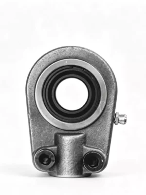
UCFB / UCFA flange bracket and adjustable flange units for applications where the machine needs a nonstandard flange interface, such as a bracket form or adjustable mounting geometry, while retaining a UC-style insert. Catalog evidence covers the set screw type and series-specific bracket or adjustable flange geometry; confirm the exact size row and operating conditions before ordering.
A correct match is most likely when the machine genuinely needs the machine needs a nonstandard flange interface, such as a bracket form or adjustable mounting geometry, while retaining a UC-style insert. In the supplied catalog, UCFB / UCFA is shown as flange bracket and adjustable flange units with set screw type and series-specific bracket or adjustable flange geometry. For UCFB / UCFA, quotation work moves faster when the source designation, shaft or bore dimension and the controlling mounting measurements are checked before optional seal, grease or housing requests are discussed.
Catalog-derived product drawing / mounting view.
Series
UCFB / UCFA
Shaft Lock
Set screw type
Mounting
Series-specific bracket or adjustable flange geometry
Evidence
Supplied catalog, PDF page 40
Product Role
The assembly is chosen to make shaft support repeatable, especially where access and replacement time matter. For UCFB / UCFA, the shaft connection is set screw type, while the external interface is series-specific bracket or adjustable flange geometry; neither should be substituted by appearance alone.
Construction & Fit
The mechanical layout is defined by the way the shaft is retained and by how the unit is fixed to the machine. For UCFB / UCFA, that chain includes set screw type at the shaft and series-specific bracket or adjustable flange geometry at the machine. For UCFB / UCFA, if the bearing/housing arrangement incorporates a spherical seating concept, use that only for limited static mounting tolerance; it is not a remedy for a bent shaft or a distorted frame.
Applications
The catalog family can be considered for custom frames, compact machinery, adjustment mechanisms and retrofit locations where standard square or oval flanges do not match the structure. A drawing match for UCFB / UCFA is only part of the decision; contamination, washdown and available service space can change the preferred specification.
Engineering Review
UCFB and UCFA specialty flange forms are useful when the mounting face does not follow the common square or oval pattern. Their bolt arrangement, bracket geometry or adjustable flange features become the identifying details. When the old part is unknown, make a simple sketch showing hole centers, shaft center and housing outline. This is usually more reliable than trying to identify the unit from a photograph taken at an angle.
Pay attention to how the specialty flange reacts load into the surrounding plate or bracket. A substitute with a convenient bolt pattern may shift that load path or interfere with nearby structure. If the machine mounting was fabricated around the original unit, preserve those fixed dimensions and ask for a match to the cataloged form before considering an alternative housing family.
Specialty flange identification benefits from a paper or digital bolt-pattern template. Record hole centers and shaft center on the same reference rather than measuring each distance independently. This reduces accumulated error when the pattern is asymmetric or adjustable. Add a side view showing housing projection and nearby brackets. Together, these views provide a much stronger interchange record than a product photo without scale.
For an asymmetric or adjustable flange, include one diagonal measurement in addition to normal horizontal and vertical hole spacing. The diagonal provides a quick check against transcription error and helps confirm orientation. This is especially useful when a specialty housing can be rotated into more than one apparent position but only one aligns the shaft correctly.
Technical Specifications
Parameter
Specification / Selection Note
Product form
Flange bracket and adjustable flange units
Catalog series
UCFB / UCFA
Shaft locking
Set screw type
Machine mounting
Series-specific bracket or adjustable flange geometry
Material confirmation
Confirm the exact material grade for UCFB / UCFA on the quotation or current drawing; this page does not infer grade from appearance
Seal / lubrication review
Check the selected UCFB / UCFA designation together with speed, contamination and cleaning conditions
Technical source
Supplied bearing catalog, PDF page 40
Catalog specification and dimensional reference. Confirm the exact row before ordering.
Dimensional Data
The UCFB / UCFA data shown here is intentionally concise. The UCFB / UCFA source-page crop in the gallery contains the complete dimensional layout, so check it whenever an unlisted dimension controls the machine fit.
Catalog Series
Shaft Lock / Interface
Unit Form
Mounting Geometry
Source
UCFB
Set screw type
Flange bracket unit
Bracket geometry
PDF page 40
UCFA
Set screw type
Adjustable flange unit
Adjustable flange geometry
PDF page 40
Selection Notes
A dependable interchange check follows the dimensional chain shown in the catalog. For UCFB / UCFA, record shaft or bore size, series-specific bracket or adjustable flange geometry, and the clearances needed for set screw type. For UCFB / UCFA, include quantity after identification is clear; repeating the same wrong interface across several units only multiplies rework.
Mounting & Integration
Use the drawing as the mounting template, verify clearance through the full adjustment range, align the shaft at the intended working position, and then tighten both housing and insert locks. The main installation hazard for UCFB / UCFA is that specialty housings are easy to confuse from photographs; hole spacing, flange angle and centerline position must come from the drawing. Before startup, inspect UCFB / UCFA from both sides for trapped seals, contact marks or hardware that could rub once the shaft turns.
Maintenance & Inspection
Mark the original adjusted position before service so movement can be detected, and check mounting hardware after any process change that alters belt or chain load. A useful inspection record for UCFB / UCFA includes temperature, contamination tracks, grease behavior and any movement of the locking components.
Customization & RFQ
A UCFB / UCFA request is easier to review when the buyer supplies both the nameplate or stamped code and the dimensions from the installed location. If UCFB / UCFA sees moisture, process debris, chemicals or frequent cleaning, include those facts so the seal and lubrication arrangement can be reviewed. Ever Power Netherlands Branch can then review options for UCFB / UCFA against the supplied application instead of presenting unverified material, seal or grease claims as standard catalog facts.
Cataloged Models
The documented scope on this page includes UCFB flange bracket unit; UCFA adjustable flange unit. Keep the complete UCFB / UCFA suffix or bore variant when matching existing equipment because a shortened code can hide a different locking or dimensional arrangement.
Product FAQ
What should be matched first when replacing UCFB / UCFA?
Treat the fixed machine dimensions as the first filter for UCFB / UCFA: shaft size plus series-specific bracket or adjustable flange geometry. After that, verify the complete UCFB / UCFA designation and set screw type against the source drawing before discussing optional features.
Can the locking method be changed to another bearing family?
A different lock can be considered, but it becomes a machine-selection decision rather than a simple UCFB / UCFA replacement. For a UCFB / UCFA redesign, check shaft condition, axial space, bearing width and tool access before approving the change.
How should sealing and lubrication requirements be specified?
State what reaches the UCFB / UCFA location and how often the machine runs. Include water, abrasive material, cleaning agents and temperature. Sales engineering can then check the available UCFB / UCFA seal and lubrication arrangement against the exact size.
What should be included with the quotation request?
Provide the UCFB / UCFA designation, shaft measurement, mounting sketch, operating speed, load direction, quantity and photos showing surrounding components. For flange bracket and adjustable flange units, the machine-side mounting dimensions are especially important.
Evidence Note
Catalog evidence for UCFB / UCFA is preserved in the gallery as a direct source crop and is the basis for the technical table on this page. The gallery drawing for UCFB / UCFA is a direct catalog crop, not an AI-generated technical illustration. Any application visualization added later for UCFB / UCFA should be treated as illustrative rather than as dimensional evidence.
The technical source for UCFB / UCFA is the supplied catalog, PDF page 40. Customer-level Drive data is not reproduced on the UCFB / UCFA page, while public research is limited to non-proprietary terminology and import guidance.
Ask for a Bearing Review
To check UCFB / UCFA, provide the old part number if available, the controlling dimensions, duty conditions and installation images. Ever Power Netherlands Branch can use that UCFB / UCFA information to narrow the correct catalog variant.
Stainless steel gearboxes are widely used in industrial transmission fields due to their high strength and corrosion resistance. However, in actual use, stainless steel gearboxes may still malfunction due to improper design, installation, lubrication or maintenance....
In modern logistics automation systems, the CC600 Crate Conveyor Chain in Amsterdam plays a crucial role. With the continuous development of warehousing and sorting technologies, enterprises have increasingly higher requirements for the stability, efficiency and...
This article mainly explains and analyzes the structural design characteristics of the sprocket based on its role in the scraper conveyor, thereby leading to the necessity of researching the material and processing technology of the sprocket and the key technical...