Audible noise is evidence to investigate, but fault location depends on whether the sound tracks speed, torque or the machine structure.
Helical Gearbox Noise Diagnosis by Speed and Load
read more


Tri-Ply 209 / 211 Series agricultural disk-harrow bearing units for applications where a disk-harrow bearing unit must match the existing agricultural shaft or axle geometry, including whether the bore is round or square. Catalog evidence covers the round-bore and square-bore configurations shown and agricultural bearing unit geometry per catalog drawing; confirm the exact size row and operating conditions before ordering.
MOQ: 50 pcs. Minimum order value USD 1,500; mixed orders and trial quantities welcome.
The reason to specify this family is not the name alone; it is the need for a disk-harrow bearing unit must match the existing agricultural shaft or axle geometry, including whether the bore is round or square. In the supplied catalog, Tri-Ply 209 / 211 Series is shown as agricultural disk-harrow bearing units with round-bore and square-bore configurations shown and agricultural bearing unit geometry per catalog drawing. For Tri-Ply 209 / 211 Series, quotation work moves faster when the source designation, shaft or bore dimension and the controlling mounting measurements are checked before optional seal, grease or housing requests are discussed.
The support works only when bearing, lock and mounting geometry are considered together instead of as separate catalog items. With Tri-Ply 209 / 211 Series, matching the bore without checking agricultural bearing unit geometry per catalog drawing can produce a part that fits the shaft but not the machine.
A correct build retains the catalog relationship between bore, bearing width and the external support geometry. For Tri-Ply 209 / 211 Series, that chain includes round-bore and square-bore configurations shown at the shaft and agricultural bearing unit geometry per catalog drawing at the machine. Even if the Tri-Ply 209 / 211 Series seat can tolerate modest static angular error, alignment remains a machine requirement rather than a bearing adjustment.
Potential uses include disk harrows and related soil-working implements using the cataloged 209 or 211 unit geometry. For Tri-Ply 209 / 211 Series, dirty or wet service should be stated explicitly so sealing and relubrication can be reviewed instead of assumed from the base code.
The 209 and 211 Tri-ply disk-harrow units are agricultural bearing assemblies where bore form is a decisive identification point. The supplied catalog shows round-bore and square-bore options. Those are not field substitutes: a square axle needs the corresponding interface, while a round shaft requires its own fit. Record the axle shape and across-flat or diameter measurement before ordering, especially when old components are heavily coated with soil or corrosion.
Field duty adds contamination, shock and wash exposure that may not appear in an indoor bearing application. After the first hours of operation, inspect the unit for looseness and seal damage around the disk gang. Keep the gang aligned during assembly so the bearing is not forced sideways by neighboring disks or spacers. If the old unit failed repeatedly, include photos of the full gang rather than only the damaged bearing.
For disk-harrow units, clean only enough soil to expose the bore form, unit code and seal area before photographing the assembly. Heavy wear on one side of a square bore or axle can indicate movement that a new bearing will not correct by itself. Record disk spacing and neighboring hardware while the gang is assembled. Those details help identify whether the replacement problem is bearing selection, axle wear or stack alignment.
For square-bore disk-harrow units, measure across flats and inspect the axle corners separately. Rounded corners can allow movement even when the across-flat dimension seems acceptable. For round bores, look for localized polishing or steps. These axle observations belong in the bearing replacement record because soil-working shock can damage the mating shaft as well as the unit.
| Parameter | Specification / Selection Note |
|---|---|
| Product form | Agricultural disk-harrow bearing units |
| Catalog series | Tri-Ply 209 / 211 Series |
| Shaft locking | Round-bore and square-bore configurations shown |
| Machine mounting | Agricultural bearing unit geometry per catalog drawing |
| Material confirmation | Confirm the exact material grade for Tri-Ply 209 / 211 Series on the quotation or current drawing; this page does not infer grade from appearance |
| Seal / lubrication review | Check the selected Tri-Ply 209 / 211 Series designation together with speed, contamination and cleaning conditions |
| Technical source | Supplied bearing catalog, PDF page 42 |
Use this Tri-Ply 209 / 211 Series table as a quick selection aid, then open the catalog crop in the product gallery before finalizing an interchange. For Tri-Ply 209 / 211 Series, that image preserves the source drawing, symbols and the dimensional columns not repeated in page text.
| Catalog Series | Shaft Lock / Interface | Unit Form | Mounting Geometry | Source |
|---|---|---|---|---|
| 209 Series | Round or square bore | Disk-harrow unit | Agricultural mounting geometry | PDF page 42 |
| 211 Series | Round or square bore | Disk-harrow unit | Agricultural mounting geometry | PDF page 42 |
Before comparing load ratings, confirm that the candidate can actually occupy the same machine envelope. A Tri-Ply 209 / 211 Series replacement needs the actual shaft measurement, the controlling agricultural bearing unit geometry per catalog drawing dimensions and confirmation of round-bore and square-bore configurations shown. Complete the Tri-Ply 209 / 211 Series enquiry with speed, load direction and environment; those inputs keep a dimensional match from being mistaken for complete engineering approval.
Identify the old unit by series and bore form, clean the mounting faces, keep the disk gang aligned through the bearing, and avoid hammering load through the rolling elements during assembly. The main installation hazard for Tri-Ply 209 / 211 Series is that round and square bores are not field substitutes, and agricultural dirt loading makes seal condition just as important as nominal bore size. After the Tri-Ply 209 / 211 Series fasteners are secured, turn the shaft by hand where safe and look for contact with shoulders, guards or neighboring hardware.
Inspect after the first field hours for looseness and seal damage, then base service intervals on contamination and washing exposure rather than calendar time alone. After the first operating period, recheck Tri-Ply 209 / 211 Series for unusual sound, heat and fastener movement, then set the routine interval from actual machine behavior.
When the existing Tri-Ply 209 / 211 Series code is damaged or missing, measure the interface and include photos before dismantling changes the position of spacers or collars. When specifying Tri-Ply 209 / 211 Series, mention contamination and cleaning conditions explicitly; a dry indoor conveyor and an outdoor agricultural drive are not the same duty. Ever Power Netherlands Branch can then review options for Tri-Ply 209 / 211 Series against the supplied application instead of presenting unverified material, seal or grease claims as standard catalog facts.
This page represents 209 Series round-bore and square-bore options; 211 Series round-bore and square-bore options. When ordering Tri-Ply 209 / 211 Series, use the full catalog designation from the selected size row so the bore and mounting details remain traceable.
For Tri-Ply 209 / 211 Series, first confirm the shaft dimension and the machine-side agricultural bearing unit geometry per catalog drawing. Next check the exact series code and its round-bore and square-bore configurations shown. For Tri-Ply 209 / 211 Series, a measured sketch normally resolves more uncertainty than a close-up image of the old unit alone.
Do not assume so. Moving away from the Tri-Ply 209 / 211 Series round-bore and square-bore configurations shown can alter the shaft interface and installation envelope even when the nominal bore is identical. Compare drawings and machine constraints before changing families.
For Tri-Ply 209 / 211 Series, give operating speed and cycle together with dust, moisture, chemicals, washdown and temperature. For Tri-Ply 209 / 211 Series, that duty information is more useful than requesting a generic 'better seal' without describing the exposure.
A complete Tri-Ply 209 / 211 Series enquiry includes the old designation where available, measured shaft or bore, quantity, speed, load direction and clear machine photos. Add the fixed dimensions around the agricultural bearing unit geometry per catalog drawing so interchange can be checked before quotation.
Technical evidence for Tri-Ply 209 / 211 Series comes from the supplied scanned catalog, including its series drawing and model table. The gallery drawing for Tri-Ply 209 / 211 Series is a direct catalog crop, not an AI-generated technical illustration. Any application visualization added later for Tri-Ply 209 / 211 Series should be treated as illustrative rather than as dimensional evidence.
For Tri-Ply 209 / 211 Series, the specification reference used in this import is PDF page 42. Connected Drive findings for Tri-Ply 209 / 211 Series remain internal context; outside web material does not supply competing dimensions or branded performance claims.
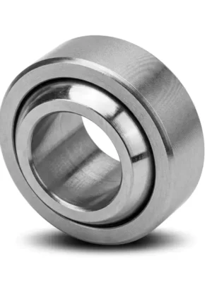
Audible noise is evidence to investigate, but fault location depends on whether the sound tracks speed, torque or the machine structure.
Flexible couplings accommodate limited relative movement, but poor shaft alignment still affects bearings and seals.
Oil observed on a housing may have traveled from a vent, joint or shaft seal; finding the first wet point is essential.