

The commanded VFD frequency changes motor cooling and output torque availability, not just the speed shown on the keypad. VFD nameplate kW does not prove full torque at every frequency. Refer to the VFD geared-motor operation guidance. Compare motor current, torque curve and thermal protection across intended frequencies. Verify winding temperature protection in sustained low-speed use.
Read motor and inverter ratings together
Coordinate acceleration and shock
Save tested parameter revisions
Read motor and inverter ratings together
The VFD sets electrical conditions while the motor design determines continuous mechanical capability; a motor built for fixed-frequency service may need special assessment at slow shaft speed.
VFD nameplate kW does not prove full torque at every frequency; collect motor datasheet and inverter control mode.

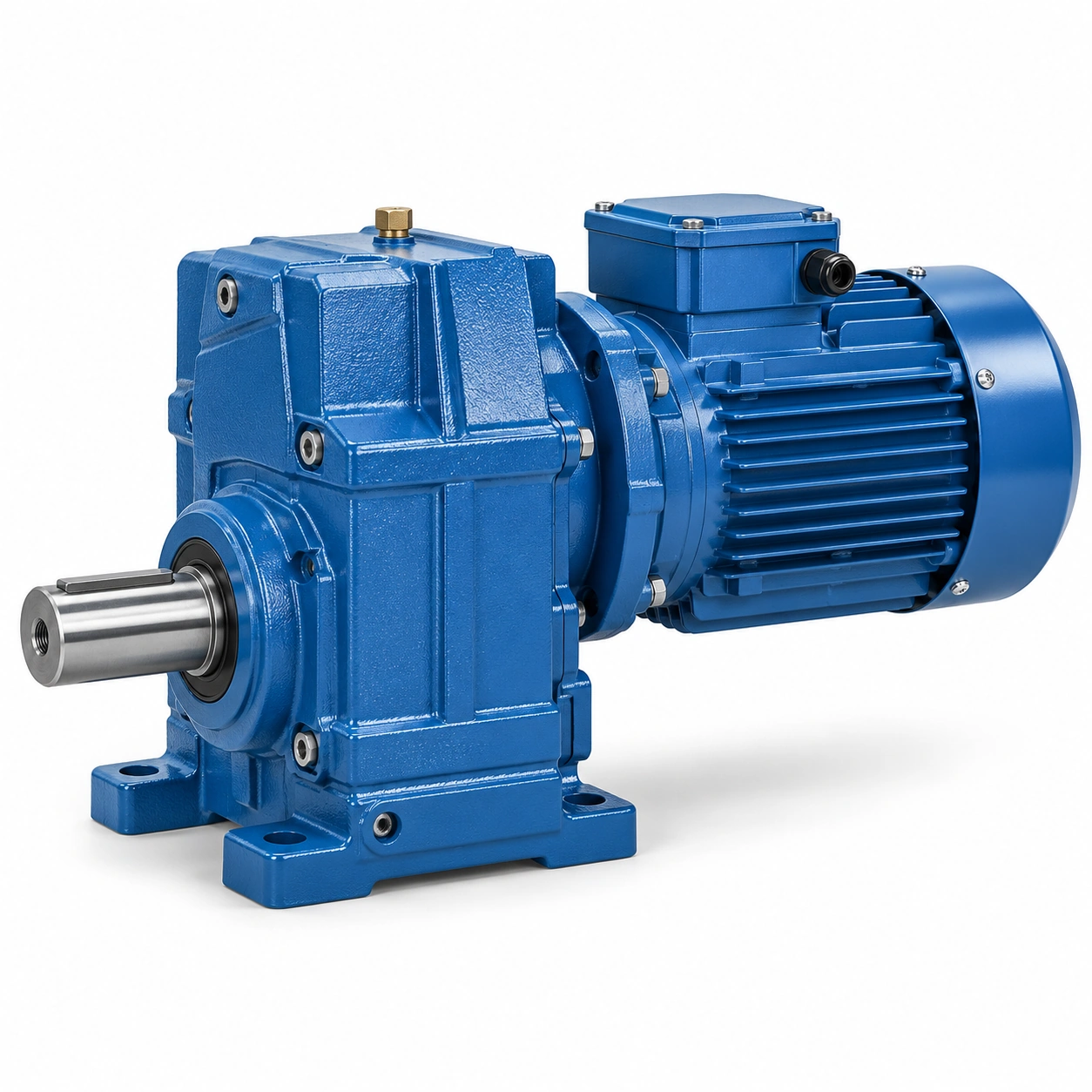
Compare motor current, torque curve and thermal protection across intended frequencies; use an operating envelope authorized by the motor maker; an oversized inverter cannot make an unsuitable motor thermally safe.
Evaluate shaft-driven fan cooling
A fixed shaft-mounted fan moves less air when the motor rotates slowly; full-load operation at reduced frequency can raise winding temperature despite lower rpm.
Assuming low speed always means lower motor heat is misleading; identify time spent near the lowest operating setting.

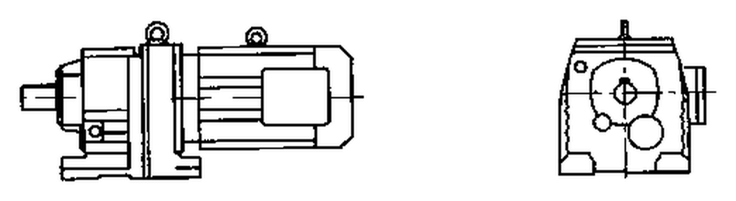
Request forced ventilation or separate cooling approval where required; verify winding temperature protection in sustained low-speed use; the gearbox ratio cannot resolve inadequate motor cooling.
Check torque at low frequency
Torque capability depends on motor type and control strategy at the selected frequency; a loaded conveyor may need substantial torque when creeping slowly.
Reducing speed does not necessarily reduce mechanical demand; map driven torque to motor shaft throughout the speed window.
Use current limits and actual motor torque curves for the chosen control; approve the slowest loaded mode against continuous motor and gear ratings; a successful no-load jog is not proof of low-speed production capacity.
Set a mechanical overspeed ceiling
Increasing frequency may drive the motor above its rated mechanical speed; gearbox bearings, oil churning and tooth contact have input-speed constraints.
An inverter maximum frequency setting is not a permissible gearbox rpm; compare motor and gearbox allowed speed limits.

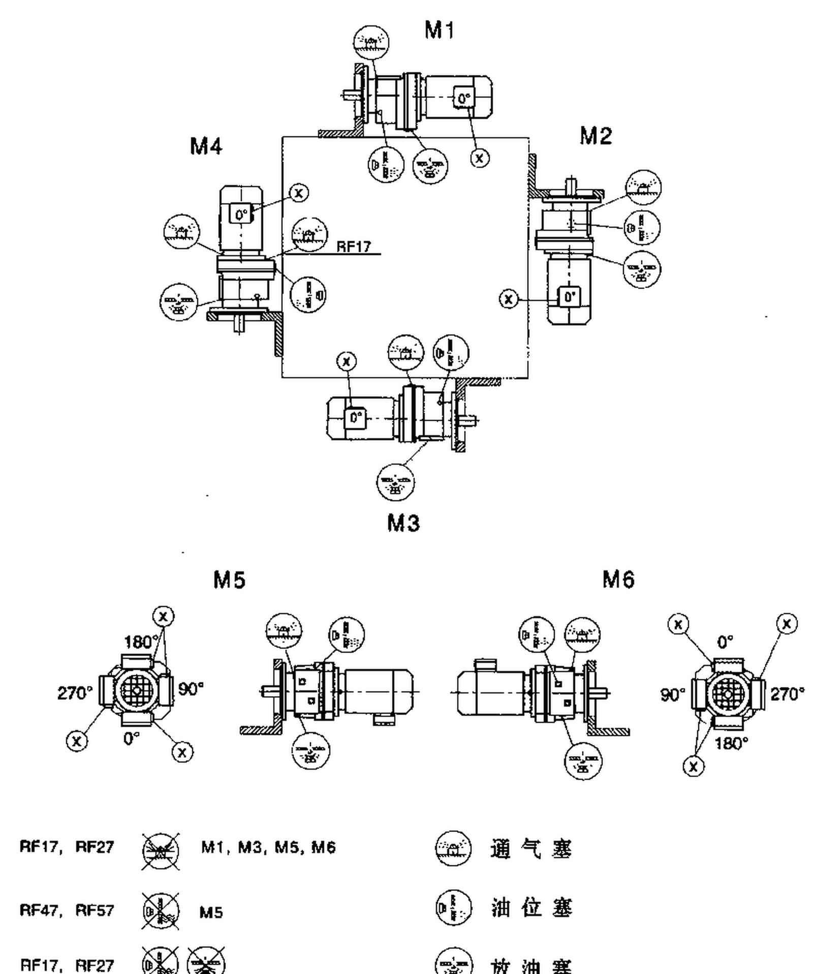
Document speed caps in machine controls and commissioning records; keep all authorized modes below rated mechanical limits; an unreviewed faster recipe can invalidate the original reduction selection.
Coordinate acceleration and shock
VFD ramp parameters change inertial torque applied to the gear train; a short acceleration ramp may increase gear and shaft stress even when final speed is low.
Electrical current limiting cannot guarantee absence of mechanical overload; estimate reflected inertia and load torque during the intended ramp.
Review torque command, current response and load disturbances; accept ramp settings that stay within motor and reducer transient capacity; changes to drive parameters can alter gearbox duty after handover.
A short acceleration ramp may increase gear and shaft stress even when final speed is low. Electrical current limiting cannot guarantee absence of mechanical overload. Examine the VFD geared-motor operation layout example. Review torque command, current response and load disturbances. Accept ramp settings that stay within motor and reducer transient capacity.
Control braking and coastdown
Electrical braking may transmit negative torque through the reduction train; a motor-driven machine can need both controlled coastdown and independent mechanical holding.
Ignoring brake energy and reverse loading can create a stopping hazard; define stop types and required deceleration under load.


Check resistor, regenerative drive and mechanical brake compatibility; validate the entire stop sequence with the machine integrator; an electrical stop command should not be confused with a safety-rated holding device.
Check resonant speed bands
Variable-speed operation can excite frame resonances that fixed-speed machines never encounter; a conveyor might vibrate strongly at one intermediate frequency.
Briefly passing through a resonance does not prove sustained operation there is safe; sweep the operating range under controlled conditions with guards installed.

Record vibration trends against frequency and process load; exclude damaging continuous bands where testing justifies it; a well-sized gearbox can still operate inside an unsuitable machine resonance.
Save tested parameter revisions
A future software upload can modify current limit, ramp and maximum rpm; maintenance may unknowingly change gearbox mechanical duty through a controller setting.
Unversioned VFD settings make reliability incidents hard to reconstruct; export the commissioned parameter list and record approval date.
Tie the accepted drive settings to each machine operating recipe; review parameter changes for mechanical effects before approval; speed-control governance is part of drivetrain maintenance.
Illustrative engineering scenario: An industrial helical gearmotor controlled at reduced motor frequency
Imagine a packaging line whose motor-driven conveyor normally runs at full production speed but sometimes creeps at very low frequency while operators inspect material tracking. The installer assumes that lowering the VFD output frequency will reduce mechanical stress because the machine is turning more slowly. That assumption is incomplete. The conveyor may still require substantial tangential force, and a shaft-mounted motor fan may move much less cooling air at the slow commanded speed. The engineer checks the motor maker continuous torque-versus-speed curve, inverter control mode and available winding protection rather than inferring low-speed suitability from the VFD kW label.
The machine must also make rapid format changes. A new control recipe uses a steeper acceleration ramp to shorten changeover time. Even though the required top output rpm has not changed, the transient torque needed to accelerate rollers and product has increased. The reduction train, coupling and motor current limits therefore need another review. A current limit can protect one aspect of the electrical drive, but the actual mechanical peak at gear teeth may depend on inertia, control response and the time at which the limit acts. Gearbox input-speed limits must also be checked if the designer proposes a higher maximum frequency.
The commissioning team prepares a matrix of permitted combinations: steady low-speed loaded travel, normal production, transient acceleration, controlled stop and maintenance jog. Each has a documented operating duration and load. Motor temperature, output speed, VFD current and any problematic vibration bands are observed at safe representative conditions. The final parameter file is backed up and tied to the machine drawing revision. Later programming changes are compared with this approved envelope. This approach prevents a simple software adjustment from quietly changing the mechanical duty for which the gearbox was originally selected.
A common handover mistake is to record only nominal output speed while leaving the inverter parameter list undocumented. Months later, a technician may increase the frequency limit to solve a throughput issue, unintentionally exceeding the mechanical operating envelope. Capturing the exact parameter revision, approved maximum input rpm and low-speed motor thermal condition makes the limit visible. These are not administrative details: they preserve the connection between the selected gearbox, the motor and the operating process.
The motor and inverter should also be identified by their full model codes, because similarly rated motors can have different cooling arrangements or maximum speeds. Current-limiting parameters are recorded beside their mechanical implications. If a controller replacement changes the control algorithm, commissioning should verify relevant torque and temperature behavior instead of assuming that transferring the numerical setpoints gives an identical mechanical result.
Five-stage review for an industrial helical gearmotor controlled at reduced motor frequency
-
Read motor and inverter ratings togetherCollect motor datasheet and inverter control mode. Use an operating envelope authorized by the motor maker.
-
Evaluate shaft-driven fan coolingRequest forced ventilation or separate cooling approval where required. The gearbox ratio cannot resolve inadequate motor cooling.
-
Set a mechanical overspeed ceilingCompare motor and gearbox allowed speed limits. Keep all authorized modes below rated mechanical limits.
-
Control braking and coastdownCheck resistor, regenerative drive and mechanical brake compatibility. An electrical stop command should not be confused with a safety-rated holding device.
-
Save tested parameter revisionsExport the commissioned parameter list and record approval date. Review parameter changes for mechanical effects before approval.
Engineering comparison matrix: helical gearmotor low speed vfd operation
| Engineering question | Evidence to collect | Review decision |
|---|---|---|
| Read motor and inverter ratings together | Compare motor current, torque curve and thermal protection across intended frequencies. | Use an operating envelope authorized by the motor maker. |
| Evaluate shaft-driven fan cooling | Request forced ventilation or separate cooling approval where required. | Verify winding temperature protection in sustained low-speed use. |
| Check torque at low frequency | Use current limits and actual motor torque curves for the chosen control. | Approve the slowest loaded mode against continuous motor and gear ratings. |
| Set a mechanical overspeed ceiling | Document speed caps in machine controls and commissioning records. | Keep all authorized modes below rated mechanical limits. |
| Coordinate acceleration and shock | Review torque command, current response and load disturbances. | Accept ramp settings that stay within motor and reducer transient capacity. |
| Control braking and coastdown | Check resistor, regenerative drive and mechanical brake compatibility. | Validate the entire stop sequence with the machine integrator. |
Frequently Asked Questions
Does a VFD guarantee constant torque at all speeds?
What happens if the VFD maximum frequency is increased?
Why do acceleration parameters affect gear reliability?
What should be recorded at VFD commissioning?
What makes a final review credible for an industrial helical gearmotor controlled at reduced motor frequency?
A conveyor might vibrate strongly at one intermediate frequency. When comparing actual mounting geometry, use the VFD geared-motor operation configuration options. Record vibration trends against frequency and process load.
Export the commissioned parameter list and record approval date. For an engineering quotation that records the open conditions, contact the technical team about VFD geared-motor operation. Review parameter changes for mechanical effects before approval.
Engineering sources for VFD and Helical Gearmotor Operation at Low Speed
For the vfd and helical gearmotor operation at low speed workflow, consult these reference documents alongside the actual model installation manual:
- VFD and Helical Gearmotor Operation at Low Speed: ABB, Effects of variable speed drives on motors (analysis).
- VFD and Helical Gearmotor Operation at Low Speed: SEW-EURODRIVE, Basic calculation process (interface review).
- VFD and Helical Gearmotor Operation at Low Speed: SEW-EURODRIVE, Application-specific service factor (acceptance checks).