

Gravity changes the relationship between oil level, bearings and the external shaft forces when a gearbox is rotated. An ambiguous orientation note may invalidate an otherwise correct gearbox quotation. Refer to the vertical gearbox installation guidance. State the machine operating posture, not merely how the gearbox is shipped. Accept only a documented oil or grease supply arrangement.
Consider lubrication of the highest bearing
Calculate external axial thrust
Commission shaft and oil conditions together
Identify the actual shaft attitude
Vertical refers to the installed output shaft and may be confused with a vertical mounting surface; an upward output and a downward output can place bearings at different heights relative to the oil.
An ambiguous orientation note may invalidate an otherwise correct gearbox quotation; show a coordinate view with upward arrows and input-output directions.

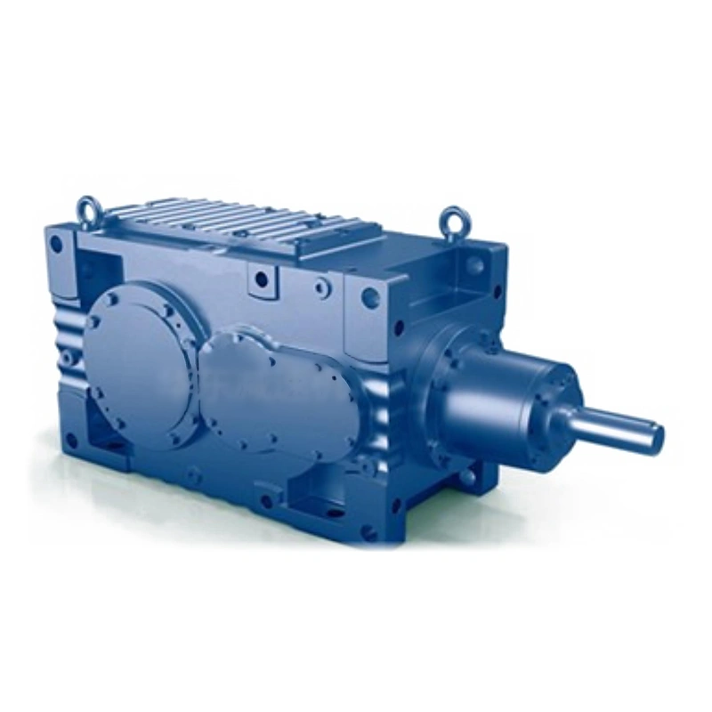
State the machine operating posture, not merely how the gearbox is shipped; confirm the manufacturer mounting-code description matches the sketch; a wrong mounting code can result in incorrect fill instructions.
Consider lubrication of the highest bearing
An upper bearing can sit above the normal splash region in a vertically installed housing; some designs use an approved grease arrangement or internal oil delivery to reach it.
Assuming lifetime lubrication without a diagram can conceal an unprotected bearing; ask for lubrication method of the uppermost bearing at the target shaft speed.

Keep bearing schematic and maker service instructions attached to the model code; accept only a documented oil or grease supply arrangement; insufficient lubrication may first appear as temperature rise or bearing distress.
Locate oil-level reference properly
Oil quantity and level points can be orientation-specific, with plugs serving different roles; a technician might mistake a breather hole for an oil-level reference after rotating the housing.
The wrong level can cause churning or oil starvation even with approved lubricant; mark fill, level and drain points in the real orientation.

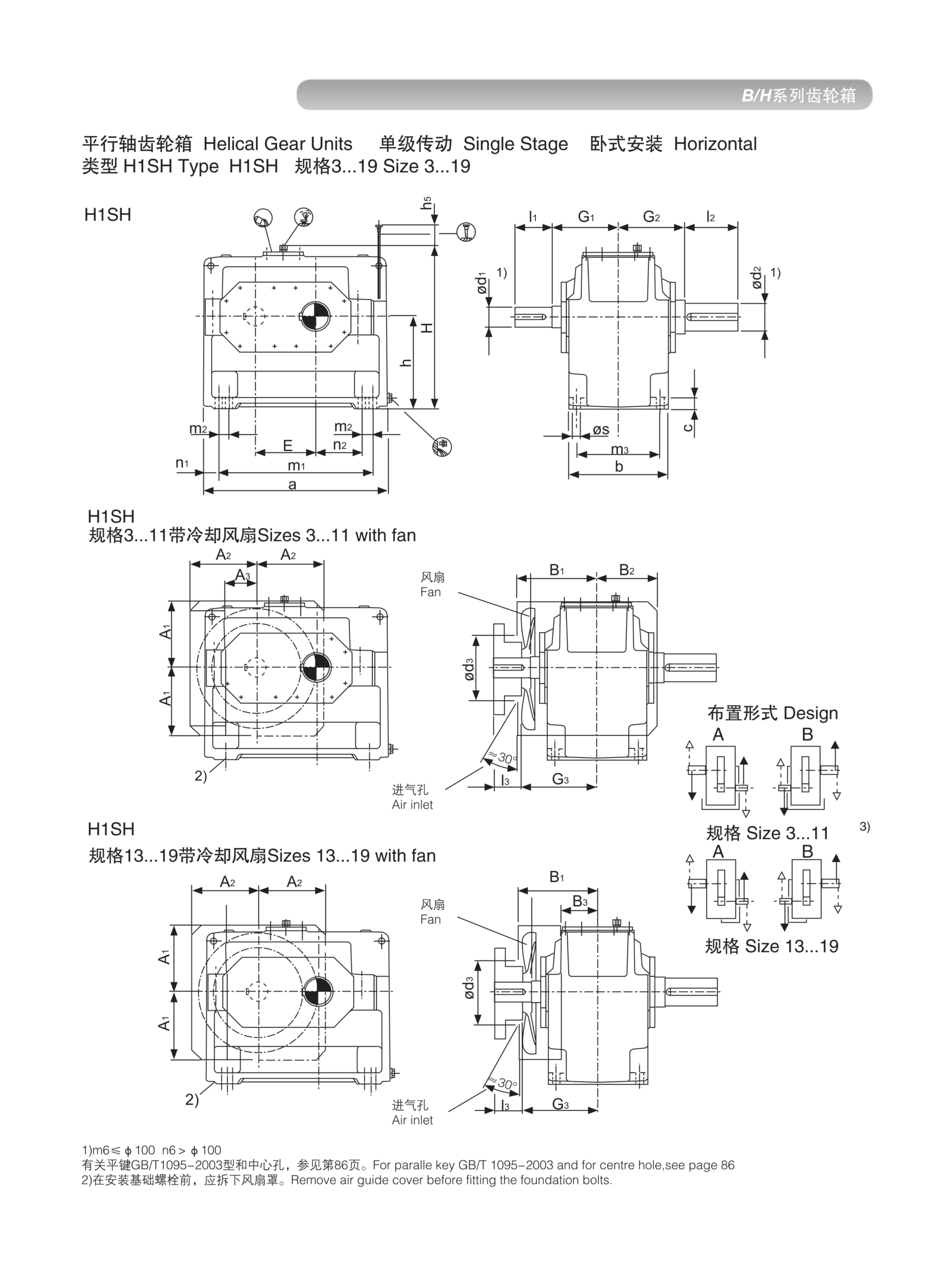
Record fill volume and check procedure provided for that exact position; commission oil fill using the correct source document; the presence of a threaded hole alone does not identify its function.
Position the breather above oil spray
Oil expansion and pressure management need a correctly placed ventilation route; a downward drain or upward shaft arrangement may change where oil splashes internally.
A breather submerged by an unsuitable oil level can cause leaks or pressure issues; check the specified breather orientation and any anti-splash accessory.

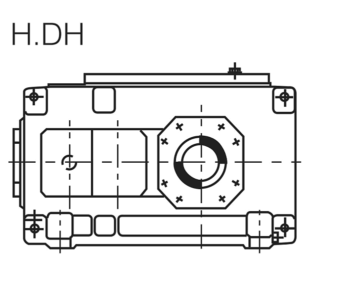
Inspect the access path through surrounding machine guards; approve the ventilation provision for continuous operating conditions; restricted breather access may lead to improvised maintenance later.
Calculate external axial thrust
Gravity, screw thrust or process forces may act along the output shaft in a vertical unit; a downward axial machine load adds a different bearing demand from a purely radial drive.
Gearbox torque capacity gives no allowable axial-load number; prepare the free-body diagram for weight, process thrust and reversals.
Specify force sign, location, rpm and design bearing-life target; obtain permitted Fa at the defined machine configuration; an unverified axial force can shorten output bearing life.
A downward axial machine load adds a different bearing demand from a purely radial drive. Gearbox torque capacity gives no allowable axial-load number. Examine the vertical gearbox installation layout example. Specify force sign, location, rpm and design bearing-life target. Obtain permitted Fa at the defined machine configuration.
Protect upward-facing shaft seals
An exposed upward shaft can collect water or particles at the seal interface; periodic washdown may direct liquid toward a seal lip even if the housing seems sheltered.
Generic protection claims cannot prove this particular installed geometry is water-tight; assess process debris, cleaning direction and shaft guard design.
Request actual shaft seal materials and environmental suitability evidence; use guarding and sealing accepted for the specific environment; a gearbox can be lubricated correctly while external contamination damages its seal.
Check heat in confined vertical housings
Vertical orientation changes which surfaces are exposed to airflow and process heat; a tall gearbox against a vessel wall may reject heat differently from a floor unit.
A normal torque rating does not establish oil temperature at continuous duty; provide ambient temperatures, run time and airflow around the vertical assembly.
Ask for thermal power limits for the selected mounting code; approve operating temperature conditions with manufacturer data; an inadequately cooled top bearing may be missed in a short trial.
Commission shaft and oil conditions together
Rotational direction, load and oil feed should be verified before full production; a vertical drive may appear smooth at no load despite an incorrect bearing lubrication path.
Passing a short free-spin test cannot resolve long-term bearing health; check direction, vent, oil level and shaft forces before progressive loading.

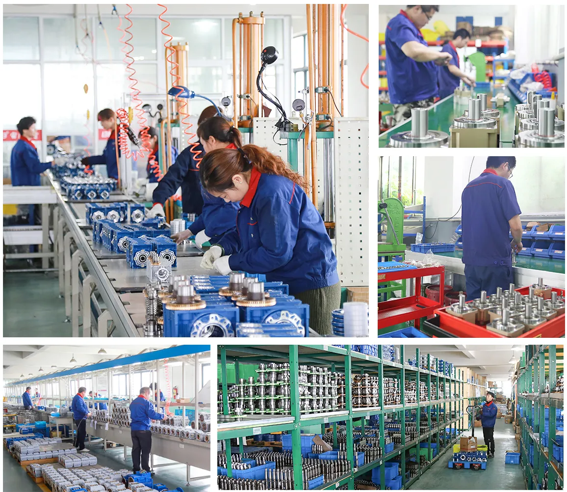
Trend bearing temperature, vibration and leakage over representative operation; retain as-installed measurements and an approved drawing revision; future maintenance depends on knowing the real approved orientation.
Illustrative engineering scenario: An industrial reducer with its output shaft pointing upward or downward
A hypothetical vertical mixer is being assembled above a vessel. The output shaft points downward into the vessel while the motor sits on top. The original horizontal gearbox datasheet shows a familiar fill quantity and a visible level plug. An installer proposes using the same oil quantity because the housing design looks similar. That proposal cannot be accepted without checking the exact mounting version. The highest reducer bearing may now be in a different lubrication region; a drawing of the oil path, fill level and any approved upper-bearing lubrication arrangement must be available from the maker. A grease-lubricated upper bearing must not be described as maintenance-free unless the design documentation actually supports that service statement.
The process shaft carries downward gravitational weight and can also be subjected to upward thrust when the impeller generates lift. These loads belong on the external shaft free-body diagram. The integrator identifies fixed and floating machine bearings, the shaft location relative to the gearbox housing, and the applied force directions. The allowable external axial thrust and bending at the output must be checked using the correct operating speed and bearing-life assumptions. If the process shaft already has a separate thrust bearing, the drawings should make clear which component carries the load so that an accidental duplicate constraint is not introduced.
The team also notes that the vessel is cleaned with warm water. Shaft sealing and condensation deserve review because upward-facing joints may retain moisture. During installation, oil level, breather position and output direction are checked before loading the mixer. The operating test progresses from a controlled spin to representative product mixing, while upper-bearing temperature and leakage are trended. The accepted assembly pack contains a vertical orientation sketch and the exact oil-service instruction. That documentation is more important than a sales image showing a similar reducer on a bench.
Five-stage review for an industrial reducer with its output shaft pointing upward or downward
-
Identify the actual shaft attitudeShow a coordinate view with upward arrows and input-output directions. Confirm the manufacturer mounting-code description matches the sketch.
-
Consider lubrication of the highest bearingKeep bearing schematic and maker service instructions attached to the model code. Insufficient lubrication may first appear as temperature rise or bearing distress.
-
Position the breather above oil sprayCheck the specified breather orientation and any anti-splash accessory. Approve the ventilation provision for continuous operating conditions.
-
Protect upward-facing shaft sealsRequest actual shaft seal materials and environmental suitability evidence. A gearbox can be lubricated correctly while external contamination damages its seal.
-
Commission shaft and oil conditions togetherCheck direction, vent, oil level and shaft forces before progressive loading. Retain as-installed measurements and an approved drawing revision.
Engineering comparison matrix: vertical helical gearbox mounting lubrication
| Engineering question | Evidence to collect | Review decision |
|---|---|---|
| Identify the actual shaft attitude | State the machine operating posture, not merely how the gearbox is shipped. | Confirm the manufacturer mounting-code description matches the sketch. |
| Consider lubrication of the highest bearing | Keep bearing schematic and maker service instructions attached to the model code. | Accept only a documented oil or grease supply arrangement. |
| Locate oil-level reference properly | Record fill volume and check procedure provided for that exact position. | Commission oil fill using the correct source document. |
| Position the breather above oil spray | Inspect the access path through surrounding machine guards. | Approve the ventilation provision for continuous operating conditions. |
| Calculate external axial thrust | Specify force sign, location, rpm and design bearing-life target. | Obtain permitted Fa at the defined machine configuration. |
| Protect upward-facing shaft seals | Request actual shaft seal materials and environmental suitability evidence. | Use guarding and sealing accepted for the specific environment. |
Frequently Asked Questions
Can a conventional helical reducer be rotated into a vertical position?
Why is the top bearing a special concern?
Does gearbox torque tell me how much vertical thrust is allowed?
How can a vertical installation be checked at startup?
What makes a final review credible for an industrial reducer with its output shaft pointing upward or downward?
A tall gearbox against a vessel wall may reject heat differently from a floor unit. When comparing actual mounting geometry, use the vertical gearbox installation configuration options. Ask for thermal power limits for the selected mounting code.
Check direction, vent, oil level and shaft forces before progressive loading. For an engineering quotation that records the open conditions, contact the technical team about vertical gearbox installation. Retain as-installed measurements and an approved drawing revision.
Engineering sources for Vertical Helical Gearbox Mounting — Oil Level and Shaft Support
For the vertical helical gearbox mounting: oil level and shaft support workflow, consult these reference documents alongside the actual model installation manual:
- Vertical Helical Gearbox Mounting: Oil Level and Shaft Support: SEW-EURODRIVE, Change of mounting position (analysis).
- Vertical Helical Gearbox Mounting: Oil Level and Shaft Support: SEW-EURODRIVE, Dimension sheet information (interface review).
- Vertical Helical Gearbox Mounting: Oil Level and Shaft Support: SEW-EURODRIVE, Lubricant tables (acceptance checks).