

Power, shaft speed and efficiency must be placed at the same mechanical boundary before a torque calculation has meaning. Applying electrical and gearbox efficiency factors in the wrong order gives a misleading output. Refer to the motor power to output torque guidance. Write kW at motor shaft and kW at reducer output in separate worksheet columns. Apply the ratio to the intended loaded motor operating point.
Identify whether power is electrical or mechanical
Compare continuous and transient demand
Make the result a procurement comparison
Identify whether power is electrical or mechanical
An electric motor input rating and its useful shaft power describe two different energy boundaries; the reducer receives torque from the motor shaft, not directly from the grid electricity meter.
Applying electrical and gearbox efficiency factors in the wrong order gives a misleading output; read the motor plate and identify the basis of each supplied power figure.


Write kW at motor shaft and kW at reducer output in separate worksheet columns; the calculation must show which efficiency belongs to which conversion; a motor power label is not sufficient evidence of a reducer continuous torque rating.
Use actual loaded input speed
A four-pole induction motor may run below its synchronous speed because of slip; using synchronous rpm in the ratio calculation can shift the predicted output speed.
The machine may require tighter shaft-speed control than a nominal motor designation provides; obtain the rated-load rpm and VFD operating range for the chosen motor.
Record input frequency, actual rpm and whether the speed is nominal or measured; apply the ratio to the intended loaded motor operating point; an input speed error propagates directly into the output rpm calculation.
Calculate the ideal torque reference
The mechanical relation for rotating shafts is torque in N m equal to 9550 times kW divided by rpm; at 5.5 kW and 72.5 rpm, an ideal 100 percent efficient transmission would provide about 724 N m.
Presenting that ideal number as available output torque ignores losses; compute input rpm divided by ratio, then apply the power torque relation.

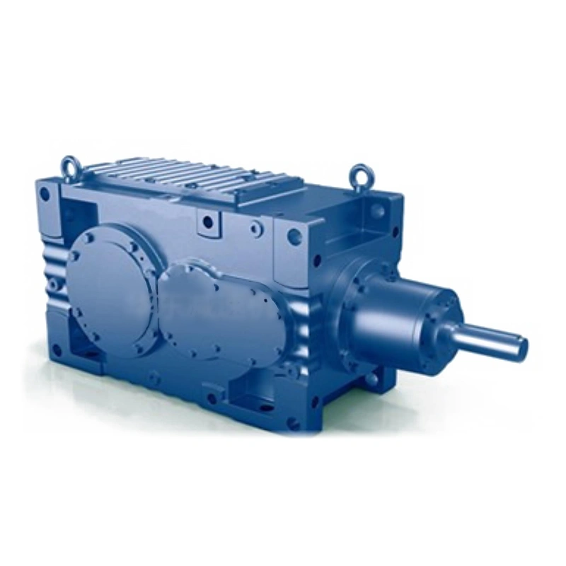
Show power, output rpm and units beside each intermediate result; label the ideal value only as a mathematical reference for the assumed example; the ideal output is a ceiling under those assumed inputs, not a catalogue promise.
Apply actual gearbox loss data
Bearing, seal and tooth-contact losses affect the power delivered downstream; assuming 94 percent gearbox efficiency in the illustrative 5.5 kW case gives about 680 N m at 72.5 rpm.
A generic family efficiency cannot represent every ratio, speed or load point; request rated or measured efficiency for the specific proposed configuration.

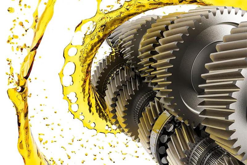
Record lubricant, gear stage count, speed and load associated with the figure; approve a realistic torque estimate only with a justified efficiency assumption; imprecise efficiency can conceal a significant thermal difference.
Compare continuous and transient demand
A machine can exceed its steady operating torque while starting or dealing with a process upset; a motor with a strong short-term overload response may deliver more peak torque than the reducer accepts.
A steady torque calculation alone cannot prove teeth and shafts survive shock; prepare a load-time diagram for startup, normal running and credible peak events.
Specify peak duration and frequency instead of only a maximum number; check continuous and intermittent manufacturer ratings separately; the chosen gearbox can be mechanically undersized even when steady power matches.
A motor with a strong short-term overload response may deliver more peak torque than the reducer accepts. A steady torque calculation alone cannot prove teeth and shafts survive shock. Examine the motor power to output torque layout example. Specify peak duration and frequency instead of only a maximum number. Check continuous and intermittent manufacturer ratings separately.
Add external shaft loads
Output torque transmits rotation but does not specify external radial force capacity; a belt drive or overhung sprocket can apply shaft bending load unrelated to its torque label.
Ignoring bearings can result in a false pass of a motor-to-gearbox calculation; estimate belt or chain resultant force and its offset from the nearest support.

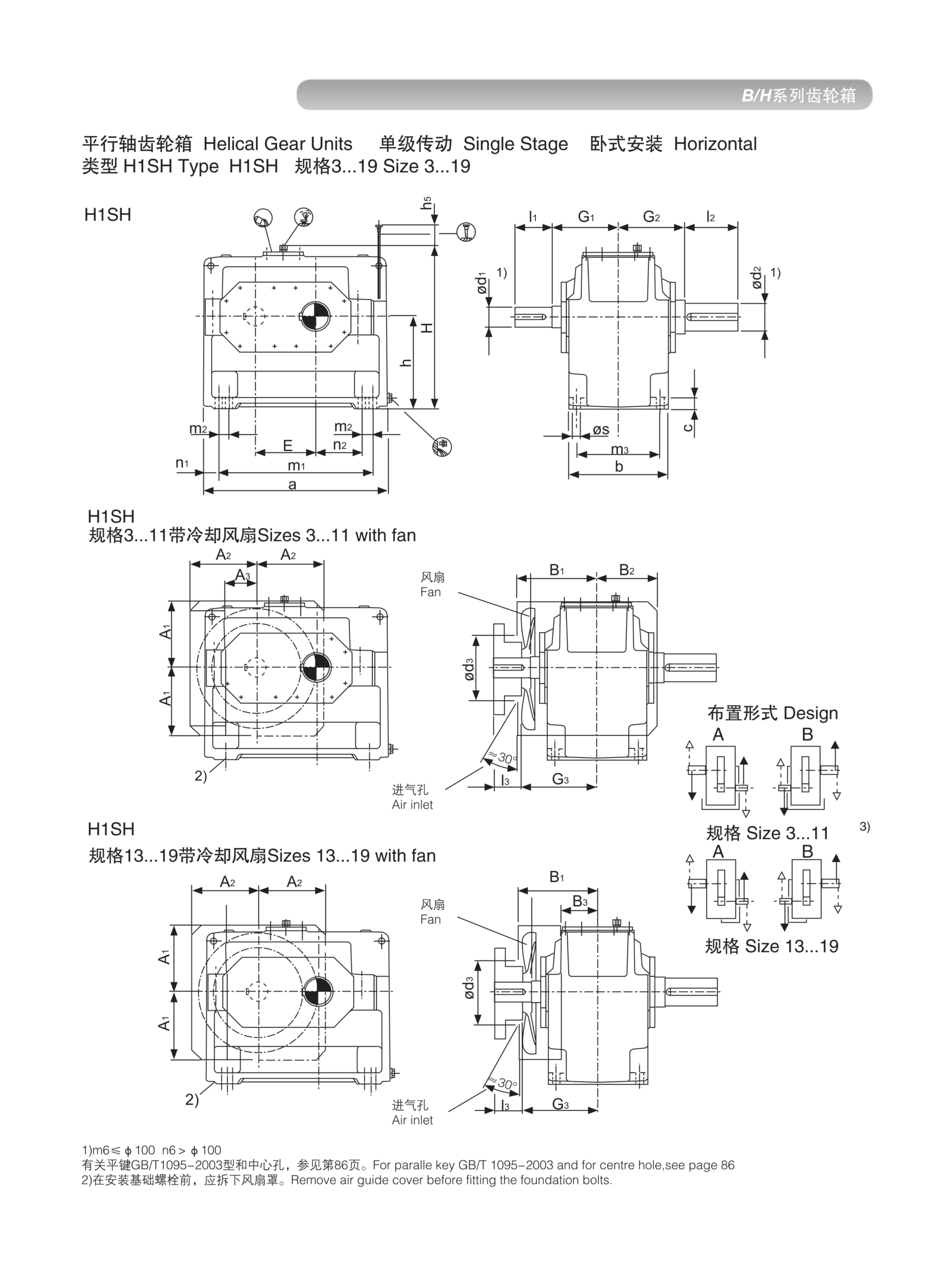
Request allowable Fr and Fa at output rpm, lever arm and required bearing life; include external support where the chosen reducer cannot carry the imposed load; a torque-only approval is incomplete for a protruding output shaft.
Check thermal power under continuous use
Even when mechanical ratings pass, the housing must reject the heat generated by losses; a compact gearbox enclosed behind a guard may experience elevated oil temperature.
Short-duration acceptance tests cannot establish equilibrium temperature; provide duty duration, surrounding air temperature and mounting orientation.
Obtain thermal rating basis and permitted cooling options if necessary; approve sustained operation only within the verified thermal boundary; a well-calculated output torque can still correspond to unacceptable oil temperatures.
Make the result a procurement comparison
Different suppliers can show nominal torque with different duty assumptions and factor conventions; an offer at equal ratio may include a different motor power, output shaft or mounting orientation.
Copying the largest number into a scorecard obscures noncomparable claims; create columns for power basis, input rpm, ratio, efficiency and rated output torque.

Request manufacturer documentation at each proposed model code and mounting position; accept the configuration whose rated envelope covers the documented application; a neat spreadsheet is not useful if the underlying rating definitions differ.
Illustrative engineering scenario: Sizing a motor-driven industrial reducer
Work through a hypothetical 5.5 kW motor with a rated loaded speed of 1,450 rpm. The proposed reducer has a nominal ratio of 20:1, so the calculated nominal output speed is 72.5 rpm. Ignoring losses, the shaft power relation gives T = 9550 x 5.5 / 72.5, or approximately 724 N m. This is an ideal mathematical result, not a continuous capacity rating. If the design exercise assumes a reducer efficiency of 94 percent at that operating point, the estimated useful output power becomes 5.17 kW and the corresponding torque is about 681 N m. Both 94 percent and the example motor information are assumptions chosen for illustration, not published ratings for a particular Ever-Power product.
The calculation now needs two independent checks. First, the gearbox maker must confirm that the selected construction can transmit the required steady torque, along with any short-term acceleration or shock demand. Second, the machine may place force directly onto the output bearings through a belt pulley, sprocket or overhung tool. If the calculated radial force acts outside the bearing, its lever arm must be included in the output bearing assessment. A unit with generous rotational torque capacity may still require another shaft-support arrangement. The manufacturer should state the allowable radial and axial load assumptions for its published figures.
Finally, suppose the equipment operates continuously in a poorly ventilated cabinet. Loss power turns into heat. The preliminary efficiency assumption is not sufficient to establish the thermal capacity of the unit in that cabinet. A proper technical request therefore includes input speed, ambient conditions, duty hours, mounting orientation and permitted cooling provisions. When comparing alternative quotations, keep the ideal arithmetic, estimated delivered power and verified gearbox rating in separate columns. Otherwise a buyer may inadvertently compare a theoretical torque with another supplier's real catalogue limit.
Five-stage review for sizing a motor-driven industrial reducer
-
Identify whether power is electrical or mechanicalRead the motor plate and identify the basis of each supplied power figure. The calculation must show which efficiency belongs to which conversion.
-
Use actual loaded input speedRecord input frequency, actual rpm and whether the speed is nominal or measured. An input speed error propagates directly into the output rpm calculation.
-
Apply actual gearbox loss dataRequest rated or measured efficiency for the specific proposed configuration. Approve a realistic torque estimate only with a justified efficiency assumption.
-
Add external shaft loadsRequest allowable Fr and Fa at output rpm, lever arm and required bearing life. A torque-only approval is incomplete for a protruding output shaft.
-
Make the result a procurement comparisonCreate columns for power basis, input rpm, ratio, efficiency and rated output torque. Accept the configuration whose rated envelope covers the documented application.
Engineering comparison matrix: helical gearbox output torque calculation
| Engineering question | Evidence to collect | Review decision |
|---|---|---|
| Identify whether power is electrical or mechanical | Write kW at motor shaft and kW at reducer output in separate worksheet columns. | The calculation must show which efficiency belongs to which conversion. |
| Use actual loaded input speed | Record input frequency, actual rpm and whether the speed is nominal or measured. | Apply the ratio to the intended loaded motor operating point. |
| Calculate the ideal torque reference | Show power, output rpm and units beside each intermediate result. | Label the ideal value only as a mathematical reference for the assumed example. |
| Apply actual gearbox loss data | Record lubricant, gear stage count, speed and load associated with the figure. | Approve a realistic torque estimate only with a justified efficiency assumption. |
| Compare continuous and transient demand | Specify peak duration and frequency instead of only a maximum number. | Check continuous and intermittent manufacturer ratings separately. |
| Add external shaft loads | Request allowable Fr and Fa at output rpm, lever arm and required bearing life. | Include external support where the chosen reducer cannot carry the imposed load. |
Frequently Asked Questions
What formula converts mechanical kW and rpm into torque?
Where does gearbox efficiency enter the calculation?
Why can output torque be adequate while the reducer is unsuitable?
Is a calculated ideal torque the same as manufacturer rated torque?
What makes a final review credible for sizing a motor-driven industrial reducer?
A compact gearbox enclosed behind a guard may experience elevated oil temperature. When comparing actual mounting geometry, use the motor power to output torque configuration options. Obtain thermal rating basis and permitted cooling options if necessary.
Create columns for power basis, input rpm, ratio, efficiency and rated output torque. For an engineering quotation that records the open conditions, contact the technical team about motor power to output torque. Accept the configuration whose rated envelope covers the documented application.
Engineering sources for How to Estimate Helical Gearbox Output Torque from Motor Power
For the how to estimate helical gearbox output torque from motor power workflow, consult these reference documents alongside the actual model installation manual:
- How to Estimate Helical Gearbox Output Torque from Motor Power: SEW-EURODRIVE, Basic calculation process (analysis).
- How to Estimate Helical Gearbox Output Torque from Motor Power: ABB, Effects of variable speed drives on motors (interface review).
- How to Estimate Helical Gearbox Output Torque from Motor Power: SEW-EURODRIVE, Application-specific service factor (acceptance checks).