

An obsolete model number often conceals shaft, lubrication and mounting conditions that determine replacement success. Matching the visible family code alone can produce a near-fit. Refer to the gearbox retrofit dimensions guidance. Record ratio, direction, motor data and prior maintenance changes. Compare permitted alignment tolerance with replacement geometry.
Measure shaft center height
Map guard and motor interference
Plan commissioning and reversal
Read the full existing nameplate
Model suffixes and serial information can encode shaft direction, accessories and mounting options; a faded number may identify a family but not the complete ordered variant.
Matching the visible family code alone can produce a near-fit; capture full plate photos and any surviving original documents.

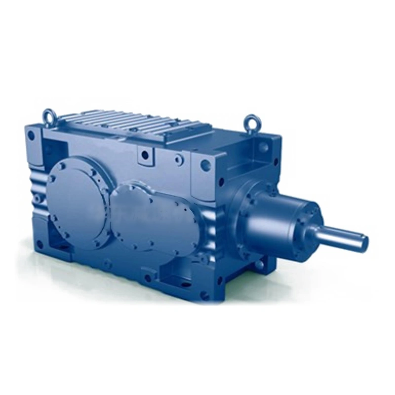
Record ratio, direction, motor data and prior maintenance changes; resolve configuration identity before declaring an equivalent; partial nameplate information belongs in an exceptions log.
Measure shaft center height
The driven machine may require a precise output axis above its foundation; even a modest change in center height can misalign a rigid coupling.
An unmeasured foundation makes the replacement fit uncertain; measure centerline elevation and base position from a stable machine datum.

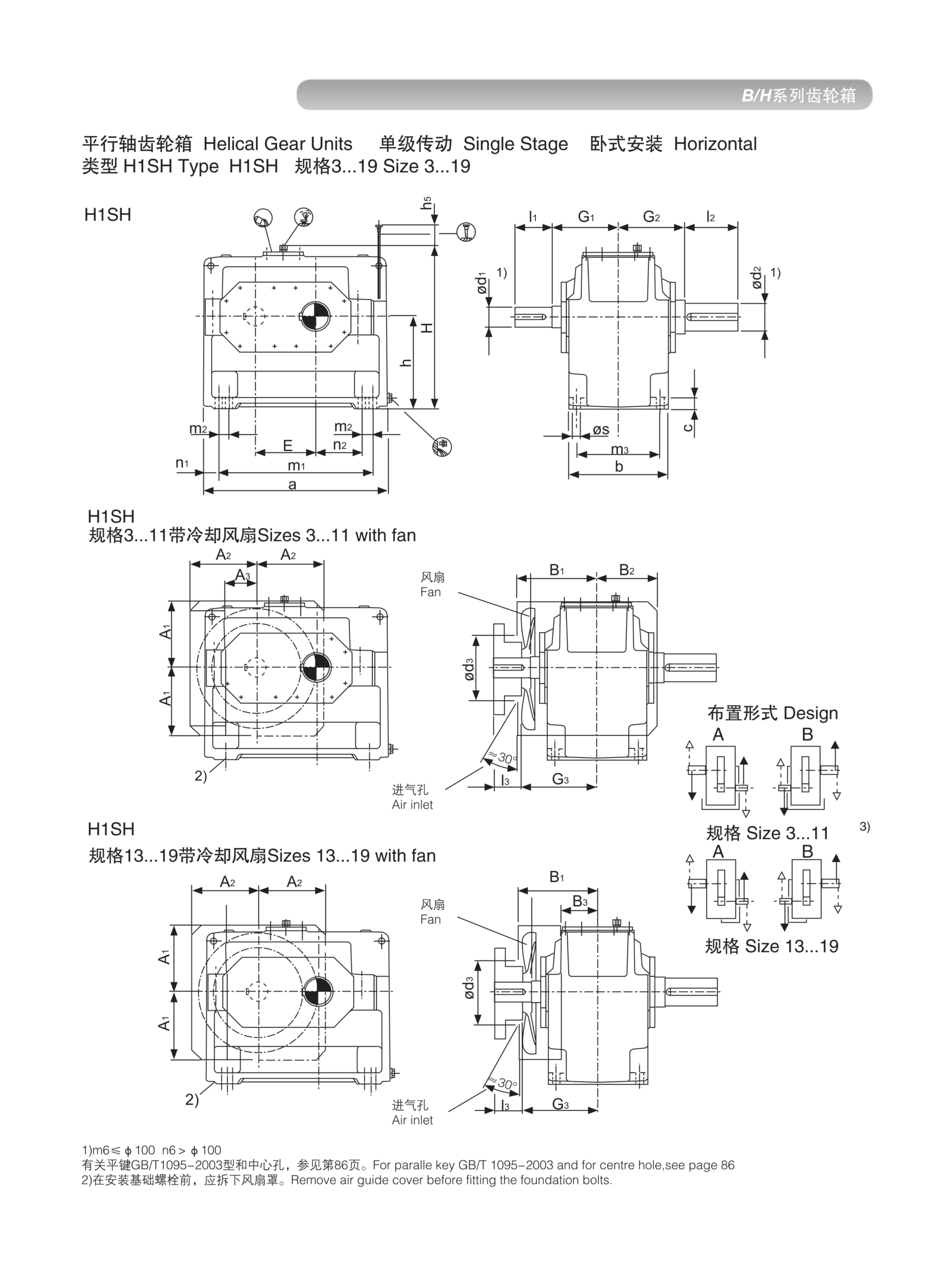
Include support shims and existing mount plate in the dimensioned drawing; compare permitted alignment tolerance with replacement geometry; a similar housing silhouette cannot prove shaft centerline compatibility.
Compare shaft and key details
Output bore, shaft length and keyseat are critical to torque transmission; a replacement shaft may have the right diameter but shorter usable engagement.
A generic dimension chart can omit shoulder and retaining features; measure diameter, fit, key, shoulder and clear shaft projection.
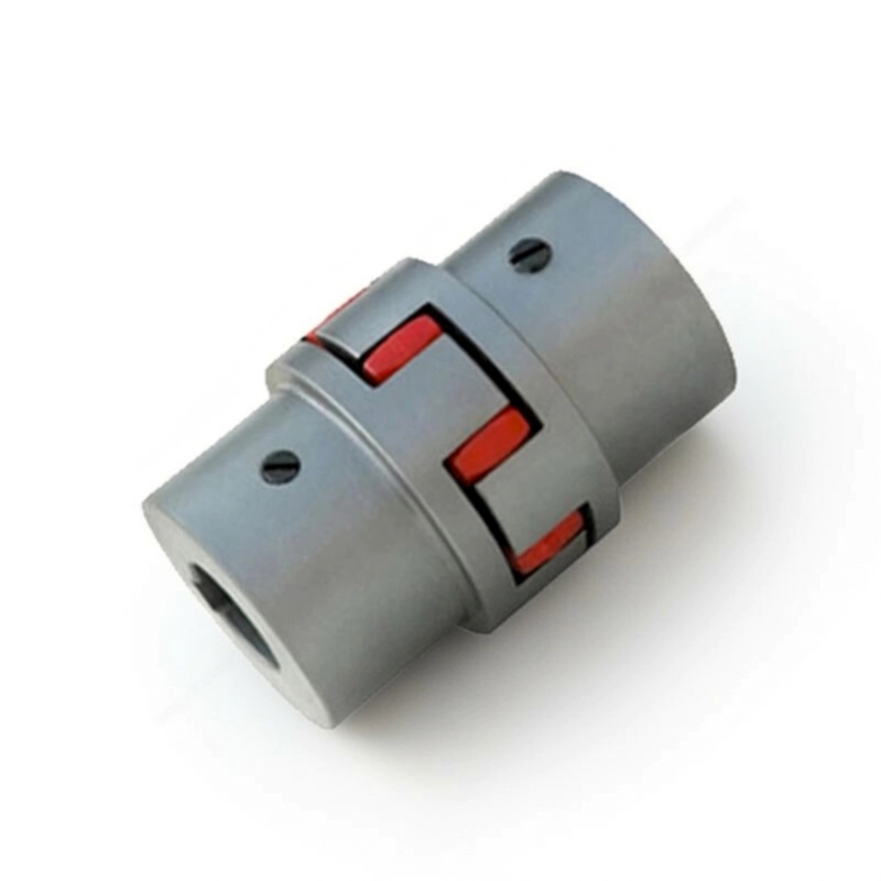
Request exact toleranced output drawing for the proposed gearbox; approve the fully matched mechanical interface; an unverified coupling fit may fail despite equivalent reduction ratio.
Inspect mounting bolt patterns
Foot or flange fit may be constrained by existing cast and welded supports; a new bolt group could interfere with a rib or require base machining.
Field drilling without structural review can weaken the support; measure hole positions, thread sizes and flange register.
Overlay old and new interface drawings on the actual frame; accept structural adaptation only with qualified design review; compatibility includes the supporting machine, not just the gearbox.
Map guard and motor interference
Longer motor or adapter geometry may occupy space reserved for guarding; a few extra centimeters can prevent a track guard or cover from fitting.
Treating overall length as an afterthought can delay restart; model the complete motor gearmotor and coupling envelope.
Check cable direction, fan space and lifting clearance; confirm all guards can be reinstalled without modification or with approved changes; a physically bolted-on unit may still be unsafe or unserviceable.
A few extra centimeters can prevent a track guard or cover from fitting. Treating overall length as an afterthought can delay restart. Examine the gearbox retrofit dimensions layout example. Check cable direction, fan space and lifting clearance. Confirm all guards can be reinstalled without modification or with approved changes.
Validate duty and thermal capacity
Equal nominal ratio does not imply equal continuous torque or permissible bearing force; a replacement selected by size could heat excessively in the same plant duty.
Mechanical similarity is not rating equivalence; obtain existing load, input rpm, starting demand and run hours.
Request rated continuous and peak torque, Fr, Fa and thermal data; choose an alternative whose complete duty envelope is accepted; without ratings a replacement remains a candidate, not an approved equivalent.
Confirm oil position and services
A new housing may use different fill and drain ports at the existing mounting angle; the old oil-service habit may not apply to the new design.
Copying old fill volume is an avoidable lubrication risk; compare mounting-code instructions for both units.

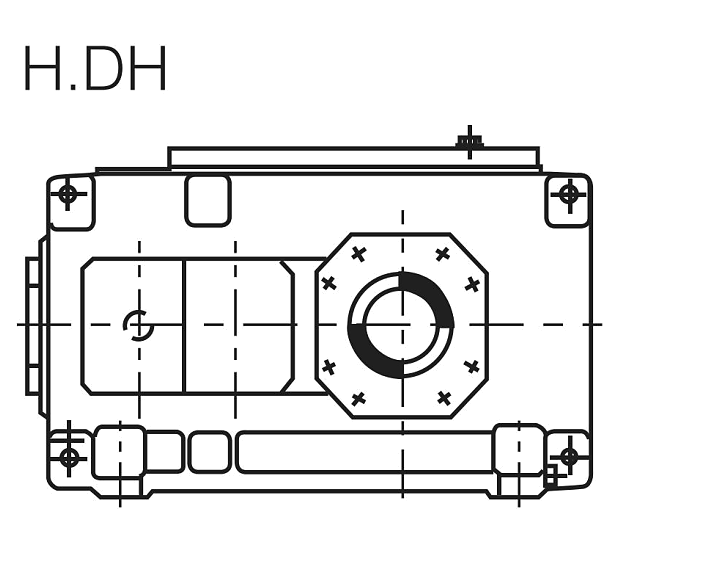
Record approved new lubricant, fill volume and vent position; train maintenance on the new documented service arrangement; a mechanically compatible retrofit can fail quickly from incorrect oil service.
Plan commissioning and reversal
The changeover should preserve shaft rotation, safe stopping and process output; a ratio difference across multiple synchronized drives can create operational conflict.
A no-load rotation test does not prove correct process behavior; check rotation, alignment, guards and all affected control settings.

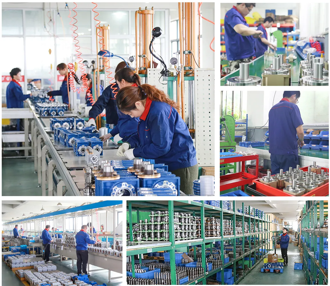
Record full-load current, temperature and vibration after installation; sign off under real operating conditions and machine owner approval; a rushed replacement without a comparison baseline may conceal performance losses.
Illustrative engineering scenario: Replacement of an obsolete industrial reducer on existing machinery
A factory needs to replace an obsolete helical gearbox after a bearing problem. The nameplate gives a model family and nominal ratio, but the original dimensional drawing cannot be located. A bidder suggests a newer reducer with similar motor power. Before ordering, a maintenance technician collects a full set of interface measurements. The machine output shaft centerline is measured from a stable base datum; foot-hole positions, motor clearance, coupling shaft diameter, keyway and usable shaft extension are recorded. A motor fan that adds only a little overall length may still collide with a guard, and an output center height difference may cause severe coupling misalignment. The team therefore compares complete assembled envelopes, not one nominal housing dimension.
The old drive also works next to other synchronized gearboxes. A slightly different ratio could cause speed differences across the machine, even if the new gearbox looks identical. The responsible control engineer documents the operating relationship before approving an alternative. The actual loaded motor speed and output duty are checked so that the replacement is evaluated against continuous torque, starting events and the allowed working speed. If the machine output is driven by a sprocket or pulley, external shaft force and its lever arm are included in the technical enquiry. Nominal torque alone cannot confirm the bearing duty.
The retrofit drawing explicitly shows the proposed motor adapter, flange or foot support, oil positions and the route for servicing the seal. The supplier should return approved lubricant information for the existing mounting attitude. If the new design has a different breather or fill point, the maintenance procedure is updated before the first start. A field compromise such as elongated bolt holes or a shifted coupling shoulder is not accepted without structural and fit review. When a proposed change touches guarding, the machine owner approves a revised arrangement.
After delivery, the installer compares the actual unit with the signed drawing. A controlled first run checks direction and initial mechanical condition. Load is introduced using a preplanned machine procedure, with motor current, noise, vibration and temperature recorded. If the test identifies a deviation, it is logged and resolved rather than hidden by adjusting unrelated parts. A successful retrofit is demonstrated by matched interfaces and approved machine duty, not by the fact that the new gearbox can be bolted onto the old foundation.
The owner may also need a temporary production arrangement while drawings are being confirmed. Such a plan should be reviewed for safety and operating restrictions rather than treated as approval for an unsuitable replacement. Any limited operation must remain within justified conditions and the applicable site process. The final procurement record needs to identify which dimensions were actually measured and which values came from the supplier.
Five-stage review for replacement of an obsolete industrial reducer on existing machinery
-
Read the full existing nameplateCapture full plate photos and any surviving original documents. Resolve configuration identity before declaring an equivalent.
-
Measure shaft center heightInclude support shims and existing mount plate in the dimensioned drawing. A similar housing silhouette cannot prove shaft centerline compatibility.
-
Inspect mounting bolt patternsMeasure hole positions, thread sizes and flange register. Accept structural adaptation only with qualified design review.
-
Validate duty and thermal capacityRequest rated continuous and peak torque, Fr, Fa and thermal data. Without ratings a replacement remains a candidate, not an approved equivalent.
-
Plan commissioning and reversalCheck rotation, alignment, guards and all affected control settings. Sign off under real operating conditions and machine owner approval.
Engineering comparison matrix: helical gearbox retrofit measurements
| Engineering question | Evidence to collect | Review decision |
|---|---|---|
| Read the full existing nameplate | Record ratio, direction, motor data and prior maintenance changes. | Resolve configuration identity before declaring an equivalent. |
| Measure shaft center height | Include support shims and existing mount plate in the dimensioned drawing. | Compare permitted alignment tolerance with replacement geometry. |
| Compare shaft and key details | Request exact toleranced output drawing for the proposed gearbox. | Approve the fully matched mechanical interface. |
| Inspect mounting bolt patterns | Overlay old and new interface drawings on the actual frame. | Accept structural adaptation only with qualified design review. |
| Map guard and motor interference | Check cable direction, fan space and lifting clearance. | Confirm all guards can be reinstalled without modification or with approved changes. |
| Validate duty and thermal capacity | Request rated continuous and peak torque, Fr, Fa and thermal data. | Choose an alternative whose complete duty envelope is accepted. |
Frequently Asked Questions
Is the same gearbox ratio enough to confirm retrofit interchangeability?
What measurements are essential before ordering a replacement reducer?
Why can a seemingly suitable gearbox fail the retrofit review?
How should a gearbox changeover be accepted?
What makes a final review credible for replacement of an obsolete industrial reducer on existing machinery?
The old oil-service habit may not apply to the new design. When comparing actual mounting geometry, use the gearbox retrofit dimensions configuration options. Record approved new lubricant, fill volume and vent position.
Check rotation, alignment, guards and all affected control settings. For an engineering quotation that records the open conditions, contact the technical team about gearbox retrofit dimensions. Sign off under real operating conditions and machine owner approval.
Engineering sources for Helical Gearbox Retrofit — Measurements Before Ordering
For the helical gearbox retrofit: measurements before ordering workflow, consult these reference documents alongside the actual model installation manual:
- Helical Gearbox Retrofit: Measurements Before Ordering: SEW-EURODRIVE, Dimension sheet information (analysis).
- Helical Gearbox Retrofit: Measurements Before Ordering: SEW-EURODRIVE, Change of mounting position (interface review).
- Helical Gearbox Retrofit: Measurements Before Ordering: SKF, Bearing App documentation (acceptance checks).