

Flexible couplings accommodate limited relative movement, but poor shaft alignment still affects bearings and seals. Choosing alignment tolerance from the general term flexible is unsafe. Refer to the inline gearbox coupling alignment guidance. Measure hub separation and coupling reference distances on the equipment. Resolve mechanical defects before final shaft alignment.
Identify coupling construction
Separate angular and parallel offset
Confirm after initial operation
Identify coupling construction
Disc, elastomer, jaw and grid couplings use different mechanical elements and allowable misalignment limits; a flexible component may tolerate a small offset but not an arbitrary bent foundation.
Choosing alignment tolerance from the general term flexible is unsafe; read the installed coupling maker instructions and physical identification.

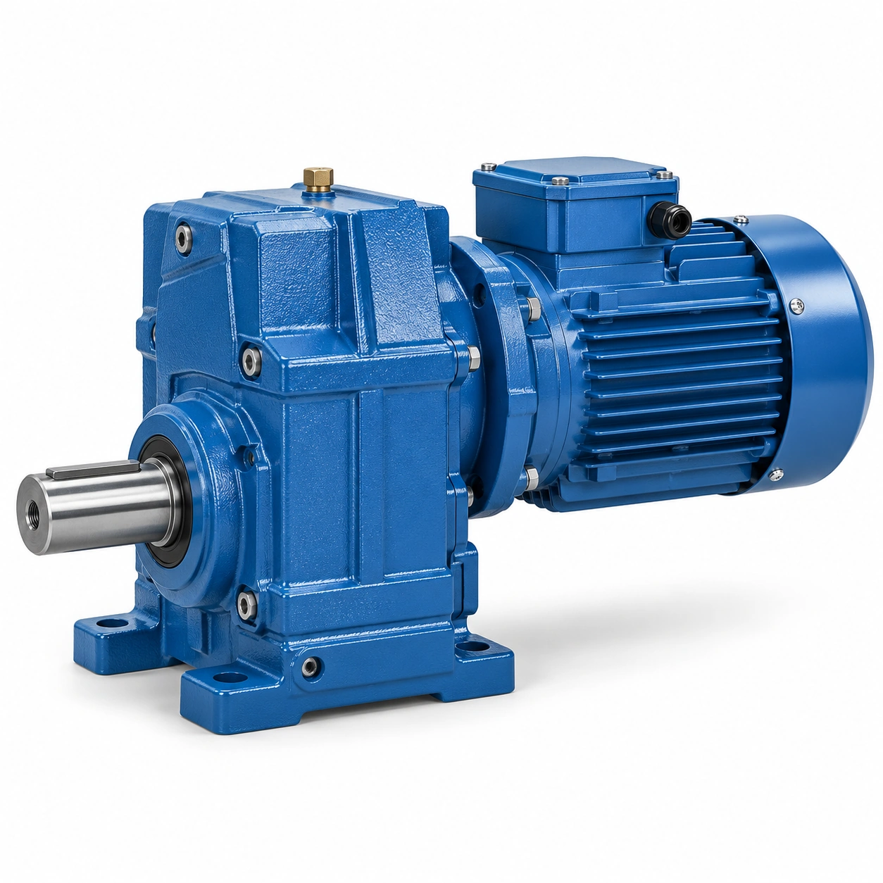
Measure hub separation and coupling reference distances on the equipment; align within that exact construction limit; unverified coupling flexibility can transfer unexpected force into gearbox bearings.
Inspect the machined shaft surfaces
Shaft runout, burrs and loose hubs compromise repeatable measurements; an installer may get a good laser reading on a poorly seated coupling hub.
False reference geometry can create unacceptable running loads; inspect shaft surfaces and verify hubs are fully seated.

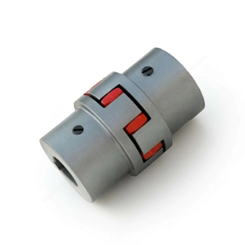
Record runout at a suitable accessible reference under safe conditions; resolve mechanical defects before final shaft alignment; rechecking on defective hub surfaces only repeats the same error.
Correct soft foot before alignment
An uneven mounting base can twist gearbox or motor feet when bolts tighten; a thin shim stack under one corner may change once the machine heats.
Alignment performed before correcting soft foot will not remain stable; check foot gaps and base contact with fastening sequence controlled.

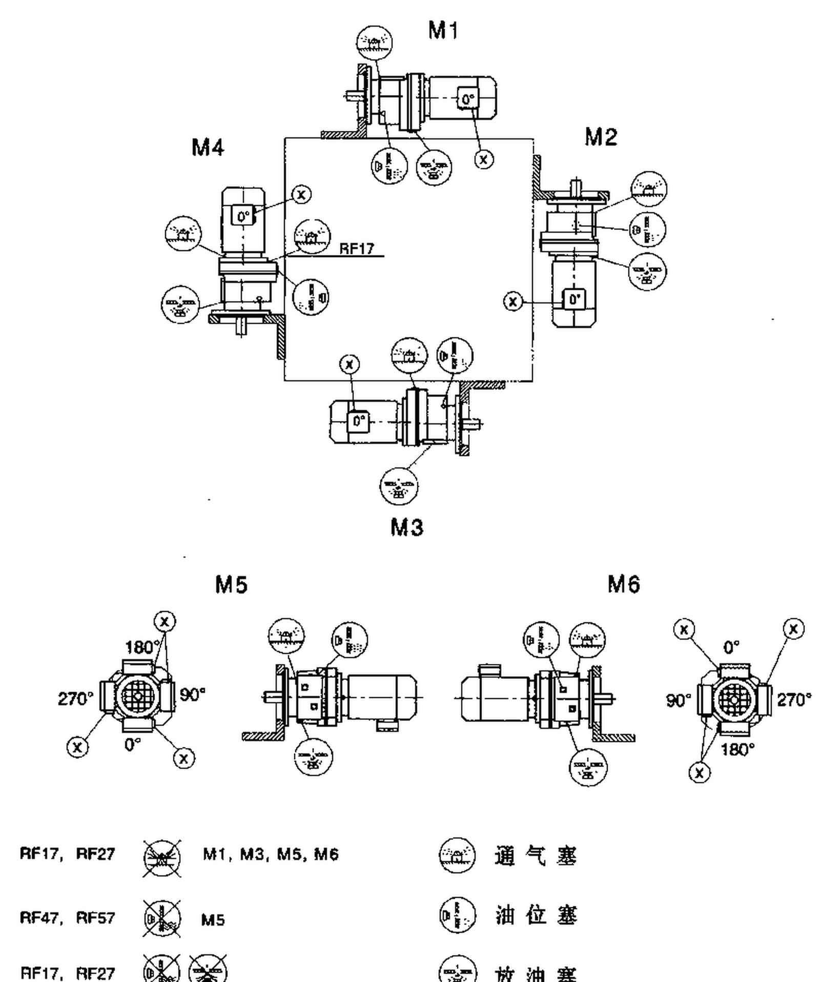
Document shims, bolt torque and support stiffness; begin precision alignment only after supporting geometry is sound; distorted housings create bearing reactions independent of coupling type.
Separate angular and parallel offset
Two shafts can have centerline offset, angular misalignment or both; one dial reading cannot fully describe their relative shaft geometry.
A good-looking coupling guard cannot establish the actual fit; measure relative shaft positions in horizontal and vertical planes.

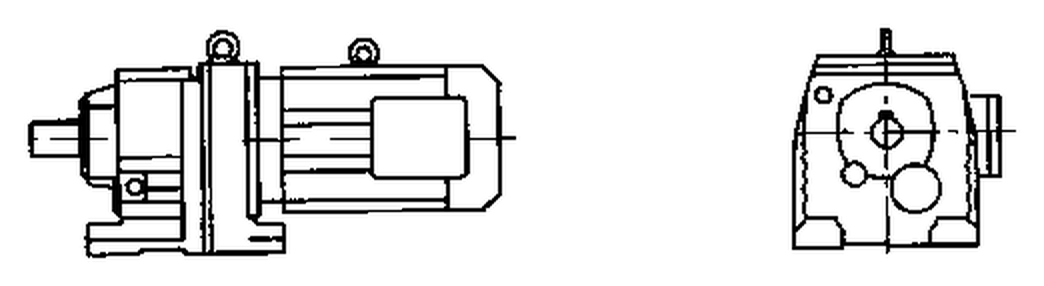
Use laser or dial method appropriate to the chosen coupling; record offset and angular results at their specified reference planes; unresolved shaft angle can wear coupling elements and related bearings.
Predict thermal movement
Machine base, motor and driven shaft can grow by different amounts under operating heat; a cold-aligned pair may shift once the gearbox reaches normal oil temperature.
Reusing a cold alignment target without thermal consideration can be misleading; request equipment-specific hot alignment recommendations.
Record operating temperatures and support heights at the actual plant; apply approved cold offsets where required; thermal assumptions should be validated with operating measurements.
A cold-aligned pair may shift once the gearbox reaches normal oil temperature. Reusing a cold alignment target without thermal consideration can be misleading. Examine the inline gearbox coupling alignment layout example. Record operating temperatures and support heights at the actual plant. Apply approved cold offsets where required.
Account for external piping and belt forces
A driven machine connected to piping or other equipment may move when external loads are applied; a pump inlet strain or a tensioned belt can invalidate an earlier shaft alignment.
Aligning a mechanically unloaded machine can give a false pass; set intended pipe supports or belt tensions before the final check.
Record any residual displacement when process connections are completed; accept the alignment in the actual installed load state; removing the cause of an external load is better than forcing a coupling to absorb it.
Confirm after initial operation
Loaded running can reveal vibration or temperature changes not visible at installation; fastener relaxation or base settlement may shift the shaft positions.
A successful no-load trial alone is not the end of commissioning; record gearbox and driven-machine vibration at defined production conditions.
Recheck fastener condition and alignment after a suitable warm run; close deviations against the machine-approved limit; missing follow-up data weakens the record of installation quality.
Plan future coupling replacement
A replacement coupling can differ in hub position, spacer length or permitted movement; a maintenance crew might install an approximate spare with a different operating envelope.
Compatibility based on shaft diameter alone is incomplete; record exact coupling part and required hub positions.

Save alignment report, photographs and replacement procedure; fit spare parts only against the accepted assembly specification; an unrecorded coupling change can introduce an entirely new failure source.
Illustrative engineering scenario: An inline gearbox connected by a flexible coupling to process equipment
During installation of an inline gearmotor, a technician uses a laser alignment device and obtains a reading that appears comfortably inside the coupling tolerance. A second technician notices that one motor foot has a visible gap from the foundation plate before the fasteners are tightened. When the base bolts are brought to the desired preload, the motor housing twists slightly and the shaft alignment changes. This is a soft-foot problem: the support geometry must be corrected before the alignment numbers can be accepted. The repair does not consist of repeatedly adjusting the coupling until it compensates for a distorted base. A suitable shim plan and corrected foot contact are documented first.
The team then checks the actual flexible coupling assembly. The allowable angular and parallel misalignment are taken from the chosen coupling instructions, not from a generic belief that all flexible couplings can accommodate several millimeters. Hub condition and shaft runout are inspected, while the spacer length and measurement reference planes are recorded. A hot process machine may have a different vertical or horizontal expansion from the gearmotor support. That possibility is considered before the final cold offset is selected. If the OEM requires a thermal compensation target, the team writes it into the procedure with its reason and source.
After the coupling is installed and the pipe supports or belt tension have been applied, alignment is checked again. The first loaded run produces a measured motor and reducer bearing vibration baseline, together with temperatures and process condition. Suppose vibration increases strongly at one load after the changeover. Rather than disassembling the reducer, maintenance first checks whether the coupling hub shifted, the foundation bolts relaxed or external piping strained the driven equipment. This sequence separates installation-induced load from a true gearbox defect. The final job report contains both as-left cold alignment and subsequent loaded observations, making the result reproducible if the machine is moved or serviced in the future.
The same alignment file can guide future work when the machine experiences a bearing replacement. Rather than trying to recreate an undocumented target from memory, technicians use the original hub spacing, base-shim map and approved cold offset. Any replacement coupling is checked against its own permissible misalignment data. If the replacement introduces a different stiffness or spacer, the drivetrain review is reopened. This is a small documentation task with a large effect on repeatable maintenance quality.
A thermal growth review benefits from identifying the physical location of the machine bearings and which component is expected to move when heated. The cold alignment target should be based on the equipment instructions and a defensible growth estimate, not an arbitrary offset. After an initial loaded run, recheck the recorded condition using the approved procedure. This helps ensure that thermal movement has not left the flexible coupling working near its limit.
Five-stage review for an inline gearbox connected by a flexible coupling to process equipment
-
Identify coupling constructionRead the installed coupling maker instructions and physical identification. Align within that exact construction limit.
-
Inspect the machined shaft surfacesRecord runout at a suitable accessible reference under safe conditions. Rechecking on defective hub surfaces only repeats the same error.
-
Separate angular and parallel offsetMeasure relative shaft positions in horizontal and vertical planes. Record offset and angular results at their specified reference planes.
-
Account for external piping and belt forcesRecord any residual displacement when process connections are completed. Removing the cause of an external load is better than forcing a coupling to absorb it.
-
Plan future coupling replacementRecord exact coupling part and required hub positions. Fit spare parts only against the accepted assembly specification.
Engineering comparison matrix: inline helical gearbox coupling alignment
| Engineering question | Evidence to collect | Review decision |
|---|---|---|
| Identify coupling construction | Measure hub separation and coupling reference distances on the equipment. | Align within that exact construction limit. |
| Inspect the machined shaft surfaces | Record runout at a suitable accessible reference under safe conditions. | Resolve mechanical defects before final shaft alignment. |
| Correct soft foot before alignment | Document shims, bolt torque and support stiffness. | Begin precision alignment only after supporting geometry is sound. |
| Separate angular and parallel offset | Use laser or dial method appropriate to the chosen coupling. | Record offset and angular results at their specified reference planes. |
| Predict thermal movement | Record operating temperatures and support heights at the actual plant. | Apply approved cold offsets where required. |
| Account for external piping and belt forces | Record any residual displacement when process connections are completed. | Accept the alignment in the actual installed load state. |
Frequently Asked Questions
Does a flexible coupling eliminate the need for shaft alignment?
Why might cold alignment not match operating alignment?
Should belt tension or connected piping be applied during alignment checks?
Which alignment measurements should be saved for future maintenance?
What makes a final review credible for an inline gearbox connected by a flexible coupling to process equipment?
Fastener relaxation or base settlement may shift the shaft positions. When comparing actual mounting geometry, use the inline gearbox coupling alignment configuration options. Recheck fastener condition and alignment after a suitable warm run.
Record exact coupling part and required hub positions. For an engineering quotation that records the open conditions, contact the technical team about inline gearbox coupling alignment. Fit spare parts only against the accepted assembly specification.
Engineering sources for Coupling Alignment for Inline Helical Gearbox Installations
For the coupling alignment for inline helical gearbox installations workflow, consult these reference documents alongside the actual model installation manual:
- Coupling Alignment for Inline Helical Gearbox Installations: SKF, Bearing App documentation (analysis).
- Coupling Alignment for Inline Helical Gearbox Installations: SEW-EURODRIVE, Dimension sheet information (interface review).
- Coupling Alignment for Inline Helical Gearbox Installations: SEW-EURODRIVE, Basic calculation process (acceptance checks).