

A ratio has to serve the whole required output-speed range while the motor still produces safe torque and cooling. Selecting ratio from only maximum production speed can make low-speed operation impractical. Refer to the variable-speed gear reduction guidance. Collect tolerances, direction changes and minimum time in each operating band. Evaluate more than one nearby ratio against the full speed window.
Describe the machine speed window
Account for low-speed cooling
Address precision and feedback
Describe the machine speed window
An automated line normally needs a production range and a separate adjustment or jog speed; a filler that must run 20 to 60 rpm at output imposes different requirements from a machine with a fixed 40 rpm target.
Selecting ratio from only maximum production speed can make low-speed operation impractical; specify output rpm for minimum loaded, normal and maximum production conditions.


Collect tolerances, direction changes and minimum time in each operating band; choose candidates that reach all required speeds inside the approved motor range; a nominally correct ratio may be unusable for extended low-rpm operation.
Start with loaded motor rpm
An induction motor changes shaft speed slightly under load and VFD output frequency; a 1450 rpm rated motor requiring 29 rpm output suggests a nominal reduction around fifty to one.
Using 1500 synchronous rpm instead would make the preliminary ratio different; compute loaded input speed divided by the desired output speed.

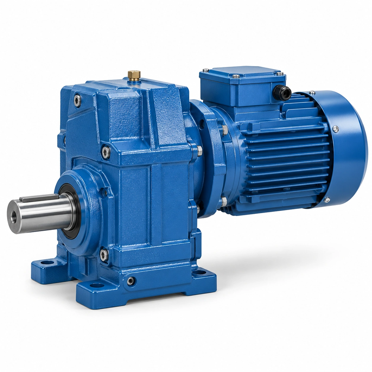
Record assumed slip, rated frequency and available ratio alternatives from actual catalogues; evaluate more than one nearby ratio against the full speed window; exact output speed cannot be guaranteed from ratio and pole count alone.
Check motor torque-speed behavior
The motor and VFD provide an allowable continuous torque envelope rather than constant power everywhere; some applications demand full conveyor force while the motor turns slowly for long periods.
A ratio chosen for speed may ask for more low-speed torque than the drive can deliver; read the inverter and motor characteristic curves for cooling and current limits.

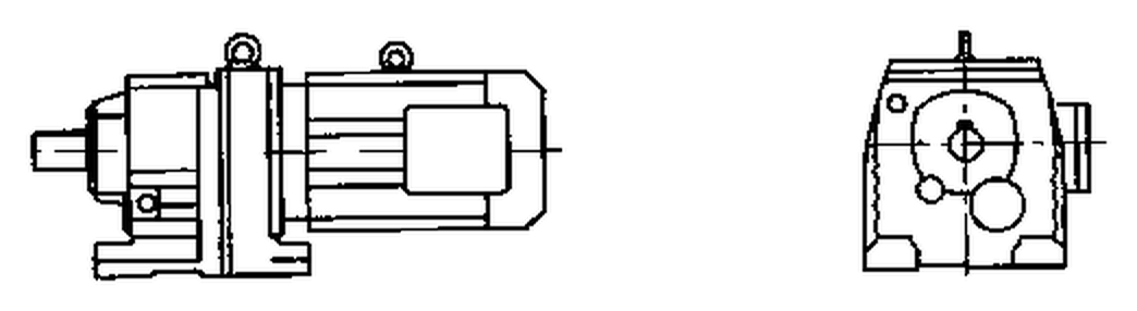
Plot required output torque back to the motor shaft across the intended range; select only operating points supported by continuous motor and reducer ratings; an inverter frequency setpoint does not establish usable mechanical torque.
Account for low-speed cooling
Motors with shaft-driven fans may lose cooling airflow when operated slowly; a long period near a few hertz can heat a loaded motor even when gearbox torque is within limits.
Ignoring the fan limitation can lead to nuisance trips or reduced motor life; check motor maker requirements for forced ventilation or thermal sensors.

Record low-frequency dwell time and surrounding cabinet temperature; approve long low-speed operation only when thermal protection is substantiated; the reducer ratio cannot compensate for inadequate electric motor cooling.
Control the speed ceiling
Increasing VFD frequency raises mechanical shaft speed and may violate motor or bearing limits; an overspeed request can also change splash lubrication and gearbox housing losses.
A motor that spins quickly does not make every gearbox input rpm acceptable; compare maximum motor speed with the reducer specified input limit.
Define a VFD ceiling and mechanical overspeed handling strategy; set operating software and protective limits within maker-approved speeds; an uncontrolled high-speed commissioning sweep can damage the drivetrain.
An overspeed request can also change splash lubrication and gearbox housing losses. A motor that spins quickly does not make every gearbox input rpm acceptable. Examine the variable-speed gear reduction layout example. Define a VFD ceiling and mechanical overspeed handling strategy. Set operating software and protective limits within maker-approved speeds.
Include acceleration time and inertia
Rapid acceleration asks the motor to move rotating mass as well as overcome process load; a high-inertia roller can require significant transient torque at the start of each changeover.
A steady ratio calculation does not bound peak gear tooth demand; estimate system inertia and desired acceleration in seconds.
Check reflected inertia and motor current during a representative speed ramp; approve acceleration settings using motor, coupling and gearbox transient limits; changing a controller ramp after installation can invalidate the original sizing.
Address precision and feedback
Gear reduction alone does not correct motor slip, control lag or mechanical backlash; a packaging register that requires repeatable stopping may need encoder feedback and control tuning.
A precise nominal ratio is not proof of positional accuracy; state allowable speed error, settling time and reversing accuracy.
Document encoder placement, feedback signal and drive control mode; accept measured output response at representative loads and speeds; a reducer with a suitable ratio may still fail process positioning requirements.
Validate all operating recipes
A production line may operate differently during cleaning, threading, warmup and emergency return; special low-speed modes can become the most demanding thermal case.
Testing only one recipe can overlook the configuration that causes damage; prepare a mode table with speed, load, duration and stopping behavior.

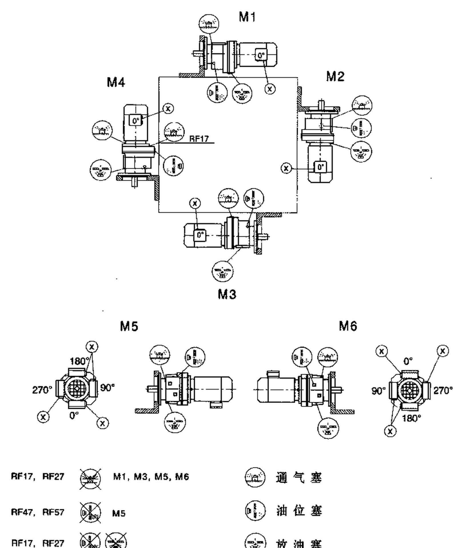
Measure output rpm, drive current and temperature during representative modes; commission the permitted range and preserve the tested control parameter file; future recipe changes should trigger a duty review rather than an undocumented speed change.
Illustrative engineering scenario: A production machine controlled through a variable-frequency drive
A line designer needs a roller to run from approximately 20 to 60 rpm, depending on product format. The proposed motor is rated around 1,450 rpm under normal load and will be controlled by a VFD. A fixed ratio of 50:1 would give roughly 29 rpm at nominal motor speed, but that single point does not prove the full range is viable. At lower commanded frequencies the motor may not provide the same usable continuous torque, especially if it relies on a shaft-driven fan. At higher frequencies there may be input-speed, bearing or lubrication limitations. Candidate ratios should be compared over the complete duty window using actual motor and gear unit curves.
The engineering table includes minimum, normal and maximum roller rpm for each operating recipe, together with product load and ramp time. The motor torque-speed curve is applied at the corresponding shaft frequency, and then the gearbox input limit is checked. A recipe that demands high torque at the slowest setting may need forced motor cooling or a different transmission ratio. Conversely, a configuration selected only for low speed may ask the motor to exceed its approved rotational limit in the fastest recipe. Neither conclusion can be drawn reliably from motor pole count alone.
The machine also stops at an indexed position after each batch. That requirement introduces a feedback question separate from the ratio question. Encoder placement, brake control and backlash behavior affect repeatability. A geared motor that can reach the requested speed may still require sensor or control changes to achieve the required stopping accuracy. The acceptance program should therefore include the output-speed extremes, sustained low-speed full-load operation, transitions between recipes and representative stopping cycles. Preserve the tested VFD parameter set with the approved mechanical selection so later programming adjustments can be reviewed for their effect on the gearbox.
Five-stage review for a production machine controlled through a variable-frequency drive
-
Describe the machine speed windowSpecify output rpm for minimum loaded, normal and maximum production conditions. Choose candidates that reach all required speeds inside the approved motor range.
-
Start with loaded motor rpmRecord assumed slip, rated frequency and available ratio alternatives from actual catalogues. Exact output speed cannot be guaranteed from ratio and pole count alone.
-
Account for low-speed coolingCheck motor maker requirements for forced ventilation or thermal sensors. Approve long low-speed operation only when thermal protection is substantiated.
-
Include acceleration time and inertiaCheck reflected inertia and motor current during a representative speed ramp. Changing a controller ramp after installation can invalidate the original sizing.
-
Validate all operating recipesPrepare a mode table with speed, load, duration and stopping behavior. Commission the permitted range and preserve the tested control parameter file.
Engineering comparison matrix: helical gearbox ratio selection vfd
| Engineering question | Evidence to collect | Review decision |
|---|---|---|
| Describe the machine speed window | Collect tolerances, direction changes and minimum time in each operating band. | Choose candidates that reach all required speeds inside the approved motor range. |
| Start with loaded motor rpm | Record assumed slip, rated frequency and available ratio alternatives from actual catalogues. | Evaluate more than one nearby ratio against the full speed window. |
| Check motor torque-speed behavior | Plot required output torque back to the motor shaft across the intended range. | Select only operating points supported by continuous motor and reducer ratings. |
| Account for low-speed cooling | Record low-frequency dwell time and surrounding cabinet temperature. | Approve long low-speed operation only when thermal protection is substantiated. |
| Control the speed ceiling | Define a VFD ceiling and mechanical overspeed handling strategy. | Set operating software and protective limits within maker-approved speeds. |
| Include acceleration time and inertia | Check reflected inertia and motor current during a representative speed ramp. | Approve acceleration settings using motor, coupling and gearbox transient limits. |
Frequently Asked Questions
How do I determine a preliminary helical gearbox ratio?
Can a motor run at very low frequency with full load?
What else changes when a VFD ramp is shortened?
Does a precise reduction ratio guarantee accurate positioning?
What makes a final review credible for a production machine controlled through a variable-frequency drive?
A packaging register that requires repeatable stopping may need encoder feedback and control tuning. When comparing actual mounting geometry, use the variable-speed gear reduction configuration options. Document encoder placement, feedback signal and drive control mode.
Prepare a mode table with speed, load, duration and stopping behavior. For an engineering quotation that records the open conditions, contact the technical team about variable-speed gear reduction. Commission the permitted range and preserve the tested control parameter file.
Engineering sources for Choosing a Helical Gearbox Ratio for Variable-Speed Machines
For the choosing a helical gearbox ratio for variable-speed machines workflow, consult these reference documents alongside the actual model installation manual:
- Choosing a Helical Gearbox Ratio for Variable-Speed Machines: SEW-EURODRIVE, Basic calculation process (analysis).
- Choosing a Helical Gearbox Ratio for Variable-Speed Machines: ABB, Effects of variable speed drives on motors (interface review).
- Choosing a Helical Gearbox Ratio for Variable-Speed Machines: SEW-EURODRIVE, Application-specific service factor (acceptance checks).