

Coaxial and parallel-shaft reducers place the motor, support and driven output differently in the machine. Ignoring centerlines leads to unnecessary machining changes. Refer to the inline and parallel-shaft comparison guidance. Measure offset distance and available motor length. Verify a workable installed and service configuration.
Draw axis geometry first
Understand structural mounting
Preserve access for service
Draw axis geometry first
Inline drives place input and output near a common axis while parallel units provide offset; machine shaft height may be fixed while motor envelope can move.
Ignoring centerlines leads to unnecessary machining changes; establish machine datums and draw both shaft axes.

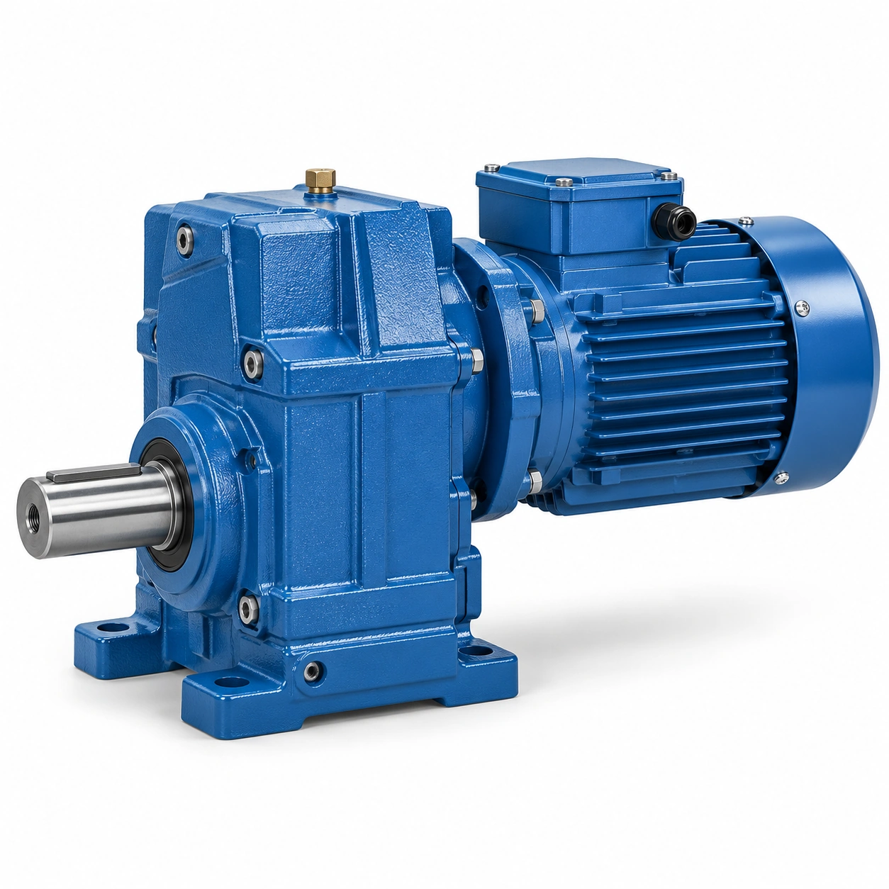
Measure offset distance and available motor length; choose an envelope that clears the process equipment; a catalogue side view cannot replace a machine layout drawing.
Check coaxial coupling access
An inline gearmotor may use a straightforward coupling to the driven machine; a tight rear wall can block motor extraction along its axis.
The apparently simple coaxial choice may complicate maintenance; plan coupling assembly and shaft withdrawal along centerline.

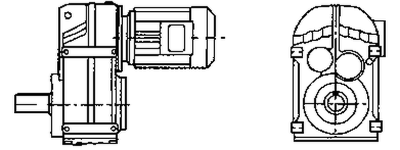
Record access openings and safe lifting reach; verify a workable installed and service configuration; shortest product length does not always give shortest replacement downtime.
Use parallel offset for packaging
An F-unit can locate the motor beside a conveyor frame or machine housing; this may reduce axial projection but increase side clearance.
Moving the motor can collide with neighboring guards or pipes; overlay the full parallel-shaft assembly including terminal box.
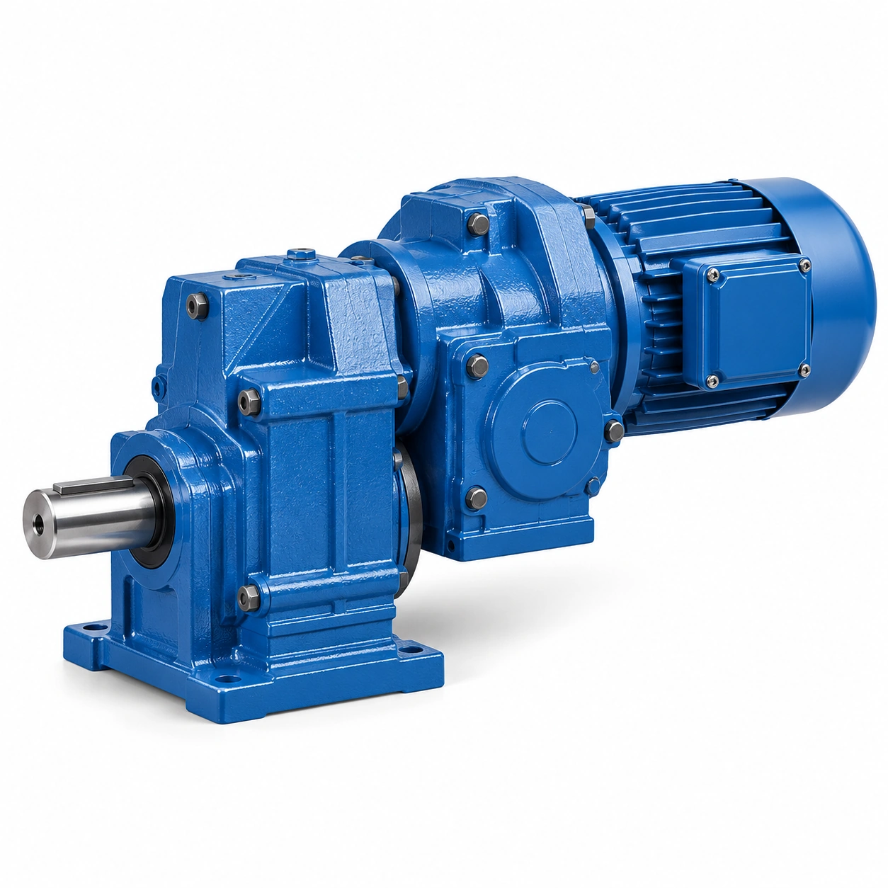
Check actual output axis, housing envelope and reaction support; approve the design in a clash-checked machine model; a parallel arrangement does not guarantee a smaller total machine.
Compare hollow output construction
Parallel-shaft arrangements often have hollow bore options for direct shaft mounting; eliminating an external coupling changes fit, support and torque restraint.
A direct fit may increase the consequences of shaft fretting; provide key, bore and machine shaft tolerances.
Check drive-shaft bearing scheme and axial retention; accept only a mechanically supported connection; a nominal bore match does not establish correct torque transfer.
Understand structural mounting
An inline foot mount and a shaft-mounted parallel unit create different force paths; the latter may require a torque arm with controlled movement.
A support designed for one may be unsuitable for the other; trace housing reaction to the machine frame.

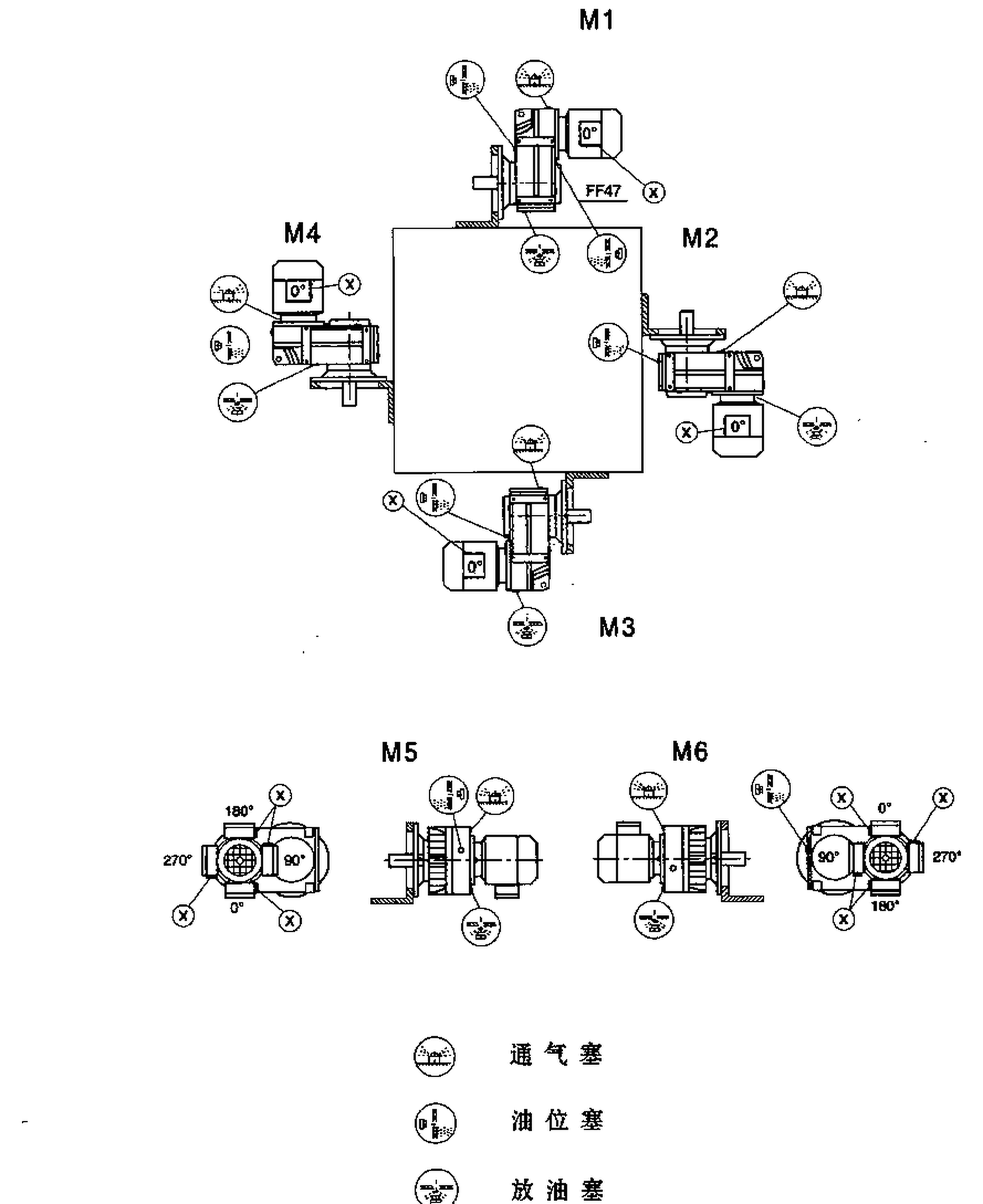
Inspect foot, flange and torque-arm constraints; approve support loads and movement before choosing the size; unplanned reaction forces can disturb alignment and seals.
The latter may require a torque arm with controlled movement. A support designed for one may be unsuitable for the other. Examine the inline and parallel-shaft comparison layout example. Inspect foot, flange and torque-arm constraints. Approve support loads and movement before choosing the size.
Assess radial load at the output
A pulley or sprocket can introduce load independent of torque; shaft projection and bearing spacing vary by construction.
Using a torque-only figure to compare layouts is incomplete; compute radial force and lever arm for both arrangements.

Request allowed Fr and Fa at the same operating point; compare output support on common design assumptions; a seemingly compact choice may need extra bearings.
Compare lubrication and heat
Different housings and installed orientations can require different oil arrangements; a gearbox in a cramped horizontal bay may lose cooling airflow.
A generic family efficiency ranking does not prove suitability; specify rpm, continuous duty, position and ambient conditions.
Obtain mounting-specific oil and thermal evidence for each option; check equal-load thermal performance before final selection; a correct mechanical interface may still run too hot.
Preserve access for service
An alternative arrangement may simplify one task but obstruct another; oil-level plugs, seals and motor fans must remain accessible.
An excellent package layout is not automatically serviceable; model removal paths and inspection points for both candidates.


Review the configuration with maintenance technicians; select an option with an acceptable service method; maintenance access should be a real design criterion.
Illustrative engineering scenario: Industrial packaging or conveyor machinery with competing drive envelopes
An OEM wants to make a packaging machine narrower. The existing inline helical gearmotor extends away from the main machine frame and obstructs a planned access corridor. A parallel-shaft F-series option seems to allow the motor to sit alongside the roller, but the redesign is not just a space-saving substitution. The mechanical designer establishes fixed machine datums, then places both complete drive envelopes over the same driven-shaft centerline. This exposes the different offsets, mounting reactions, cable clearances and service corridors. A model that saves length might increase width where a control cabinet is already installed.
The inline arrangement currently uses a flexible coupling and two machine shaft bearings. The proposed parallel-shaft version could use a hollow output directly mounted on the roller shaft, removing the coupling. That changes the way torque is transferred and can alter bearing loading. A keyed or frictional locking connection must be dimensioned with the correct engagement and retention features. The gearbox housing needs a reaction restraint if shaft-mounted. The arm should carry housing torque without imposing an unintended rigid secondary support on the output shaft. The design team asks the manufacturer for permissible external radial and axial loads at the relevant shaft position and output speed.
Maintenance compares access as a real sequence. For the inline unit, the motor can be withdrawn axially after coupling disconnection. For the F-series alternative, a close-fitting bore may require a puller and sufficient space to slide the housing off the shaft. Oil ports and output seals must remain reachable behind guards. The apparent compactness of the layout could be lost if servicing the drive requires removal of the entire conveyor. The procurement comparison therefore includes the extra restraint, shaft-fit parts, possible machine bearings and extraction hardware.
The final selection considers actual ratio, torque, heat, support and installation geometry under identical machine duty. The team does not accept unverified claims that one family is always more efficient or stronger. Either may be right depending on the constructed machine. The winning option is the one whose mechanical interface and maintenance path are fully documented and whose manufacturer ratings cover the operating envelope with the least unapproved structural change.
The analysis is especially important if the shaft-mounted option is suspended directly on a conveyor roller. Shaft deflection may shift gearbox alignment while the torque arm follows a separate motion. A detailed drawing should indicate the permissible joint movement and the location of fixed and floating bearings. When those pieces are not yet defined, the F-family layout remains a concept under review, not a proven drop-in replacement. Maintenance input should be collected before the machine frame is fabricated.
The OEM can then compare future service costs without inventing savings: how many guards are removed, which lifting equipment is needed, how long an oil change or seal extraction might take, and what spare interfaces must be stocked. These questions give parallel-shaft and inline options the same operational basis. The best geometric choice is the one that solves a genuine constraint without creating a less visible support or service problem.
Five-stage review for industrial packaging or conveyor machinery with competing drive envelopes
-
Draw axis geometry firstEstablish machine datums and draw both shaft axes. Choose an envelope that clears the process equipment.
-
Check coaxial coupling accessRecord access openings and safe lifting reach. Shortest product length does not always give shortest replacement downtime.
-
Compare hollow output constructionProvide key, bore and machine shaft tolerances. Accept only a mechanically supported connection.
-
Assess radial load at the outputRequest allowed Fr and Fa at the same operating point. A seemingly compact choice may need extra bearings.
-
Preserve access for serviceModel removal paths and inspection points for both candidates. Select an option with an acceptable service method.
Engineering comparison matrix: inline vs parallel shaft helical gearbox
| Engineering question | Evidence to collect | Review decision |
|---|---|---|
| Draw axis geometry first | Measure offset distance and available motor length. | Choose an envelope that clears the process equipment. |
| Check coaxial coupling access | Record access openings and safe lifting reach. | Verify a workable installed and service configuration. |
| Use parallel offset for packaging | Check actual output axis, housing envelope and reaction support. | Approve the design in a clash-checked machine model. |
| Compare hollow output construction | Check drive-shaft bearing scheme and axial retention. | Accept only a mechanically supported connection. |
| Understand structural mounting | Inspect foot, flange and torque-arm constraints. | Approve support loads and movement before choosing the size. |
| Assess radial load at the output | Request allowed Fr and Fa at the same operating point. | Compare output support on common design assumptions. |
Frequently Asked Questions
Which is more compact, inline or parallel-shaft helical gearing?
Does an F-series hollow output eliminate the need for separate bearings?
How is lubrication affected by the layout choice?
What does a fair comparison include besides envelope size?
What makes a final review credible for industrial packaging or conveyor machinery with competing drive envelopes?
A gearbox in a cramped horizontal bay may lose cooling airflow. When comparing actual mounting geometry, use the inline and parallel-shaft comparison configuration options. Obtain mounting-specific oil and thermal evidence for each option.
Model removal paths and inspection points for both candidates. For an engineering quotation that records the open conditions, contact the technical team about inline and parallel-shaft comparison. Select an option with an acceptable service method.
Engineering sources for Inline or Parallel Shaft Helical Gearbox — Layout Comparison
For the inline or parallel shaft helical gearbox: layout comparison workflow, consult these reference documents alongside the actual model installation manual:
- Inline or Parallel Shaft Helical Gearbox: Layout Comparison: SEW-EURODRIVE, Dimension sheet information (analysis).
- Inline or Parallel Shaft Helical Gearbox: Layout Comparison: SEW-EURODRIVE, Basic calculation process (interface review).
- Inline or Parallel Shaft Helical Gearbox: Layout Comparison: SEW-EURODRIVE, Change of mounting position (acceptance checks).