

Buyer takeaway
Belt pull, drum diameter, loading method, stopping strategy and dirt ingress determine the true demand on the reducer. Estimating pull from an empty conveyor creates a hidden mechanical undersize risk. Refer to the belt conveyor drive sizing guidance. For an overview of reducer configurations, see the helical gearbox selection overview before discussing a model-specific rating. Record tight-side and slack-side tension or an engineering estimate with the source and operating case. A supplier should review rated and starting torque against the calculated duty.
Start with effective belt pull
Identify output shaft side load
Connect braking and reverse rollback
Start with effective belt pull
The tangential force at the head pulley determines the driven drum torque; a long loaded belt and a short steep belt can require different tractive forces despite equal motor power.
Estimating pull from an empty conveyor creates a hidden mechanical undersize risk; measure material rate, gradient, belt resistance and expected full-load running conditions.


Record tight-side and slack-side tension or an engineering estimate with the source and operating case; confirm the calculated torque is within a specific rated reducer duty envelope; using nominal motor power alone may hide starting and operating loads.
Convert pulley radius into output torque
A drum transmits torque at its pitch radius, which depends on the effective diameter; for an illustrative 4 kN effective belt pull and 0.2 m radius, the required drum torque is 800 N m before design margins.
Confusing drum diameter with radius doubles the apparent torque requirement; use torque equal to tangential force multiplied by effective pulley radius.
Document the measured radius, tension method and whether the drum has a coating; a supplier should review rated and starting torque against the calculated duty; selecting against a guessed pulley size creates an avoidable error in all downstream comparisons.
Map loaded restart and jams
Conveyors do not always start empty and trapped material may resist initial movement; a belt stopped under a full load can demand a higher transient torque than one already moving.
Ignoring acceleration and jam clearing can overstate the available gearbox reserve; characterize the start profile, ramp time, stops per hour and maximum plugged condition.

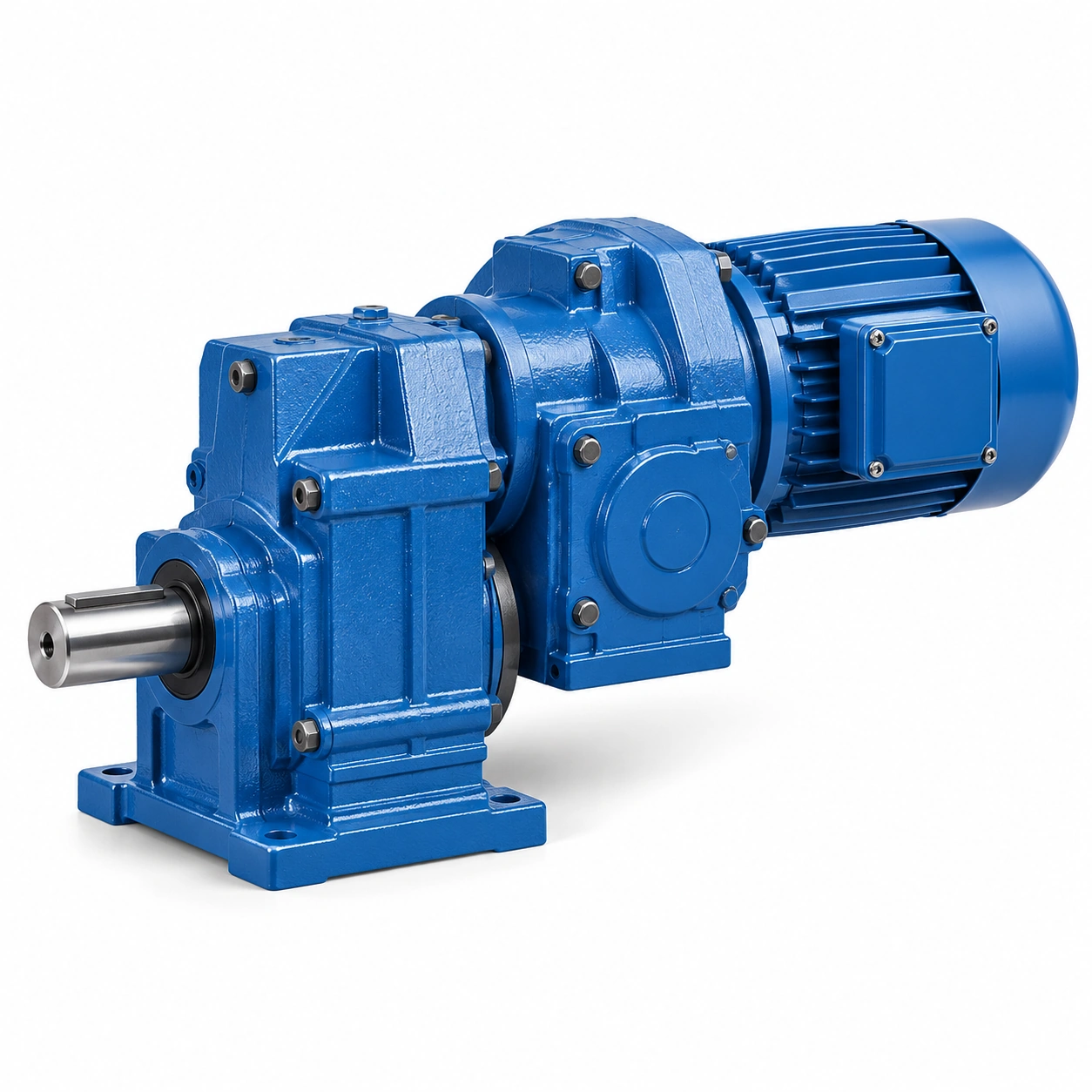
Keep starting current trends and VFD ramp settings with the drive record; transient torque, protection and motor limits should be approved together; an electrical current limit does not independently certify the gear tooth peak capacity.
Identify output shaft side load
A belt pulley applies radial force to a shaft and its bearings in addition to transmitted torque; an outboard drive pulley with a large overhang produces bending even at moderate shaft torque.
Missing the load application point can invalidate a quoted allowable radial force; draw belt force vectors and dimension their point of action from the gearbox bearing.

Request the reducer maker allowable Fr at that lever arm and output rpm; approve the support arrangement only after the bearing load and required life are reconciled; a gearbox can pass the torque calculation and still overload its output bearings.
Choose parallel or inline geometry
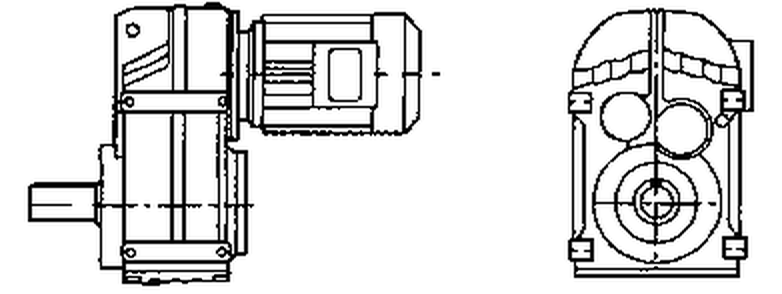
The motor location is constrained by the guard, walkway, drum centerline and surrounding transfer chute; an F-series arrangement may fit beside a conveyor frame where an inline package extends beyond it.
Moving the reducer without verifying reaction forces can create a service or safety obstruction; compare R-type coaxial and F-type parallel-shaft arrangements on the real machine drawing.
Measure clearance for motor withdrawal, fill plugs, lifting access and torque reaction restraint; choose the package whose mounting and maintenance envelope is actually compatible; the smallest illustrated housing is not automatically the easiest drive to maintain.
An F-series arrangement may fit beside a conveyor frame where an inline package extends beyond it. Moving the reducer without verifying reaction forces can create a service or safety obstruction. Examine the belt conveyor drive sizing layout example. Measure clearance for motor withdrawal, fill plugs, lifting access and torque reaction restraint. Choose the package whose mounting and maintenance envelope is actually compatible.
Assess heat and contaminant exposure
Dust deposited on a housing can interfere with cooling while grit attacks seals; a conveyor near wet screening equipment presents different cleaning and ventilation needs from a dry store conveyor.
An unverified IP label or unspecified seal option cannot establish suitability; provide ambient temperature, run hours, dust level and washdown procedures in the enquiry.


Document enclosure ventilation and the approved lubricant for the proposed mounting position; thermal and sealing acceptance should be based on configuration-specific manufacturer data; an acceptable output torque alone cannot guarantee continuous thermal operation.
Connect braking and reverse rollback
Sloping conveyors may develop reverse load when power is lost or the drive stops; holding equipment and backstops have to be coordinated with the real slope and tension distribution.
Relying on gear friction for rollback control may expose personnel and machinery; specify stopping direction, reverse torque and required behavior under power failure.
Obtain backstop or brake specification and the control sequence from the responsible integrator; verify the complete safety function rather than an isolated reducer feature; a gearbox description cannot substitute for a verified machine rollback system.
Commission under representative throughput
A no-load run can conceal belt slip, high torque and heat build-up at production throughput; full-load testing should reflect the maximum intended material flow and permissible ramp.
Accepting on smooth unloaded rotation alone leaves several failure modes untested; record rpm, motor current, vibration, oil condition and belt tracking at defined loads.

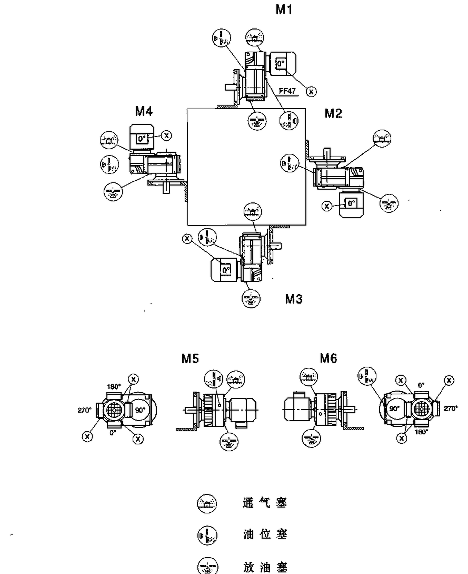
Build a baseline with conditions and measurement locations to support future trending; the accepted drive should remain stable and within approved limits across the defined test states; without a documented loaded baseline later maintenance diagnosis becomes guesswork.
Illustrative engineering scenario: A loaded industrial belt conveyor
Consider a hypothetical belt conveyor transporting a granular material to a storage silo. The engineering team records an effective tangential belt force of 4,000 N at the head drum during a representative loaded run. If the drum's effective pitch radius is 0.20 m, the torque at the drum is 800 N m before allowances for acceleration, friction changes or process disturbances. That number is a starting point, not a purchase-ready reducer rating. The planner next documents the operating speed, the expected peak during a loaded restart, how frequently material can jam the chute and the true service hours during the busiest season. The required reducer output cannot be fixed until these conditions are assembled into the machine load case.
The same conveyor has a belt pulley mounted outside the nearest driven-shaft bearing. That geometry may place a substantial radial load on the shaft even when the calculated transmitted torque seems unremarkable. On the assembly drawing, dimension the center of the belt force from the bearing and specify the direction of the force relative to the housing. A bidder should return allowable shaft-load information at the actual output speed and expected bearing-life basis. If those figures are missing, adding a larger motor or increasing the nominal gearbox torque does not resolve the bearing question. The designer may instead need a separately supported pulley shaft with a coupling from the gearbox output.
Now consider an installation where material spillage accumulates around the housing and ambient air is warmer under a protective guard. Oil selection, heat rejection and seal access become part of the decision, not optional notes appended after ordering. The manufacturer must confirm the thermal duty for the chosen operating point and mounting orientation. A realistic commissioning plan starts with guarded no-load checks, then progressively increases throughput while recording motor current, belt tracking, noise, shaft speed and case temperature. The result is an acceptance record that can be compared with future maintenance measurements; it is not a universal claim about F-series capacity.
Five-stage review for a loaded industrial belt conveyor
-
Start with effective belt pull
Measure material rate, gradient, belt resistance and expected full-load running conditions. Confirm the calculated torque is within a specific rated reducer duty envelope. -
Convert pulley radius into output torque
Document the measured radius, tension method and whether the drum has a coating. Selecting against a guessed pulley size creates an avoidable error in all downstream comparisons. -
Identify output shaft side load
Draw belt force vectors and dimension their point of action from the gearbox bearing. Approve the support arrangement only after the bearing load and required life are reconciled. -
Assess heat and contaminant exposure
Document enclosure ventilation and the approved lubricant for the proposed mounting position. An acceptable output torque alone cannot guarantee continuous thermal operation. -
Commission under representative throughput
Record rpm, motor current, vibration, oil condition and belt tracking at defined loads. The accepted drive should remain stable and within approved limits across the defined test states.
Engineering comparison matrix: helical gearbox for belt conveyor
| Engineering question | Evidence to collect | Review decision |
|---|---|---|
| Start with effective belt pull | Record tight-side and slack-side tension or an engineering estimate with the source and operating case. | Confirm the calculated torque is within a specific rated reducer duty envelope. |
| Convert pulley radius into output torque | Document the measured radius, tension method and whether the drum has a coating. | A supplier should review rated and starting torque against the calculated duty. |
| Map loaded restart and jams | Keep starting current trends and VFD ramp settings with the drive record. | Transient torque, protection and motor limits should be approved together. |
| Identify output shaft side load | Request the reducer maker allowable Fr at that lever arm and output rpm. | Approve the support arrangement only after the bearing load and required life are reconciled. |
| Choose parallel or inline geometry | Measure clearance for motor withdrawal, fill plugs, lifting access and torque reaction restraint. | Choose the package whose mounting and maintenance envelope is actually compatible. |
| Assess heat and contaminant exposure | Document enclosure ventilation and the approved lubricant for the proposed mounting position. | Thermal and sealing acceptance should be based on configuration-specific manufacturer data. |
Frequently Asked Questions
Does the drum radius affect the specified gearbox torque?
Why is a belt pulley radial load separate from transmitted torque?
Should a conveyor reducer be accepted from a no-load test?
Which drawings should accompany a conveyor gearbox enquiry?
What makes a final review credible for a loaded industrial belt conveyor?
Holding equipment and backstops have to be coordinated with the real slope and tension distribution. When comparing actual mounting geometry, use the belt conveyor drive sizing configuration options. Obtain backstop or brake specification and the control sequence from the responsible integrator.
Record rpm, motor current, vibration, oil condition and belt tracking at defined loads. For an engineering quotation that records the open conditions, contact the technical team about belt conveyor drive sizing. The accepted drive should remain stable and within approved limits across the defined test states.
Next step: Engineering enquiry
Engineering sources for Helical Gearbox Selection for Industrial Belt Conveyors
For the helical gearbox selection for industrial belt conveyors workflow, consult these reference documents alongside the actual model installation manual:
- Helical Gearbox Selection for Industrial Belt Conveyors: ISA, Selecting the Optimal Conveyor Drive (analysis).
- Helical Gearbox Selection for Industrial Belt Conveyors: SEW-EURODRIVE, Basic calculation process (interface review).
- Helical Gearbox Selection for Industrial Belt Conveyors: SEW-EURODRIVE, Application-specific service factor (acceptance checks).