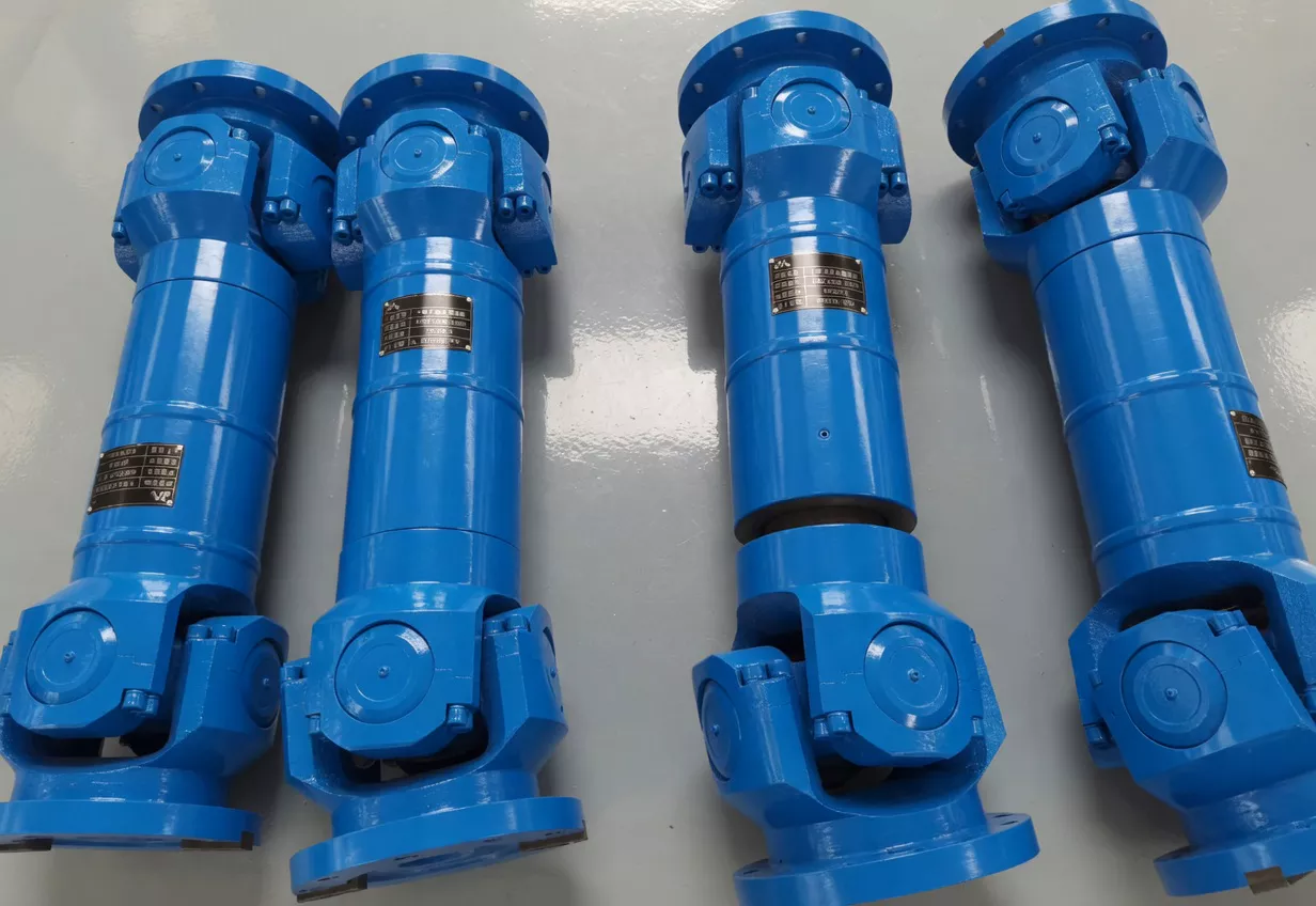
SWP-E Long Flexible Double Flange Universal Joint Couplings — Product Overview
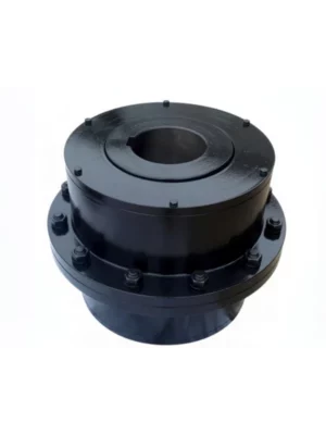
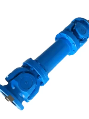
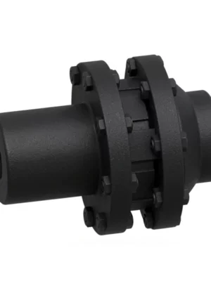
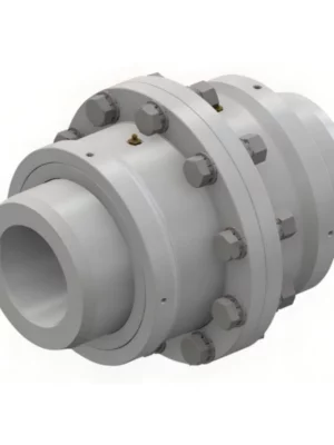
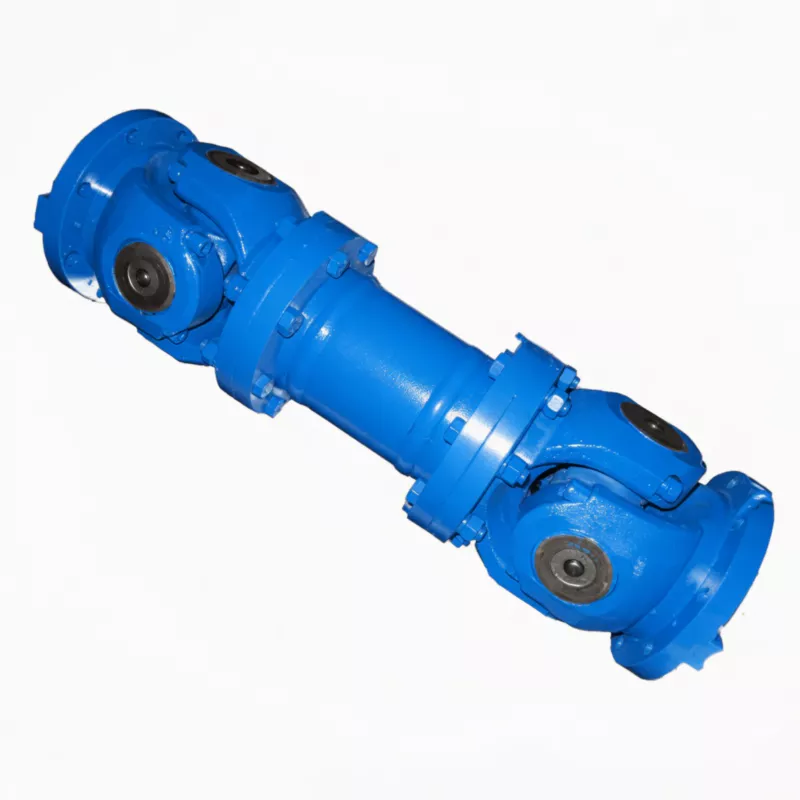
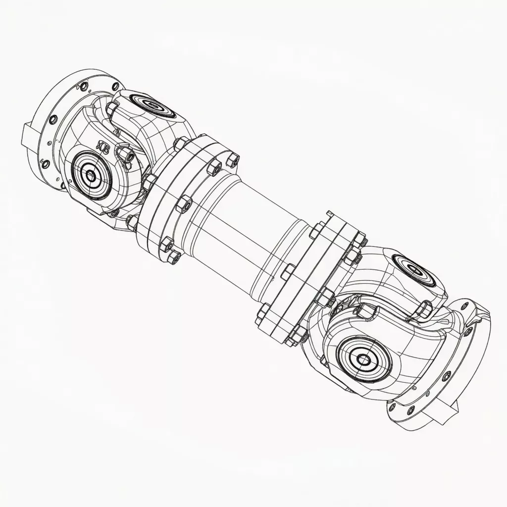
The SWP-E Long Flexible Double Flange Universal Joint Coupling is the most specialised variant in the SWP series. It combines the long telescoping body of SWP-A with a double flange yoke configuration — a design that presents two concentric bolt circles on the coupling flange instead of the single bolt circle found on SWP-A through SWP-D.
The double flange design is found on specific rolling mill gearbox outputs, large industrial drive stands, and heavy lifting machinery where the increased bolting surface distributes coupling-to-shaft torque loads more effectively, and where OEM equipment specifications mandated the double flange as standard.
Telescoping stroke (Ls) of 50 to 230 mm, fold angle ≤10°, and gyration diameters 160 to 640 mm are retained identically from SWP-A. The long body (Lmin 715–3 170 mm) positions SWP-E as the longest standard type in the family.
Key distinction from SWP-A: SWP-E Lmin values are consistently longer than SWP-A at the same diameter (e.g., SWP315E Lmin 1345 mm vs SWP315A at 1250 mm). This extended length accommodates the additional depth of the double flange yoke assembly.
When these OEM couplings require replacement or upgrading, SWP-E provides the correct double flange interface through a locally supportable supply chain, eliminating dependence on single-source OEM parts.
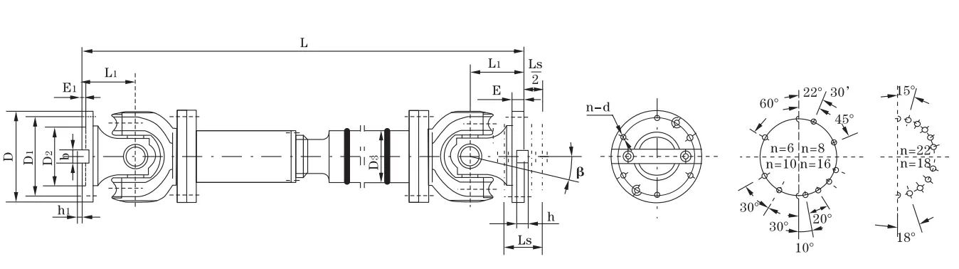
Technical Specifications
| Type |
D (mm) |
Tn (kN·m) |
Tf (kN·m) |
Ls (mm) |
β |
Lmin (mm) |
D1 js11 |
D2 H7 |
D3 |
E |
E1 |
b×h |
h1 |
L1 |
n–d |
I Lmin (kg·m²) |
ΔI/100mm |
G Lmin (kg) |
ΔG/100mm |
| SWP160E |
160 |
16 |
8 |
50 |
≤10 |
715 |
140 |
95 |
114 |
15 |
4 |
20×12 |
6 |
85 |
6–13 |
0.15 |
0.0059 |
49 |
2.1 |
| SWP180E |
180 |
20 |
10 |
60 |
≤10 |
800 |
155 |
105 |
121 |
15 |
4 |
24×14 |
7 |
95 |
6–15 |
0.25 |
0.0072 |
69 |
2.3 |
| SWP200E |
200 |
31.5 |
16 |
70 |
≤10 |
880 |
175 |
125 |
127 |
17 |
5 |
28×16 |
8 |
110 |
8–15 |
0.42 |
0.0114 |
81 |
3.4 |
| SWP225E |
225 |
40 |
20 |
76 |
≤10 |
1000 |
196 |
135 |
152 |
20 |
5 |
32×18 |
9 |
130 |
8–17 |
0.75 |
0.029 |
108 |
6.6 |
| SWP250E |
250 |
63 |
31.5 |
80 |
≤10 |
1055 |
218 |
150 |
168 |
25 |
5 |
40×25 |
12.5 |
135 |
8–19 |
1.26 |
0.0407 |
179 |
7.3 |
| SWP285E |
285 |
90 |
45 |
100 |
≤10 |
1210 |
245 |
170 |
194 |
27 |
7 |
40×30 |
15 |
150 |
8–21 |
2.67 |
0.0702 |
285 |
9.4 |
| SWP315E |
315 |
140 |
63 |
110 |
≤10 |
1345 |
280 |
185 |
219 |
32 |
7 |
40×30 |
15 |
170 |
10–23 |
4.38 |
0.1144 |
375 |
12.0 |
| SWP350E |
350 |
180 |
90 |
120 |
≤10 |
1480 |
310 |
210 |
245 |
35 |
8 |
50×32 |
16 |
185 |
10–23 |
7.42 |
0.1663 |
488 |
13.6 |
| SWP390E |
390 |
250 |
112 |
120 |
≤10 |
1623 |
345 |
235 |
273 |
40 |
8 |
70×36 |
18 |
205 |
10–25 |
13.27 |
0.2695 |
662 |
18.0 |
| SWP435E |
435 |
355 |
160 |
150 |
≤10 |
1860 |
385 |
255 |
299 |
42 |
10 |
80×40 |
20 |
235 |
16–28 |
24.62 |
0.3645 |
1107 |
20.0 |
| SWP480E |
480 |
450 |
224 |
170 |
≤10 |
2122 |
425 |
275 |
351 |
47 |
12 |
90×45 |
22.5 |
265 |
16–31 |
42.81 |
0.7028 |
1302 |
28.0 |
| SWP550E |
550 |
710 |
315 |
190 |
≤10 |
2338 |
492 |
320 |
402 |
50 |
12 |
100×45 |
22.5 |
290 |
16–31 |
68.81 |
1.1842 |
2140 |
35.7 |
| SWP600E |
600 |
1000 |
500 |
210 |
≤10 |
2930 |
544 |
380 |
450 |
55 |
15 |
90×55 |
27.5 |
360 |
22–34 |
110.6 |
1.7159 |
2703 |
40.5 |
| SWP640E |
640 |
1250 |
630 |
230 |
≤10 |
3170 |
575 |
385 |
480 |
60 |
15 |
100×60 |
30 |
385 |
18–38 |
177.77 |
2.308 |
3719 |
48.3 |
Note: D=315mm, L=1800mm → SWP315E×1800. Lmin values exceed SWP-A equivalents due to double flange yoke depth. Ls = telescoping stroke (50–230 mm). ΔI and ΔG are incremental values per 100 mm length above Lmin.
Industry Applications
⚙️ Hot Rolling Mill Main Drives — Double Flange Gearboxes
Working condition: Very high torque (>500 kN·m on main stands), continuous high-cycle operation, thermal growth of roll necks and gearbox housing, OEM equipment with double flange output specification.
Why SWP-E: When the OEM gearbox presents a double flange output (two concentric bolt circles), SWP-E is the geometrically correct match. The double flange distributes torque-induced flange loads across a larger bolting diameter, reducing per-bolt stress at high torque levels.
Customer benefit: Direct OEM replacement with standard interface; no gearbox modification required; full torque rating maintained.
Wire Rod & Bar Mill Finishing Stands
Working condition: High-speed, moderate torque, compact stands with double flange spindle interfaces, frequent roll guide changes.
Why SWP-E: Wire rod finishing stand spindle couplings with double flange interfaces require precise dimensional matching to OEM specifications. SWP-E provides the correct double flange geometry with standard SWP spider crosses that are interchangeable with other SWP types in the same facility.
Customer benefit: Compatible with existing spindle stands without modification; standard SWP spider crosses enable shared spare parts inventory with other SWP types across the plant.
⚙️ Large Industrial Gearbox Driven Equipment
Working condition: Specialised gearbox configurations with double flange output shafts, medium-to-high torque, variable operating speed.
Why SWP-E: Custom industrial gearbox manufacturers in Germany, Italy, and Japan routinely specify double flange output shafts for their high-torque products.
Customer benefit: OEM-independent replacement supply chain; reduced procurement lead time versus single-source OEM parts; competitive pricing.
Heavy Plate Leveller Drives
Working condition: Very high torque per roll, bidirectional loading, frequent thickness changes requiring roll gap adjustment (axial movement compensation required).
Why SWP-E: Plate leveller spindles with double flange interfaces and axial movement during roll gap adjustment are precisely the application SWP-E was designed for. The combination of extended body length, full telescoping stroke, and double flange yoke addresses all three requirements simultaneously.
Customer benefit: Complete spindle coupling solution for double flange leveller drives; no compromise on torque capacity or axial stroke versus OEM design.
How to Choose: SWP-E vs SWP-A
SWP-E selection is primarily driven by the interface geometry of the connected equipment. If your gearbox or machinery presents a double flange connection face, SWP-E is the required type. Torque sizing follows the same method as SWP-A.
| Selection Criterion |
SWP-E Applies |
SWP-A Applies Instead |
| Equipment flange interface |
Double flange (two bolt circles or wide flange) |
Standard single yoke flange |
| Shaft span requirement |
Long (715–3170 mm) |
Long (660–2685 mm) but SWP-E is longer |
| Axial displacement required |
Yes (Ls 50–230 mm) |
Yes — same stroke as SWP-E |
| Angular compensation |
≤10° (same as SWP-A) |
≤10° |
| OEM equipment replacement |
OEM had double flange spindle |
OEM had standard SWP-A type spindle |
Torque and Stroke Sizing — Same Method as SWP-A
Torque sizing for SWP-E follows the same method as SWP-A: T_design = T_nominal × KA, where KA values range from 1.25 (smooth, steady load) to 2.5 (crusher, hoist with shock loading).
⚠️ SWP-E Specification Errors to Avoid
- Specifying SWP-E where SWP-A interface fits: The double flange configuration is only an advantage where the connected equipment has a matching double flange face. Specifying SWP-E for standard single-yoke applications adds unnecessary length, weight, and cost without benefit.
- Ignoring Lmin increase versus SWP-A: SWP-E Lmin values are 7–18% longer than SWP-A at the same diameter. If installation space is close to SWP-A Lmin, verify there is sufficient clearance before upgrading to SWP-E.
- Mismatching bolt circle dimensions: Double flange interfaces can vary between equipment manufacturers. Always verify the bolt circle diameter, number of bolts, and bolt size of the connected equipment flange before ordering SWP-E — a dimension mismatch makes the coupling unusable without modification.
Have an OEM rolling mill or industrial drive with a double flange spindle coupling? Contact Our Engineers with your flange drawing and we'll verify dimensional compatibility.
Why Choose RP for SWP-E Supply
SWP-E is our premium rolling mill spindle coupling, engineered to OEM-equivalent quality for the most demanding double flange drive applications in steel and wire rod production worldwide.
Rolling Mill Engineering Expertise
We have supplied SWP-E double flange couplings as replacement parts and new-build components to rolling mills in China, India, Southeast Asia, and beyond for over 20 years. Our engineers maintain a cross-reference database of major rolling mill OEM coupling dimensions.
Flange Precision Manufacturing
Double flange yokes are machined on 5-axis CNC machining centres, with bolt hole true position held to ±0.05 mm versus nominal bolt circle. Flange faces are ground perpendicular to the bore axis to Ra ≤1.6 μm.
OEM Cross-Reference Service
We maintain a cross-reference database of major rolling mill OEM coupling dimensions (European, Japanese, and domestic makes). For replacement orders, submit your existing coupling drawing or measurement report and we will verify dimensional compatibility before manufacturing.
Supply Chain Assurance
SWP-E components in sizes D160–D390 are held in semi-finished stock for fast assembly. Lead time for standard sizes: 10–20 business days. For larger sizes (D435–D640), 4–6 weeks production time.
Customer Reviews & Case Studies
We urgently needed replacement spindle couplings for our finishing block drives — original OEM parts had a 16-week lead time. RP matched our double flange dimensions from drawings within one day and delivered in four weeks. Fitted perfectly, running without issue.
India — Hot Strip Mill Main Drive Replacement, Maharashtra ★★★★★
We cross-referenced our European OEM spindle couplings and ordered SWP480E as replacements. RP confirmed dimensional compatibility before manufacturing. Installation went smoothly with no shimming or modification required.
— Maintenance Manager, Maharashtra Hot Strip Mill
South Korea — Plate Leveller Drive Retrofit, Pohang ★★★★☆
Specified SWP390E for a leveller spindle upgrade. The double flange and telescoping stroke combination was exactly what the design required. Minor feedback: we had to request custom bolt hole positions, which added lead time.
— Project Mechanical Engineer, Korean Plate Mill
Turkey — Bar Mill Finishing Stand Overhaul ★★★★★
We purchase SWP-E couplings annually for our rolling mill overhaul programme. Quality is consistently excellent, dimensional repeatability from batch to batch is very good, and the documentation package meets our audit requirements.
— Purchasing Manager, Turkish Steel Bar Mill
Frequently Asked Questions
How do I verify that SWP-E is dimensionally compatible with my existing double flange equipment?
The key dimensions to verify are: (1) bolt circle diameter (B.C.D.) — must match within ±0.5 mm; (2) number and size of flange bolts; (3) total flange outer diameter (for guard clearance); (4) gyration diameter and bore dimensions (D1, D2). Submit your OEM coupling drawing and we will perform dimensional verification against our SWP-E range before order confirmation.
Can SWP-E be supplied with one double flange end and one standard yoke end?
Yes. Asymmetric configurations — double flange on the machine side and standard yoke on the motor/gearbox side — are available as custom orders. This is common in retrofits where only one end of the drivetrain presents a double flange interface.
What is the difference in weight and inertia between SWP-E and SWP-A at the same size?
SWP-E is heavier and has higher rotational inertia than SWP-A at the same gyration diameter, due to the additional flange material and longer overall body. Example at D315: SWP315E weighs approximately 15–20% more than SWP315A at the same installed length.
What greasing schedule is recommended for SWP-E in continuous rolling mill service?
For hot rolling mill main drive service (24/7 continuous, elevated ambient temperature): re-grease spider needle bearings every 250–400 operating hours; re-grease telescoping spline every 300–500 hours. Use high-temperature lithium-complex grease rated to 150°C for mill environments.
Is SWP-E available with a flanged intermediate tube (SWP-E2 configuration)?
The standard SWP-E has a welded intermediate tube with double flange yoke ends as described in the JB/T 3241-91 specification. For modified configurations with flanged intermediate connections, please contact our engineering team with your specific requirements.
Enquire About SWP-E Couplings Today
Source SWP-E Double Flange Couplings for Your Rolling Mill or Industrial Drive
Whether you need a direct OEM replacement or a custom double flange spindle for a new-build project, our engineering team will match your dimensional requirements and deliver to your schedule.
Submit OEM Drawing for Cross-Reference
Request Urgent Supply
ISO 9001:2015 · Rolling Mill OEM Cross-Reference Service