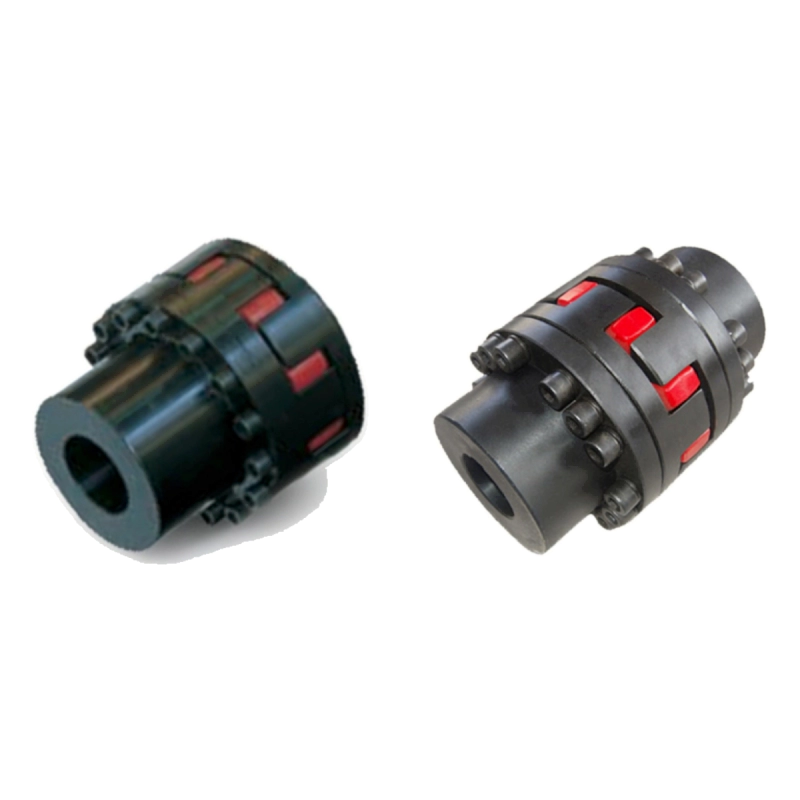
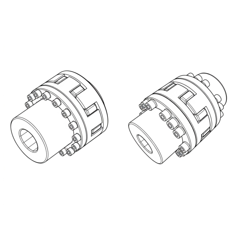
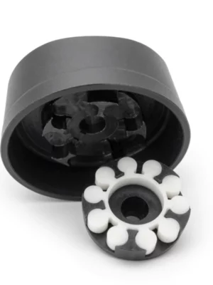
EP-SF / EP-DF Single and Double Flange Jaw Flexible Coupling — Heavy Machinery Flange Connections
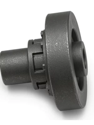
The EP-SF and EP-DF series provide the jaw flexible coupling technology of the EP platform in a configuration purpose-built for flanged connections found in heavy industrial machinery. Both designs use a bolt-circle flange on one or both sides of the coupling body to mount directly to flywheel flanges, pump flanges, or gearbox output flanges — a connection geometry common in large pumps, compressors, mixers, and marine auxiliary drives where standard shaft-to-shaft couplings are not practical.
The EP-SF single-flange variant is particularly notable for its maintenance advantage: because the radial flange can be released and the coupling body slid off in the axial direction, the elastomeric spider can be inspected and renewed without any movement of the driving or driven equipment. This is a significant benefit in installations where the machinery is large, heavy, or pipework-constrained — situations where moving an electric motor or a pump body even a few centimetres involves substantial preparatory work. The EP-SF requires the drive to be isolated but not moved to carry out an elastomer replacement.
The EP-DF double-flange variant takes this concept further: both flanges are radial, so the entire coupling can be assembled and disassembled purely in the radial direction. This is invaluable in confined installations — for example, between a close-coupled pump and motor where axial access is blocked by a wall or by piping — where the drive and driven equipment cannot be separated axially at all.
Key Features & Design Characteristics
⚙
Elastomer damping
The resilient spider helps absorb shock and torsional vibration between the driving and driven hubs.
✓
Lubrication-free element
The elastomeric transmission element does not require routine grease lubrication.
⇄
Compact hub arrangement
The jaw-style construction provides a short, practical connection for many motor-to-machine layouts.
Simple service access
Spider condition, hub fit and alignment can be checked during normal maintenance without complex disassembly procedures.
Structural Characteristics
- Flange connection suitable for heavy-machinery applications.
- Radial flange removal enables purely radial installation — no axial access required (EP-DF).
- EP-SF elastomer replacement without moving the active or driven equipment.
- Drive must be isolated but not repositioned for elastomer service.
- Bore, keyway, and flange configuration customisable per customer requirement.
- Covers sizes from EP24 to EP180, torque range 35 to 19,650 N·m.
Technical Specifications — EP-SF / EP-DF Combined
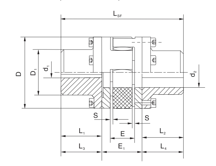
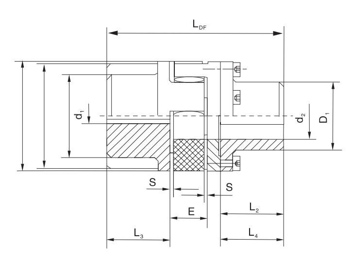
| Model | Torque (N·m) | Speed (rpm) | Bore d (mm) | D (mm) | D1 (mm) | D2 (mm) | E (mm) | S (mm) | L_SF (mm) | L_DF (mm) |
|---|
| EP24SF/DF | 35 | 14000 | 8–24 | 55 | 36 | 40 | 18 | 2 | 94 | 86 |
| EP28SF/DF | 95 | 11800 | 8–28 | 65 | 42 | 48 | 20 | 2.5 | 110 | 100 |
| EP38SF/DF | 190 | 9500 | 10–38 | 80 | 52 | 66 | 24 | 3 | 134 | 124 |
| EP42SF/DF | 265 | 8000 | 10–42 | 95 | 62 | 75 | 26 | 3 | 150 | 138 |
| EP48SF/DF | 310 | 7100 | 10–48 | 105 | 70 | 85 | 28 | 3.5 | 164 | 152 |
| EP55SF/DF | 410 | 6300 | 15–55 | 120 | 80 | 98 | 30 | 4 | 192 | 176 |
| EP65SF/DF | 625 | 5600 | 15–65 | 135 | 94 | 115 | 35 | 4.5 | 217 | 201 |
| EP75SF/DF | 1280 | 4750 | 20–75 | 160 | 108 | 135 | 40 | 5 | 248 | 229 |
| EP90SF/DF | 2400 | 3750 | 30–90 | 200 | 142 | 160 | 45 | 5.5 | 285 | 265 |
| EP100SF/DF | 3300 | 3350 | 30–115 | 225 | 158 | 180 | 50 | 6 | 320 | 295 |
| EP110SF/DF | 4800 | 3000 | 40–125 | 255 | 178 | 200 | 55 | 6.5 | 347 | 321 |
| EP125SF/DF | 6650 | 2650 | 40–145 | 290 | 206 | 230 | 60 | 7 | 400 | 370 |
| EP140SF/DF | 8600 | 2360 | 40–160 | 320 | 235 | 256 | 65 | 7.5 | 443 | 409 |
| EP160SF/DF | 12800 | 2000 | 60–180 | 370 | 270 | 290 | 75 | 9 | 501 | 463 |
| EP180SF/DF | 19650 | 1800 | 85–200 | 420 | 315 | 325 | 85 | 10.5 | 555 | 515 |
SF vs. DF — Choosing the Right Variant
| Feature | EP-SF | EP-DF |
|---|
| Flange configuration | Single radial flange | Double radial flanges |
| Elastomer replacement method | Axial, without moving machinery | Radial, no axial access needed |
| Axial installation space needed | Moderate | Minimal |
| Drive must be isolated? | Yes | Yes |
| Drive must be moved? | No | No |
| Overall length (example EP90) | 285 mm | 265 mm |
For complementary shaft-to-shaft solutions, browse the jaw coupling range or explore the full coupling catalogue.
Customer Reviews & Case Studies
Netherlands — Large Pump Station
A water management authority in Zuid-Holland installed EP-SF couplings on twelve vertical turbine pump sets. The ability to replace elastomeric spiders without disconnecting the pipework or moving the motors reduced scheduled maintenance from a two-day to a four-hour operation per pump.
★★★★★
"The SF design was the deciding factor in selecting these couplings for our pump stations." — Chief Mechanical Engineer
United Kingdom — Industrial Compressor OEM
A screw compressor manufacturer in Yorkshire standardised on EP-DF for their 75 kW to 250 kW range. The radial assembly principle allowed their customers to replace elastomers in cramped compressor rooms where axial access to the coupling was completely unavailable.
★★★★★
"Our service engineers report the EP-DF as one of the easiest couplings to service in the field." — Service Manager
Spain — Marine Auxiliary Systems
A shipyard near Valencia specified EP-SF and EP-DF couplings for bilge pump and ballast pump drives across a series of offshore supply vessels. The flange-mount design matched the existing flywheel flanges directly, eliminating the need for custom adapter plates.
★★★★☆
"Bolt-circle dimensions were delivered exactly to our drawings — no rework required." — Outfitting Supervisor
Frequently Asked Questions
What is the main difference between EP-SF and EP-DF?
The EP-SF uses a single radial flange on one side; after releasing the flange bolts the coupling body slides axially to allow elastomer access. The EP-DF uses radial flanges on both sides, enabling the complete coupling and its elastomeric spider to be assembled and removed entirely in the radial direction — no axial clearance between the machines is required at all. Use EP-SF when some axial access is available; use EP-DF when the machines are constrained axially.
Does the SF design really allow elastomer replacement without moving the motor?
Yes — this is the core maintenance advantage of the EP-SF. With the drive isolated, the flange bolts are removed, the coupling body is slid axially a short distance, and the spider is withdrawn and replaced. The motor and the driven machine remain on their baseplate without any mechanical repositioning. This significantly reduces both the downtime and the labour involved in routine elastomer maintenance compared with couplings that require machine movement.
Are EP-SF and EP-DF interchangeable for the same flange bolt-circle?
Both variants share the same outer diameter D and flange bolt-circle geometry for a given size, so the mating flange on the machine does not need to change. However, the overall axial length differs between SF and DF — the DF is slightly shorter. Before substituting one type for the other, always compare the L_SF and L_DF dimensions in the specification table to verify the available space is adequate.
Can custom flange bolt patterns be manufactured?
Yes. Non-standard bolt-circle diameters, numbers of bolts, flange thicknesses, and flange outer diameters can be manufactured to customer-specific drawings. This makes the EP-SF/DF suitable for retrofit projects where existing machinery flanges do not match standard bolt-circle dimensions. Please provide a flange drawing and dimensional data when requesting a quotation.
What torque range is covered by the EP-SF/DF series?
The series spans from the EP24SF/DF at 35 N·m up to the EP180SF/DF at 19,650 N·m, at maximum allowable speeds from 14,000 rpm (smallest size) down to 1,800 rpm (largest size). This range covers the majority of industrial pump, compressor, blower, and marine auxiliary drive applications.
Request Flange Coupling Information
EP welcomes enquiries from OEM manufacturers, engineering contractors, and distributors for the EP-SF/DF range. Custom flange dimensions, bore specifications, and technical drawing support are available. Contact us to discuss your project.
Contact Us for Flange Coupling Enquiries
Applications
◆
Pumps & fans
Used in motor-driven rotating equipment where compact size and vibration damping are useful.
⚙
Conveyors & packaging
Applicable to start-stop machinery where shock absorption and straightforward maintenance are valued.
⇄
HVAC & utilities
Suitable for auxiliary drives where shaft alignment and elastomer condition can be checked during service.
✓
General automation
Considered for industrial motion systems when torque, bore size, speed and misalignment remain within the selected model limits.