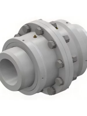
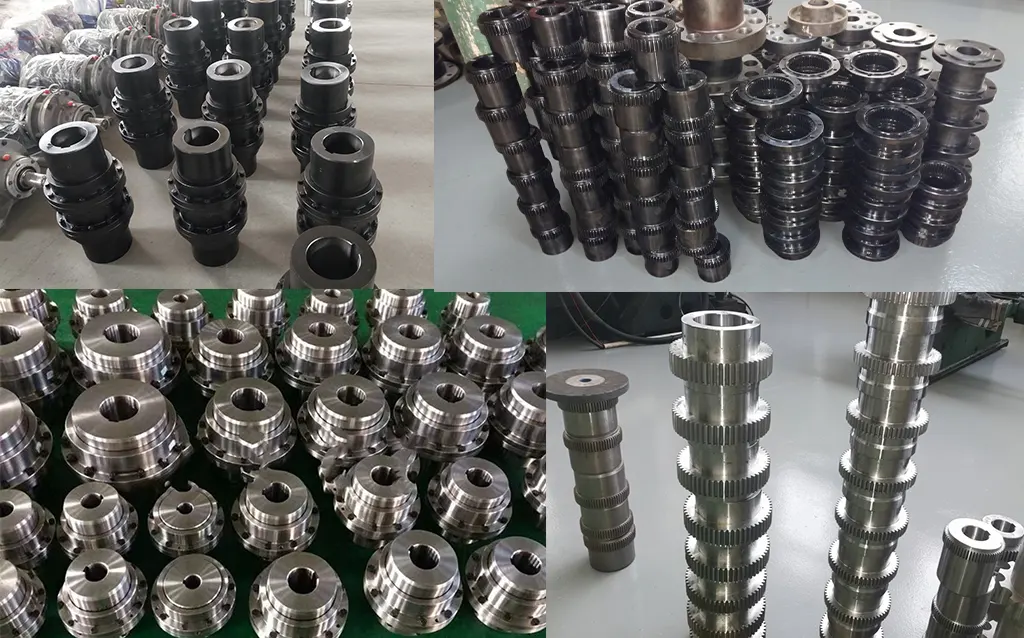
NGCLZ Drum Shape Gear Coupling with Brake Drum — Intermediate Shaft Type
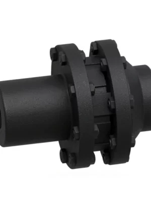
Three-in-one drive component: crowned-tooth gear coupling, integral shoe-brake drum, and intermediate shaft spacer — purpose-built for mine hoists, cranes, and heavy-drive systems with extended shaft separation.
Torque Range
355 – 100000 KN·m
Speed Rating
Up to 4000 RPM
Sizes Available
14 (NGCLZ1–14)
Brake Drum D0
160 – 800 mm
Bore Combinations
Y/Y · Y/J · Z1/J1 · J1/J1
Product Overview
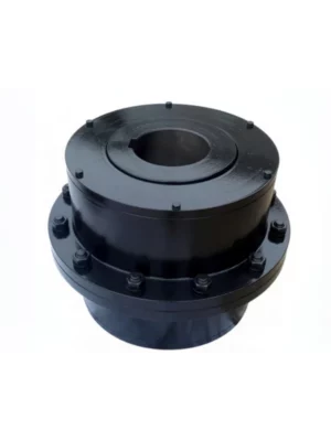
The NGCLZ drum shape gear coupling with brake drum is the intermediate-shaft variant of the NGCL series — a three-function power transmission component that simultaneously transmits torque through two crowned gear meshes, provides an integral D0 cylindrical brake drum surface for a shoe brake assembly, and bridges the gap between motor and gearbox shaft ends through its intermediate shaft.
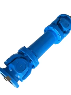
Where the NGCL is used when motor and gearbox shaft ends are closely adjacent, the NGCLZ is the engineering choice when those shaft ends are separated by a meaningful distance — a common layout in mine hoists, heavy cranes, and industrial drives where the gearbox is mounted away from the motor for structural or accessibility reasons.
Technical Definition and Working Principle
What the NGCLZ Is — and What Sets It Apart
The NGCLZ is a crowned-tooth gear coupling in the NGCL brake drum family, with the 'Z' suffix denoting the inclusion of an intermediate shaft (the connecting spacer tube between the two coupling halves).
This configuration produces two distinct gear meshes in series. Each mesh accommodates angular misalignment independently, so the NGCLZ's total angular compensation capacity is approximately twice that of a single-mesh coupling — making it more forgiving of shaft-to-shaft misalignment across a longer span.
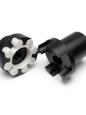
The key differentiator from a straight-tooth gear coupling is the crowned (drum-shaped) tooth profile. A straight-tooth coupling transmits torque via a full-face line contact that concentrates stress at the tooth edge when angular misalignment is present — leading to accelerated wear and tooth breakage under the shock loading typical of hoist applications.
The Three Functions of the NGCLZ
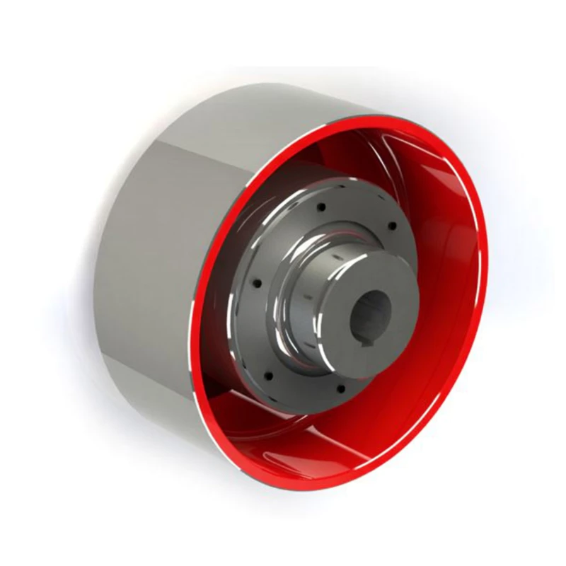
- Torque Transmission: Crowned gear teeth on both hub halves mesh with internal straight teeth in the sleeve flanges of the intermediate shaft. Torque flows: motor shaft → hub 1 crowned teeth → sleeve 1 internal teeth → intermediate shaft → sleeve 2 internal teeth → hub 2 crowned teeth → driven shaft.
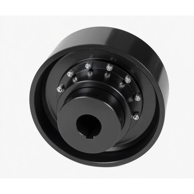
- Brake Drum Surface: One coupling half (typically the motor side) is machined with an extended outer flange forming the D0 cylindrical brake drum surface. A shoe brake assembly clamps its brake blocks against this surface to decelerate or hold the drive train. D0 ranges from 160 mm to 800 mm across the NGCLZ series.
- Shaft Spacing: The intermediate shaft bridges the physical gap between motor and driven machine shaft ends. This enables equipment layouts that the close-coupled NGCL cannot serve, and facilitates axial withdrawal of either machine for maintenance without disturbing the other's mounting alignment.
Shaft Bore Combination Options
Unlike most gear couplings that offer a single bore type per half, the NGCLZ supports four factory-standard bore combination options. This flexibility allows a single NGCLZ size to serve a wide range of motor and gearbox shaft configurations without custom machining.
| Combination |
Motor Side |
Driven Side |
Typical Use |
| Y / Y |
Y cylindrical |
Y cylindrical |
Both shafts are standard cylindrical with keyway; most common general-purpose configuration |
| Y / J |
Y cylindrical |
J1 cylindrical (long) |
Motor with standard Y shaft, gearbox or drum with longer J1 shaft; mixed motor/gearbox shaft standards |
| Z1 / J1 |
Z1 conical taper (1:10) |
J1 cylindrical |
IEC motor with conical shaft end (Z1); preferred for high-cycle reversing or high-shock applications where keyless taper fit prevents fretting |
| J1 / J1 |
J1 cylindrical (long) |
J1 cylindrical (long) |
Both shafts require long-engagement cylindrical bore; maximum bore engagement length on both sides |
Comparison with Other Coupling Types
| Feature |
NGCLZ (this product) |
Jaw Coupling |
Disc Coupling |
Rigid Flange |
| Integral Brake Drum |
Yes — D0 shoe brake surface |
No |
No |
No |
| Intermediate Shaft |
Yes — standard feature |
No |
Spacer option available |
No |
| Angular Misalignment |
1.0–1.5 deg per mesh (two meshes) |
Up to 1 deg |
Up to 1 deg |
Near zero |
| Torque Range |
355 – 100000 KN·m |
Low–Medium |
Medium |
High |
| Shock Load Tolerance |
Excellent |
Good (elastomer) |
Poor |
Transmitted fully |
| Axial Machine Withdrawal |
Yes — remove spacer shaft |
No |
Spacer disc types only |
No |
| Suitable for Hoisting / Crane |
Yes — purpose-designed |
No |
No |
No |
NGCL vs NGCLZ — Which Should You Choose?
Both the NGCL and NGCLZ are drum shape gear couplings with integrated brake drums, share the same torque ratings, and conform to JB/T7003-93. The decision between them comes down to drivetrain geometry: NGCL for close-coupled shafts, NGCLZ when a shaft spacer is needed.
| Comparison Factor |
NGCL (Close-Coupled) |
NGCLZ (Intermediate Shaft) |
| Intermediate Shaft |
No |
Yes (standard) |
| Shaft-to-Shaft Gap |
Short — shafts closely adjacent |
Extended — shafts can be far apart |
| Gear Meshes |
1 pair |
2 pairs (higher misalignment) |
| Angular Misalignment |
1.0–1.5 deg (one mesh) |
Up to 3 deg (two meshes combined) |
| Brake Drum (D0) |
Integral on one half |
Integral on one half |
| Machine Removal for Maintenance |
Requires full coupling separation |
Remove spacer shaft — motor or gearbox withdraws axially |
| Bore Combinations |
Z1 or J1 / Y |
Y/Y, Y/J, Z1/J1, J1/J1 |
| Overall Length |
Shorter (B3) |
Longer (B3 + intermediate shaft) |
| Choose When... |
Shaft ends are closely spaced and B3 length fits the layout |
Shaft ends are separated; maintenance withdrawal space is needed; higher misalignment is expected |
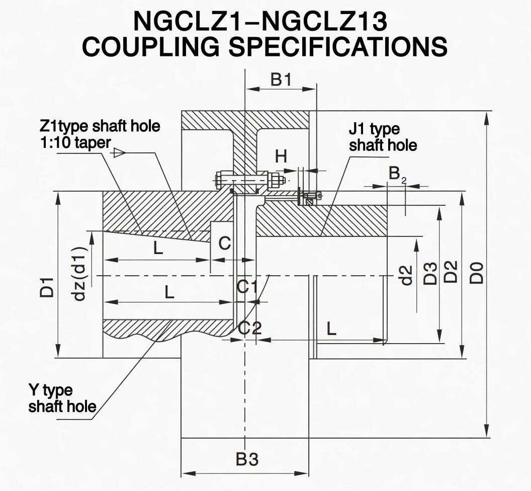
Specifications & Size Matrix — NGCLZ1 to NGCLZ14
All specifications are from the NGCLZ catalogue per JB/T7003-93. Dimensions in millimetres. D0 is the brake drum outer diameter. B2 is the seal replacement clearance dimension. Bracketed D0 values indicate both drum diameters are available for that size.
NGCLZ1 – NGCLZ9 Specifications
| Type |
Torque
(KN·m) |
Speed
(R/min) |
d1, d2
(mm) |
Y |
J1, Z1 |
D0
(brake) |
D |
D1 |
D2 |
C |
C1 |
H |
B |
B1 |
B2 |
B3 |
Inertia
(Kg·m²) |
Weight
(Kg) |
| NGCLZ1 |
355 |
4000 |
20, 22, 24 |
52 |
38 |
160 |
103 |
71 |
71 |
50 |
30 |
8 |
2 |
42 |
38 |
68 |
0.071 |
7.3 |
| 25, 28 |
62 |
44 |
0.072 |
7.4 |
| 30, 32, 35 |
82 |
60 |
0.076 |
8.4 |
| NGCLZ2 |
630 |
4000 |
25, 28 |
62 |
44 |
160 |
115 |
83 |
83 |
60 |
39 |
8 |
2 |
48 |
42 |
68 |
0.081 |
9.2 |
| 30, 32, 35, 38 |
82 |
60 |
0.084 |
10.3 |
| 40, 42, 45 |
112 |
84 |
0.088 |
10.5 |
| NGCLZ3 |
1000 |
3800 |
28 |
62 |
44 |
200 |
127 |
95 |
95 |
75 |
39 |
8 |
2 |
49 |
42 |
85 |
0.181 |
15.1 |
| 30, 32, 35, 38 |
82 |
60 |
0.184 |
16.3 |
| 40, 42, 45, 48, 50, 55 |
112 |
84 |
0.193 |
18.8 |
| NGCLZ4 |
1600 |
3800 |
38 |
82 |
60 |
200 |
149 |
116 |
116 |
90 |
46 |
8 |
2 |
53 |
42 |
85 |
0.225 |
19.8 |
| 40, 42, 45, 48, 50, 55, 56 |
112 |
84 |
0.242 |
23.3 |
| 60, 63, 65 |
142 |
107 |
0.296 |
26.8 |
| NGCLZ5 |
2800 |
3000 |
40–56 |
112 |
84 |
250 |
167 |
134 |
134 |
105 |
47 |
9 |
2.5 |
58 |
42 |
105 |
0.596 |
33.3 |
| 60–75 |
142 |
107 |
0.627 |
39 |
| NGCLZ6 |
4500 |
3000 |
45–56 |
112 |
84 |
250 |
187 |
153 |
153 |
125 |
52 |
9 |
2.5 |
59 |
42 |
105 |
0.72 |
40 |
| 60–75 |
142 |
107 |
0.776 |
46.4 |
| 80, 85, 90 |
172 |
132 |
0.837 |
53.2 |
| NGCLZ7 |
6300 |
2400 |
50, 55, 56 |
112 |
84 |
315 (300) |
204 |
170 |
170 |
140 |
52 |
9 |
2.5 |
63 |
42 |
132 |
1.178 |
51.8 |
| 60–75 |
142 |
107 |
1.254 |
59.8 |
| 80, 85, 90, 95 |
172 |
132 |
1.348 |
68.2 |
| 100 |
212 |
167 |
1.479 |
79.6 |
| NGCLZ8 |
9000 |
1900 |
55, 56 |
112 |
84 |
400 |
230 |
186 |
186 |
155 |
57 |
12 |
3 |
77 |
47 |
168 |
3.734 |
84 |
| 60–75 |
142 |
107 |
3.86 |
93.1 |
| 80, 85, 90, 95 |
172 |
132 |
3.996 |
104 |
| 100, 110 |
212 |
167 |
4.187 |
117 |
| NGCLZ9 |
14000 |
1500 |
60–75 |
142 |
107 |
500 |
256 |
212 |
212 |
180 |
64 |
13 |
3 |
47 |
47 |
210 |
9.43 |
133 |
| 80, 85, 90, 95 |
172 |
132 |
9.663 |
146 |
| 100, 110, 120, 125 |
212 |
167 |
9.997 |
164 |
| 130 |
252 |
202 |
10.3 |
182 |
NGCLZ10 – NGCLZ14 Specifications
| Type |
Torque
(KN·m) |
Speed
(R/min) |
d1, d2
(mm) |
Y |
J1, Z1 |
D0
(brake) |
D |
D1 |
D2 |
C |
C1 |
H |
B |
B1 |
B2
(seal) |
B3 |
Inertia
(Kg·m²) |
Weight
(Kg) |
| NGCLZ10 |
20000 |
1200 |
65, 70, 71, 75 |
142 |
107 |
630 (600) |
287 |
239 |
200 |
120 |
65 |
15 |
3.5 |
90 |
47 |
265 |
28.238 |
176 |
| 80, 85, 90, 95 |
172 |
132 |
28.509 |
190 |
| 100, 110, 120, 125 |
212 |
167 |
28.879 |
209 |
| 130, 140, 150 |
252 |
202 |
29.248 |
237 |
| NGCLZ11 |
31500 |
1050 |
70, 71, 75 |
142 |
107 |
710 (700) |
325 |
276 |
235 |
134 |
77 |
16 |
3.5 |
94 |
47 |
298 |
44.309 |
257 |
| 80, 85, 90, 95 |
172 |
132 |
44.825 |
275 |
| 100, 110, 120, 125 |
212 |
167 |
45.53 |
300 |
| 130, 140, 150 |
252 |
202 |
46.235 |
326 |
| 160, 170 |
302 |
242 |
47.08 |
357 |
| NGCLZ12 |
45000 |
1050 |
75 |
142 |
107 |
710 (700) |
362 |
313 |
270 |
164 |
94 |
17 |
4 |
104 |
49 |
298 |
47.88 |
306 |
| 80, 85, 90, 95 |
172 |
132 |
48.29 |
317 |
| 100, 110, 120, 125 |
212 |
167 |
49.52 |
351 |
| 130, 140, 150 |
252 |
202 |
50.25 |
384 |
| 160, 170, 180 |
302 |
242 |
52.22 |
425 |
| 190, 200 |
325 |
282 |
53.69 |
464 |
| NGCLZ13 |
63000 |
950 |
150 |
252 |
202 |
800 |
412 |
350 |
300 |
165 |
88 |
18 |
4.5 |
113 |
49 |
335 |
82.7 |
490 |
| 160, 170, 180 |
302 |
242 |
84.7 |
544 |
| 190, 200, 220 |
352 |
282 |
86.67 |
596 |
| NGCLZ14 |
100000 |
950 |
170, 180 |
302 |
242 |
800 |
462 |
420 |
335 |
209 |
92 |
20 |
5.5 |
157 |
63 |
335 |
99.1 |
670 |
| 190, 200, 220 |
352 |
282 |
102.2 |
736 |
| 240, 250 |
410 |
330 |
105.9 |
785 |
Notes: B2 is the axial clearance dimension for seal replacement. Bracketed D0 values (e.g. 315/300, 630/600, 710/700) indicate both drum diameters are available for that size — verify with your shoe brake supplier before ordering.
Custom Bore, Intermediate Shaft Length & Brake Drum Size Available
Non-standard bore diameters, Z1 taper configurations, modified intermediate shaft lengths, and alternative D0 dimensions are all achievable to drawing. Contact our engineering team with your drivetrain drawing.
Technical Advantages — Why Crowned Tooth Outperforms Straight Tooth
Longer Service Life Under Shock Loads and Brake Applications
Mine hoists and crane hoist drives experience two types of severe loading simultaneously: torsional shock during load pickup, and combined torsional plus braking stress during emergency stops. The NGCLZ's crowned tooth profile distributes both loading types as Hertzian contact patches rather than concentrating them at tooth edges — significantly reducing peak tooth stress under both conditions.
Reduced Bearing Loads
A misaligned straight-tooth coupling transmits bending moments into both motor and gearbox bearings at 2× running frequency. In hoist applications, these forces add to the inherent radial loads from rope tension — compounding bearing fatigue. The NGCLZ's crowned tooth self-centres under load, generating substantially lower parasitic radial bearing forces.
Suitable for High-Speed Applications
Smaller NGCLZ sizes (NGCLZ1 through NGCLZ6) are rated to 3000–4000 RPM — appropriate for direct 4-pole motor coupling on 50 Hz supplies. The intermediate shaft is balanced as part of the complete coupling assembly.
Manufacturing & Quality Assurance
Manufacturing Highlights
NGCLZ couplings are manufactured from forged alloy steel blanks — 42CrMo4 for NGCLZ8 and above, 45# carbon steel for smaller sizes. The D0 brake drum surface and the crowned gear teeth are machined from the same forging, ensuring concentricity between the braking surface and the gear axis.
Crowned tooth profiles are generated on CNC gear hobbing machines with dedicated crowned tooling, achieving DIN Class 7 accuracy. The intermediate shaft is turned and bored to H7 tolerance on both end connections for accurate assembly.
The brake drum surface receives a dedicated finish-turning pass after heat treatment to achieve Ra 1.6–3.2 μm — the surface roughness specification required for consistent shoe brake operation and predictable brake shoe wear.
Quality Control Flow
STEP 1
Incoming Material & Spectrometer Check
STEP 2
Forging, Rough Turning, CNC Hobbing
STEP 3
Carburising, Quenching & Tempering
STEP 4
CMM, Tooth Profile, D0 Runout & Hardness
STEP 5
Assembly Balance Check, Paint & Export Pack
Certifications
Why Source Your NGCLZ Couplings from RP?