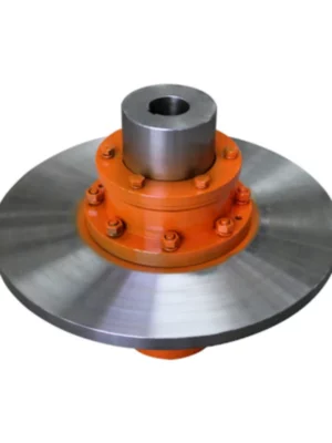
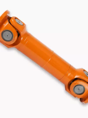
GIICLZ Drum Shape Gear Coupling: engineering overview
This page reorganizes the technical information for GIICLZ Drum Shape Gear Coupling around the decisions a buyer or engineer normally has to make: duty, shaft interface, alignment, installation envelope, inspection and model selection. All model values are retained in the reference blocks below.
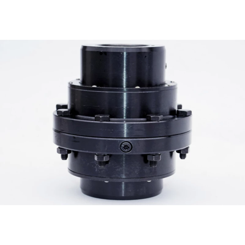
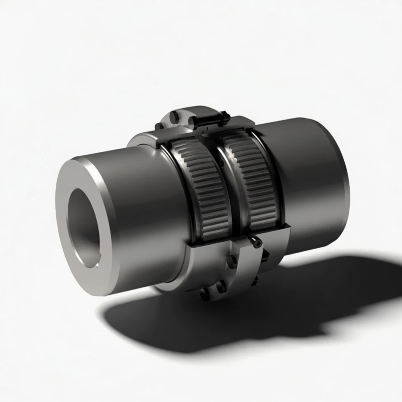
This coupling transfers torque through meshing external and internal teeth. Crowned or drum-shaped tooth geometry gives the mesh room to accommodate limited angular, axial and installation offset while retaining the high torque density expected from an all-metal coupling. The tooth contact and lubricant film are therefore central to both capacity and service life.
Key Features & Design Characteristics
⚙
Crowned-tooth engagement
Gear-tooth contact is designed to transmit torque while allowing limited shaft misalignment within the selected model limits.
✓
High torque density
The geared connection provides a compact mechanical path for industrial power transmission.
⇄
Misalignment accommodation
Hub and sleeve geometry is selected with angular, axial and parallel displacement requirements in mind.
Maintainable drive element
Lubrication, tooth condition, seals and fasteners can be included in planned inspection routines.
How this version is configured
Gear couplings are well suited to high-load drive trains, but they are not maintenance-free. Misalignment changes the contact pattern across the tooth flanks, and excessive offset can raise tooth-edge stress, heat and bearing reaction forces. Operating behavior depends on tooth geometry, speed, lubricant condition, sleeve construction and the shaft connection on both sides.
- The configuration should be matched to the exact shaft connection, available space and duty shown in the model data below.
Selection sequence for a real machine
Size the coupling from transmitted torque after applying an appropriate service factor for starts, reversals, shock and driven-equipment characteristics. Then verify maximum speed, shaft bore range, hub length, outside diameter and available axial space. If the version includes a brake drum, brake disc, spacer or intermediate sleeve, confirm that those added dimensions match the surrounding machine and brake arrangement.
- Define continuous torque, starting torque and any short-duration peak load instead of selecting from motor power alone.
- Confirm rotational speed and check whether balance, centrifugal loading or critical-speed limits affect the chosen size.
- Match every shaft interface: bore diameter, key or locking method, hub length, flange pilot, bolt pattern and available assembly clearance.
- Review angular, axial and parallel displacement separately. A coupling that tolerates one form of movement may have a much lower limit for another.
- Check the surrounding equipment for guards, brakes, bearings, seals and maintenance access before freezing the final outside diameter and overall length.
- Use the exact model matrix for the final dimensional decision; do not interpolate a bore, torque or speed value that is not listed.
Technical Specifications & Dimensions
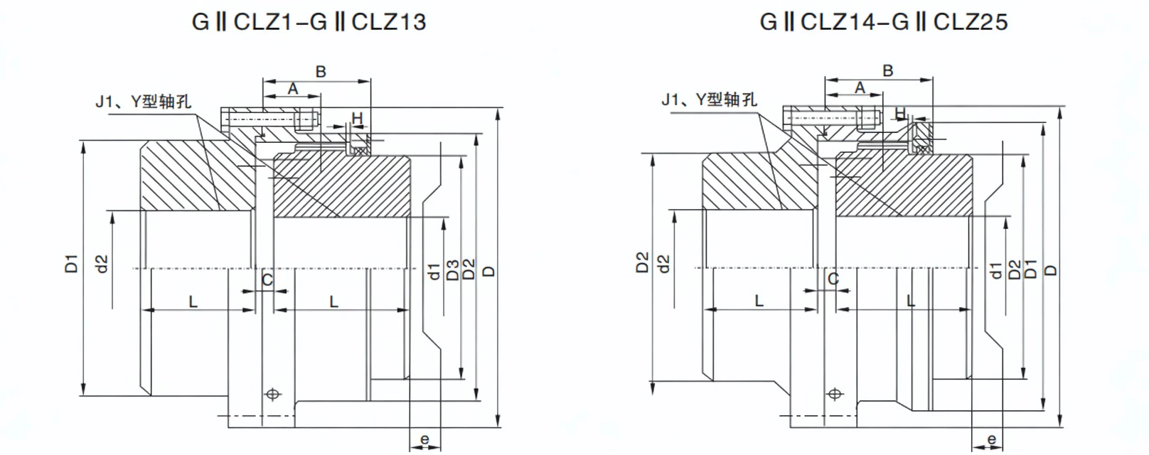
Use the tables below as the dimensional and model reference. Confirm bore, shaft fit, speed, torque and installation envelope before final selection.
| Feature |
GIICLZ Drum Gear |
Jaw Coupling |
Disc Coupling |
Grid Coupling |
| Max Torque Capacity |
Very High (to 4500 KN·m) |
Low-Medium |
Medium |
Medium-High |
| Angular Misalignment |
1.0-1.5 deg per mesh |
Up to 1 deg |
Up to 1 deg |
Up to 0.33 deg |
| Axial Displacement |
Yes (built-in) |
Limited |
Yes |
Yes |
| Shock Load Tolerance |
Excellent |
Good (elastomer absorbs) |
Poor |
Good |
| High-Speed Suitability |
Up to 4000 EPM |
Moderate |
High |
Moderate |
| Lubrication Required |
Yes |
No |
No |
Yes |
| Intermediate Shaft Option |
Standard (Z type) |
No |
Yes (spacer) |
Yes (spacer) |
| Typical Application Scale |
Heavy industrial |
Light-medium duty |
Precision drives |
Medium-heavy duty |
| Type |
Torque
(KN·m) |
Speed
(R/min) |
Shaft Bore d1, d2 |
Y |
J1 |
D |
D1 |
D2 |
D3 |
C |
H |
A |
B |
e |
Inertia
(Kg·m²) |
Weight
(Kg) |
| GIICLZ1 |
0.4 |
4000 |
16,18,19 |
42 |
– |
103 |
71 |
71 |
50 |
8 |
2 |
18 |
38 |
38 |
0.004 |
3.5 |
| 20,22,24 |
52 |
38 |
0.00375 |
3.3 |
| 25,28 |
62 |
44 |
0.004 |
3.5 |
| 30,32,35,38* |
82 |
60 |
0.005 |
4.1 |
| 40*,42*,45*,48*,50* |
112 |
84 |
0.007 |
5.7 |
| GIICLZ2 |
0.71 |
4000 |
20,22,24 |
52 |
– |
115 |
83 |
83 |
60 |
8 |
2 |
21 |
44 |
42 |
0.00675 |
5.3 |
| 25,28 |
62 |
44 |
0.00625 |
4.8 |
| 30,32,35,38 |
82 |
60 |
0.007 |
5.7 |
| 40,42,45,48,50*,55*,56* |
112 |
84 |
0.008 |
7.2 |
| GIICLZ3 |
1.12 |
4000 |
22,24 – 38 |
52–82 |
–/44/60 |
127 |
95 |
95 |
75 |
8 |
2 |
22 |
45 |
42 |
0.009–0.011 |
3.8–7.8 |
| 40–56, 60*,63*,65*,70* |
112–142 |
84/107 |
0.01325–0.01675 |
9.8–12.5 |
| GIICLZ4 |
1.8 |
4000 |
38 – 55,56 |
82–112 |
60/84 |
149 |
116 |
116 |
90 |
8 |
2 |
24.5 |
49 |
42 |
0.02125–0.0255 |
10.5–13.5 |
| 60–75*, 80* |
142–172 |
107/132 |
0.039–0.04875 |
16.5–19.4 |
| GIICLZ5 |
3.15 |
4000 |
40–90* |
112–172 |
84–132 |
167 |
134 |
134 |
105 |
10 |
2.5 |
27.5 |
54 |
42 |
0.044–0.0625 |
18.1–28.5 |
| GIICLZ6 |
5.00 |
4000 |
45–105* |
112–212 |
84–167 |
187 |
153 |
153 |
125 |
10 |
2.5 |
28 |
55 |
42 |
0.075–0.1065 |
23.9–36.2 |
| GIICLZ7 |
7.1 |
3750 |
50–115* |
112–212 |
84–167 |
204 |
170 |
170 |
140 |
10 |
2.5 |
30 |
59 |
42 |
0.1145–0.1898 |
29.6–54.3 |
| GIICLZ8 |
10.0 |
3300 |
55–125* |
112–212 |
84–167 |
230 |
186 |
186 |
155 |
12 |
3 |
33.5 |
71 |
47 |
0.184–0.297 |
37.8–67.4 |
| GIICLZ9 |
16.0 |
3000 |
60–150* |
142–252 |
107–202 |
256 |
222 |
212 |
180 |
12 |
3 |
34.5 |
73 |
47 |
0.358–0.575 |
60–104.4 |
| Type |
Torque
(KN·m) |
Speed
(R/min) |
Shaft Bore d1, d2 |
Y |
L |
D |
D1 |
D2 |
D3 |
C |
H |
A |
B |
e |
Inertia
(Kg·m²) |
Weight
(Kg) |
| GIICLZ10 |
22.4 |
2650 |
65–150 |
142–252 |
107–202 |
287 |
239 |
239 |
200 |
14 |
3.5 |
39 |
82 |
47 |
0.58–0.935 |
76.1–133 |
| GIICLZ11 |
35.5 |
2350 |
110–200 |
212–352 |
167–282 |
325 |
250 |
276 |
235 |
14 |
3.5 |
40.5 |
85 |
47 |
1.223–1.625 |
137–193 |
| GIICLZ12 |
50 |
2100 |
130–200 |
252–352 |
202–282 |
362 |
286 |
313 |
270 |
16 |
4 |
44.5 |
95 |
49 |
2.39–3.093 |
212.8–290 |
| GIICLZ13 |
71 |
1850 |
150–225 |
252–352 |
202–282 |
412 |
322 |
350 |
300 |
18 |
4.5 |
49 |
104 |
49 |
3.93–6.34 |
272.3–370 |
| GIICLZ14 |
112 |
1650 |
170–250 |
302–410 |
242–330 |
462 |
420 |
335 |
– |
22 |
5.5 |
86 |
148 |
63 |
6.9–8.6 |
389–509 |
| GIICLZ15 |
180 |
1500 |
190–285 |
352–470 |
282–380 |
512 |
465 |
380 |
– |
22 |
5.5 |
91 |
158 |
63 |
12.425–15.575 |
566–740 |
| GIICLZ16 |
250 |
1300 |
220–320 |
352–470 |
282–380 |
580 |
522 |
430 |
– |
28 |
7 |
104.5 |
177 |
67 |
21.2–26.35 |
751–974 |
| GIICLZ17 |
355 |
1200 |
250–365 |
410–550 |
330–450 |
644 |
582 |
490 |
– |
28 |
7 |
99 |
182 |
67 |
38.825–49.5 |
1110–1465 |
| GIICLZ18 |
500 |
1050 |
280–400 |
470–650 |
380–540 |
726 |
658 |
540 |
– |
28 |
8 |
111 |
215 |
75 |
69.5–90.5 |
1580–2160 |
| GIICLZ19 |
710 |
950 |
300–470 |
470–650 |
380–540 |
818 |
748 |
630 |
– |
32 |
9 |
116 |
220 |
75 |
122.5–161.25 |
2115–2892 |
| GIICLZ20 |
1000 |
800 |
360–540 |
550–800 |
450–680 |
928 |
838 |
720 |
– |
32 |
10.5 |
123.5 |
235 |
75 |
240–335 |
3223–4680 |
| GIICLZ21 |
1400 |
750 |
400–600 |
650–800 |
540–680 |
1022 |
928 |
810 |
– |
40 |
11.5 |
127.5 |
245 |
75 |
435–527.75 |
4780–5905 |
| GIICLZ22 |
1800 |
650 |
450–680 |
650–900 |
540–780 |
1134 |
1036 |
915 |
– |
40 |
13 |
131 |
255 |
75 |
701.25–852.25 |
6069–7504 |
| GIICLZ23 |
2500 |
600 |
530–770 |
800–900 |
680–780 |
1282 |
1178 |
1030 |
– |
50 |
14.5 |
149.5 |
290 |
80 |
1415.75–1638.75 |
9633–11133 |
| GIICLZ24 |
3550 |
550 |
560–850 |
800–1000 |
680–880 |
1428 |
1322 |
1175 |
– |
50 |
16.5 |
158.5 |
305 |
80 |
2330.5–2976.25 |
12460–16110 |
| GIICLZ25 |
4500 |
460 |
670–1040 |
900–1000 |
780–1100 |
1644 |
1538 |
1390 |
– |
50 |
19 |
162.5 |
310 |
80 |
5174.25–7198.25 |
19837–27797 |
| Feature |
GICL |
GICLZ |
GIICL |
GIICLZ |
| Standard |
JB/T8854.3 |
JB/T8854.3 |
JB/T8854.2 |
JB/T8854.2 & .3 |
| Tooth Meshes |
1 pair drum teeth |
1 pair drum teeth |
2 pairs drum teeth |
2 pairs drum teeth |
| Intermediate Shaft |
No |
Yes |
No |
Yes |
| Misalignment Compensation |
Moderate |
Higher (spacer adds range) |
High (two meshes) |
Highest (two meshes + spacer) |
| Shaft Spacing |
Close-coupled |
Extended distance |
Close-coupled |
Extended distance |
| Structure Compactness |
Most compact |
Moderate |
Compact |
Longest overall |
| Typical Use |
Standard drives, small inertia |
Long-span drives |
High misalignment, compact |
Heavy-duty, long span, high misalignment |
| Recommended For |
General machinery |
Pump sets, fan drives |
Rolling mills, compressors |
Mining, steel, cement, power gen |
Standards and designation references found in the source data
Where a standard or designation is shown below, treat it as a reference tied to the original product data and verify the applicable revision when placing an order.
JB/T8854.2JB/T8854.3ISO 9001:2015
Shaft fit, alignment and assembly checks
Accurate shaft alignment at installation extends tooth and seal life even though the coupling can compensate for a limited amount of misalignment. Clean the gear teeth and lubricant cavity, check keys and hub fits, assemble seals without damage and tighten fasteners uniformly. After alignment, fill with the lubricant quantity and grade specified for the selected size and duty.
Measure the actual shaft diameters and keyways before machining or confirming a finished bore. A drawing should identify shaft tolerances, key dimensions, required hub position and any shoulder, locknut or axial-retention feature. Alignment readings should be taken after the machine is in its normal installed condition because base distortion, pipe strain, belt pull or thermal growth can move the shaft centers after an initial bench alignment.
After assembly, turn the drive through at least one full revolution by hand where practical. Check for interference with guards, brake hardware and adjacent structures, then verify fastener security. On equipment that changes temperature significantly between start-up and steady operation, compare cold and hot alignment expectations before setting final offsets.
Operating behavior and service planning
Routine checks should include lubricant leakage, seal condition, bolt security, abnormal noise, temperature rise and backlash growth. During planned shutdowns, inspect tooth flanks for pitting, fretting, scoring or concentrated edge contact. Replace degraded lubricant rather than simply topping up contaminated grease, especially on dusty, wet or high-temperature equipment.
A coupling should not be used as a permanent correction for poor machine alignment. If vibration, temperature or noise changes after commissioning, compare the current condition with the initial baseline. Check connected bearings and shafts at the same time, because many coupling symptoms originate from looseness, soft foot, imbalance or movement elsewhere in the drivetrain.
For planned maintenance, record the installed model, actual bore sizes, fastener details, lubricant or flexible-element grade where applicable, and the measured alignment at return to service. That information makes later inspection more useful and helps distinguish normal wear from a change in machine condition.
Information to include with an RFQ or drawing review
- Required model or the closest model already identified from the specification data.
- Driving and driven shaft diameters, tolerances, keyways and available engagement length.
- Continuous torque, peak torque, starts per hour and whether the drive reverses.
- Normal and maximum rotational speed.
- Expected angular, axial and parallel movement during operation.
- Required overall length, shaft separation, flange or brake dimensions and surrounding clearance.
- Operating temperature, contamination, washdown, corrosion or other environmental conditions.
- Quantity, drawing revision and any material, coating, balance or inspection requirement.
Frequently asked engineering questions
Can I select this coupling only from the motor power?
No. Motor power is only a starting point. The selection should use actual torque, service factor, peak load, speed and the driven-machine characteristics.
Which dimension should be confirmed before ordering?
Confirm the shaft interface first, then the overall installation envelope. Bore, key or locking method, hub length, pilot or flange details and available removal clearance all affect whether a listed model will fit.
How much misalignment should be allowed in normal service?
Use the model-specific limit as a maximum capability, not as the target installation condition. Better initial alignment usually reduces cyclic load, heat and wear in both the coupling and connected bearings.
What information is needed for a custom bore or connection?
Provide a dimensioned shaft drawing or at minimum the shaft diameter and tolerance, keyway, engagement length, shoulder or axial-retention details and required hub position.
Should the coupling be inspected after commissioning?
Yes. A short follow-up inspection after the machine has run under real load can reveal fastener settlement, lubricant leakage, unexpected movement or alignment change before these develop into a larger problem.
How should I use the specification blocks on this page?
Treat the listed values as the model reference. Select a candidate from torque and speed, then verify every geometric field that affects your installation before issuing the final order drawing.
Applications
◆
Steel & metallurgy
Commonly considered for rolling, handling and processing equipment with demanding drivetrain loads.
⚙
Mining & minerals
Applicable to crushers, conveyors and processing machinery where robust torque transmission is required.
⇄
Cranes & hoisting systems
Used in drive systems where torque, braking arrangement and alignment must be checked together.
✓
Heavy process equipment
Suitable for industrial machinery where service access and drivetrain reliability are important design considerations.
Common installations include steel and nonferrous processing lines, cranes, conveyors, mills, mining systems, bulk-handling equipment and other drives that combine high torque with moderate alignment movement. Selection should be based on the exact shaft and duty data shown in the specification matrix.
The same coupling family can behave very differently in a smooth continuous drive and in a reversing, impact-loaded or frequently started drive. For that reason, application name alone is not enough for selection. Supply the operating torque, peak load, speed, shaft dimensions, expected movement, ambient conditions and required service access so the configuration can be checked against the complete duty.