
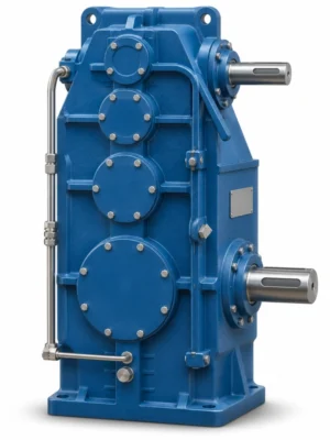
Audible noise is evidence to investigate, but fault location depends on whether the sound tracks speed, torque or the machine structure.
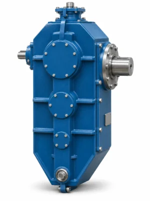
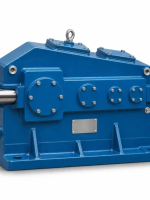
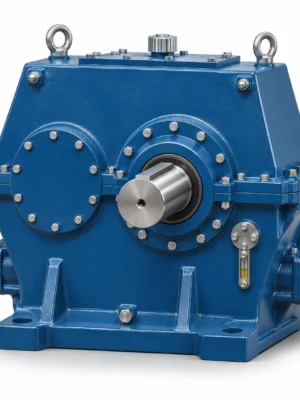
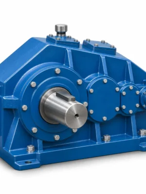
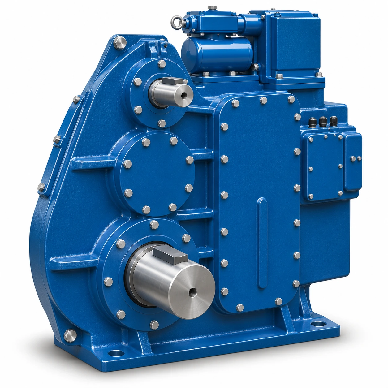
EP-J174GA-1000 Open-Gear Crane Reducer Assembly is a large horizontal cylindrical gear reducer arrangement associated with an external open-gear drive. The reference identifies an A1000 assembly and includes installation views, a selection code, ratio options and an illustrated connection region for the open gear. This is the type of reducer for which buyers often need to match a complete mechanical installation rather than purchase an interchangeable enclosed gearbox by ratio alone. Input speed, output connection, open-gear mesh position and the geometry of supporting equipment all affect the feasibility of a new or replacement unit.
Dedicated ratio codes
Nine numbered nominal transmission ratios are listed for the A1000 configuration.
Assembly arrangements
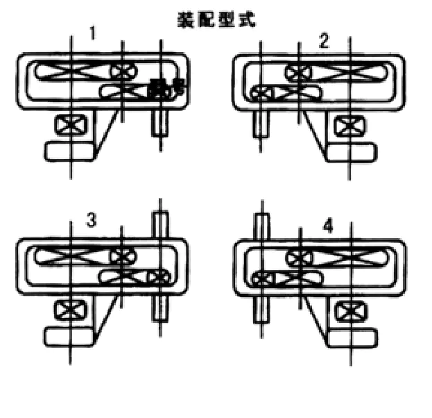
The order reference distinguishes four mounting assembly positions for the open-gear layout.
Heavy machinery duty
Open gear mesh and supporting structure require project-specific load and alignment assessment.
J174GA-1000 Gearbox Architecture and Gear-Drive Context
The general arrangement places the reducer housing alongside an output-side connection that is intended to work as part of the surrounding gear transmission. A technician selecting this family should separate the enclosed reduction from the larger open-gear mechanism. The ratio chosen inside the reducer changes shaft speed, while the external gear engagement may introduce additional reduction and reaction forces. The position of the toothed member or wheel matters because inaccurate mesh alignment can create uneven tooth contact, vibration and undesirable bearing loading in the supporting assembly.
The A1000 reference should not be mistaken for a universal heavy-duty gearbox with a freely interchangeable flange. Its dimensional illustration has specific centers, shaft projections, inspection locations and a side-mounted connecting region. On a replacement project, the correct task is to compare the old reducer and its associated gear train as an assembled system. This includes checking whether a field modification has changed the location of an open gear, motor, drum support or brake bracket since the original installation.
Reading the A1000 Selection and Order Code
The reference code is structured from the A1000 size, a Roman-numeral ratio code and an assembly-position number. An example of the format is A1000 III-2. A procurement request that states only the A1000 size does not settle the speed ratio or which side of the housing will face the driven member. Record the full designation, the old unit identification and any drawing revision when requesting a quote. The ratio-code Roman numerals should not be confused with the assembly-position numbers used later in the code.
| Code element | Example | Engineering role |
|---|---|---|
| Reference size | A1000 | Identifies the reducer assembly size reference |
| Ratio-code symbol | III | Selects a nominal reduction ratio using the Roman-numeral table |
| Assembly number | 2 | Specifies the assembly arrangement shown in the position sketches |
| Other drive requirements | Must be supplied separately | Motor, open-gear mating data, loads and foundation geometry |
Nominal Gear Ratios Available for J174GA-1000
The reference presents nine nominal transmission ratios, with a Roman numeral for each selection. These figures are part of the gearbox configuration and should not be multiplied or modified to claim a final crane movement speed until any external open gear or drum stage has been accounted for. If a customer identifies an installed ratio by watching a moving component, ask whether the measured output is on the reducer shaft or at the actual machine member. The distinction is important where an open-gear pair follows the enclosed reducer.
| Code | I | II | III | IV | V | VI | VII | VIII | IX |
|---|---|---|---|---|---|---|---|---|---|
| Nominal ratio | 48.57 | 40.17 | 31.5 | 23.34 | 20.49 | 15.75 | 12.64 | 10.35 | 8.23 |
Ratio values identify the referenced configurations only. Verify suitability for the required motor speed, output load and open-gear arrangement.
A buyer may initially ask for the most common or highest ratio, but a reducer choice should instead follow the measured input speed, target shaft rpm, available motor characteristics and duty schedule. Selecting a large ratio to reduce speed is not equivalent to approving the tooth stresses, bearing reactions or allowable start-up torque. Direction reversal can also affect the open gear mesh and the manner in which backlash is taken up in the surrounding drive.
Overall Dimensions and Equipment Envelope
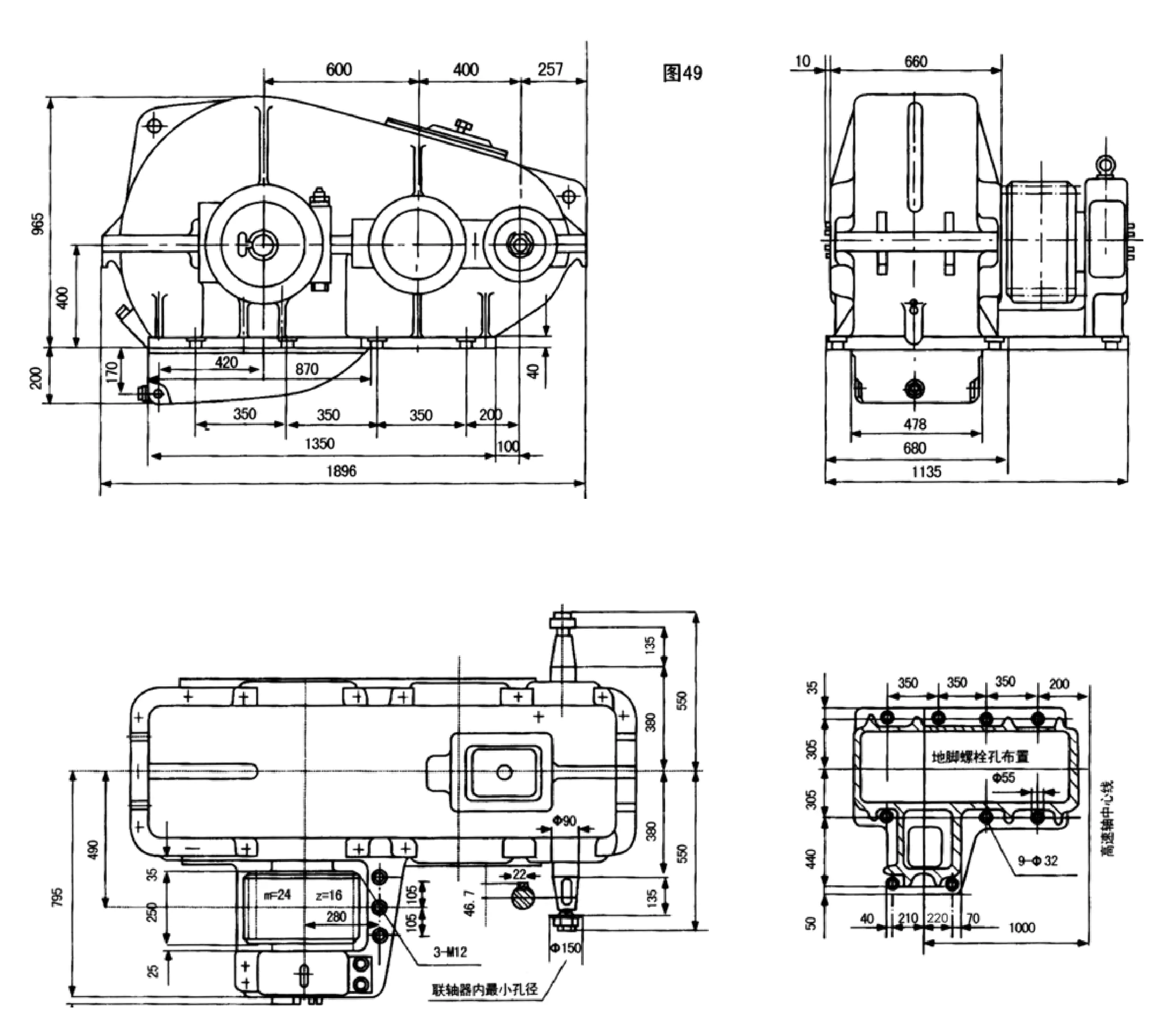
The dimensional drawing provides several orthogonal views. The longer elevation identifies a 1896 mm overall labeled span, a 965 mm vertical reference and repeated centers along the reducer body. Another view includes a 1135 mm cross-machine envelope reference. These values must be paired with the exact view and arrowheads before use: the dimensions are not a substitute for a full 3D interference check. The original machine may also have limited access near the coupling or outboard gear bearing, making a nominally similar reducer difficult to install.
| Drawing data | Reference value | Application in a matching review |
|---|---|---|
| A1000 size reference | A1000 | Use with the full ratio and assembly-position code |
| Long dimension in major view | 1896 mm | Compare the corresponding envelope direction with adjacent machine components |
| Vertical reference in major view | 965 mm | Check installed housing clearance and structural interfaces |
| Cross-machine dimension reference | 1135 mm | Check the corresponding orthogonal view and connected gear location |
| A1000 reference assembly weight | 2888 kg | Confirm actual shipping mass and lifting arrangement before handling |
Dimensions must be read together with their arrows and drawing datums. Reference figures do not certify a complete currently supplied configuration.
Assembly Positions and Connection-Side Orientation
Four numbered assembly sketches describe the relative placement of the gearbox-side and open-gear-side interfaces. The correct sketch depends on where the motor is located, which shaft faces the connecting gear and how the assembly will be installed relative to the crane equipment. A mirrored drawing is not an approved alternate orientation; it can affect shaft accessibility, the location of oil points and the direction in which a torque reaction enters the structure. Put the intended installation position on the RFQ drawing to avoid an ambiguous description such as left-hand or right-hand.
- Installation position: select the numbered sketch and mark it on the equipment drawing from a known viewing direction.
- Shaft connection: verify shaft height, projection, coupling design and the position of any open-gear component.
- Transmission chain: list the reducer ratio separately from any external open gear or chain stage.
- Clearance: compare the main housing envelope and the auxiliary connecting gear housing with the available steelwork space.
- Service access: leave room for covers, fasteners, guards and maintenance around the main gear-mesh region.
Open-Gear Interface and Bearing Reaction Loads
The open-gear side creates important engineering questions beyond enclosed reducer power. Gear tooth contact depends on center distance and alignment at the mating wheel; bearing loads depend on the gear force and the effective lever arm to each support. A connection drawing should identify gear module and tooth count, face width, pressure angle where relevant, and how the driven gear is supported outside the reducer. It is not sufficient to know that the output shaft has a diameter compatible with the existing component. The gear mesh can be geometrically wrong even when the shaft fits.
In inspection planning, prioritize the location of bearing support surfaces relative to the gear engagement plane. Record whether a coupling, key, spline or gear mounting transmits the torque and whether a retaining system provides axial location. When a worn open gear is being reused, ask for a condition assessment of its tooth profile and bearing seats. A replacement reducer alone cannot correct a badly misaligned or damaged mating member.
Hoisting or Travel Drive: Duty Definition
Crane drive mechanisms can be exposed to frequent acceleration, reversal and intermittent high load. The exact influence depends on whether the reducer drives a hoist, trolley travel, bridge travel or another mechanism. For a hoist, the overall brake and suspended-load control system must be assessed by the equipment designer; a gear reducer is not a substitute for braking and safety controls. For travel duty, the dynamic drive forces and wheel support conditions may be more important than suspended-load holding. State the actual application so that the engineering review is relevant.
Speed and ratio
Identify the motor rpm, the enclosed gearbox ratio and any external reduction to the driven wheel or drum.
Gear mesh loading
Report the driven gear pitch diameter, face width, alignment and support arrangement where available.
Wear and condition
Note tooth damage, side wear, coupling backlash or evidence of earlier alignment corrections.
J174GA-1000 Replacement Considerations
Replacing a reducer of this scale requires a documented installation sequence. The outboard connection should be checked before disassembly, because it can be difficult to reproduce the prior gear mesh position after the old unit is removed. Establish a controlled reference system from the machine framework, not from paint edges or rough casting surfaces. Take measurements of accessible shaft ends, gear centers and the mounting support while the machine is in a safe condition. Confirm how existing guards and service covers will fit after installation.
For comparison with more conventional enclosed products, the EP-QJY3 three-stage crane reducer illustrates a different gearbox family, and the Crane Gearboxes product overview provides wider structure choices. Their models are not presented as direct equivalents for the A1000 assembly, because the external gear interface and mounting layout may be fundamentally different.
What to Include with a J174GA-1000 Enquiry
A useful RFQ identifies whether the requested scope includes the reducer, mating open gear, coupling, brake interface or mounting elements. The price and manufacturing route depend on the actual assembly boundary. For project procurement, small quantities may be considered under a flexible MOQ policy, but extra technical review can be needed when the original machine data are incomplete. Freight planning should use the confirmed gross and packed weights rather than the assembly reference figure alone, especially where custom packaging is required.
- Full equipment general arrangement, model code and selected assembly-position number.
- Chosen Roman-numeral ratio code and the motor/input speed at rated operation.
- Open-gear mating specifications and shaft/gear connection drawing.
- Working mechanism, load cycle, reversals, target output speed and any known shock conditions.
- Quantity, destination/trade-term preference and required technical documentation.
Frequently Asked Questions
The following answers focus on the decisions that typically need to be resolved before an engineer can confirm a suitable crane gearbox configuration.
Review a J174GA-1000 Drive Assembly
Share the full A1000 code, ratio, assembly position, open-gear mating details and original crane drawing. Ever Power can discuss the reducer boundary and a configuration-specific quotation.