
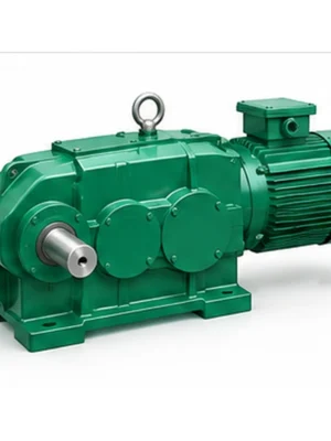
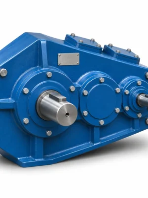
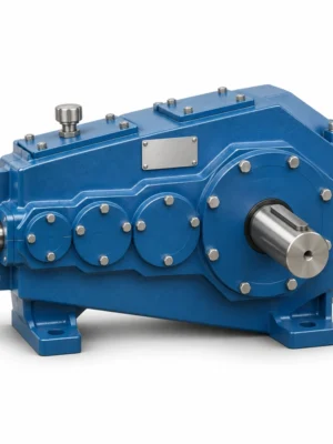
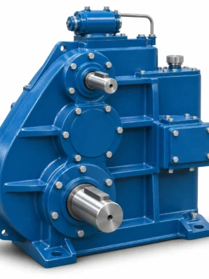
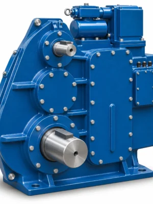
Audible noise is evidence to investigate, but fault location depends on whether the sound tracks speed, torque or the machine structure.
The EP-MBY Series Peripheral Drive Mill Gearbox is a single-stage reducer family for edge-drive arrangements in cement and coal milling equipment. The range is organized by nominal centre distance from MBY400 through MBY1100, with six nominal ratios from 4.0 to 7.1. Selection should start with transmitted power at the actual input speed, then move to shaft geometry, mounting arrangement, oil-station connection and the adjacent mill-drive components.
For a new installation or a replacement, matching a nominal model code alone is not sufficient. Verify the arrangement of the input and output shafts, available foundation space, shaft extension dimensions and lubrication connections against the machine drawing. The tables below bring the model family, input/output shaft details and reference power schedule together so an engineering enquiry can be prepared without losing the configuration context.
Model rangeMBY400–MBY1100
Nominal ratio options4.0 / 4.5 / 5.0 / 5.6 / 6.3 / 7.1
Reference input speeds600 / 740 / 1000 rpm
Mounting formsI–VI
LubricationDedicated oil-station arrangement
Drive applicationPeripheral / side drive of mills
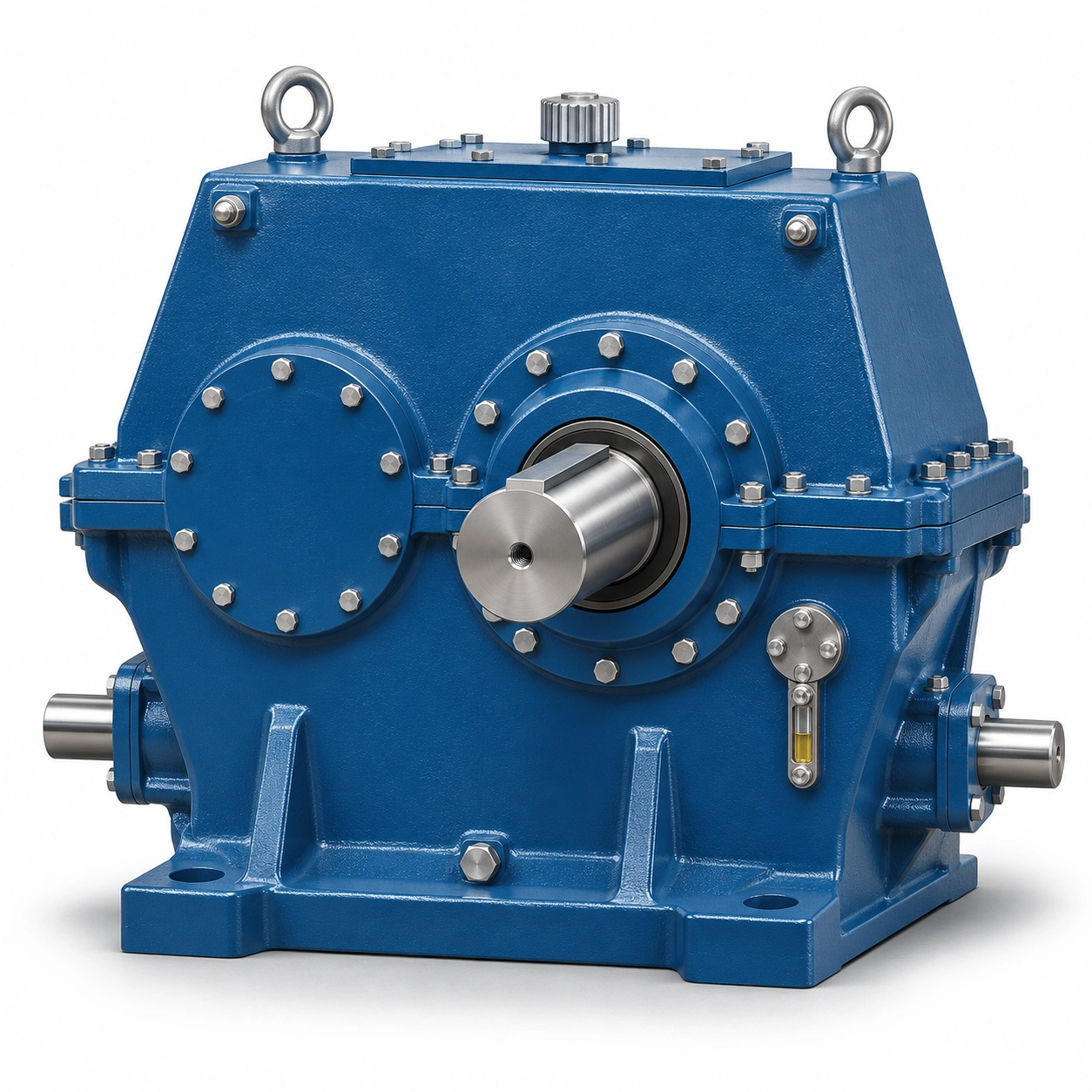
MBY400–MBY1100: Size Range and Physical Interfaces
An MBY designation includes a nominal centre-distance size. The basic size affects the bearing and shaft envelope, the foundation footprint, the reference gearbox mass and the associated lubrication-unit designation. Use the model table to narrow the available installation envelope before calculating the drive requirement.
The a column is the nominal centre-distance designation in millimetres. The drawing uses V, H, h, U, A, F, f, R, S, N, T, B and G for the housing and mounting-interface dimensions. The letters have engineering meaning only when read alongside the outline drawing; they are not interchangeable with similarly named dimensions on other gearbox series.
| Model | a (mm) | V (mm) | H (mm) | A (mm) | F (mm) | B (mm) | G (mm) | Oil station | Avg. mass (kg) |
|---|---|---|---|---|---|---|---|---|---|
| MBY400 | 400 | 1050 | 850 | 820 | 700 | 450 | 390 | XYZ25 | 1450 |
| MBY450 | 450 | 1160 | 950 | 900 | 780 | 510 | 450 | XYZ25 | 1950 |
| MBY500 | 500 | 1260 | 1050 | 980 | 840 | 550 | 480 | XYZ40 | 2600 |
| MBY560 | 560 | 1400 | 1170 | 1080 | 940 | 590 | 520 | XYZ40 | 3050 |
| MBY630 | 630 | 1670 | 1343 | 1320 | 1060 | 640 | 570 | XYZ63 | 3400 |
| MBY710 | 710 | 1750 | 1470 | 1350 | 1190 | 690 | 620 | XYZ63 | 4900 |
| MBY800 | 800 | 2030 | 1650 | 1480 | 1280 | 760 | 680 | XYZ63 | 5800 |
| MBY900 | 900 | 2163 | 1850 | 1650 | 1450 | 820 | 730 | XYZ63 | 8500 |
| MBY1000 | 1000 | 2380 | 2050 | 1820 | 1620 | 880 | 790 | XYZ125 | 9250 |
| MBY1100 | 1100 | 2570 | 2250 | 1980 | 1780 | 950 | 860 | XYZ125 | 11800 |
Reference envelope and average mass; mounting details and present supply configuration must be confirmed for the specific order.
For the smaller MBY400 and MBY450 cases, the f table field is not assigned a numerical value in the reference schedule. The MBY1000 and MBY1100 entries use F/3 for this location. Do not replace these entries with guessed dimensions when preparing a foundation drawing.
Gearbox Outline and Mounting Dimensions
The paired orthographic views show the central shaft locations, overall housing height, mounting-base spacing and connection points. On an operating mill, these positions affect alignment to the pinion-side drive train, foundation-bolt layout, coupling clearance and the space required to remove shaft-end components. The view should be checked together with an installation survey rather than scaled from the picture.
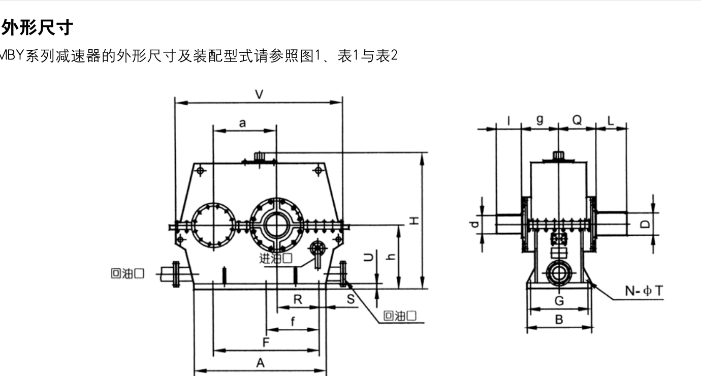
Complete reference envelope dimensions
| Model | a | V | H | h | U | A | F | f | R | S | N | T | B | G | Oil unit | Avg kg |
|---|---|---|---|---|---|---|---|---|---|---|---|---|---|---|---|---|
| MBY400 | 400 | 1050 | 850 | 400 | 50 | 820 | 700 | / | 275 | 60 | 4 | 27 | 450 | 390 | XYZ25 | 1450 |
| MBY450 | 450 | 1160 | 950 | 450 | 50 | 900 | 780 | / | 305 | 60 | 4 | 27 | 510 | 450 | XYZ25 | 1950 |
| MBY500 | 500 | 1260 | 1050 | 500 | 50 | 980 | 840 | 420 | 330 | 70 | 6 | 33 | 550 | 480 | XYZ40 | 2600 |
| MBY560 | 560 | 1400 | 1170 | 560 | 55 | 1080 | 940 | 470 | 370 | 70 | 6 | 33 | 590 | 520 | XYZ40 | 3050 |
| MBY630 | 630 | 1670 | 1343 | 630 | 55 | 1320 | 1060 | 530 | 420 | 70 | 6 | 39 | 640 | 570 | XYZ63 | 3400 |
| MBY710 | 710 | 1750 | 1470 | 710 | 55 | 1350 | 1190 | 595 | 470 | 80 | 6 | 39 | 690 | 620 | XYZ63 | 4900 |
| MBY800 | 800 | 2030 | 1650 | 800 | 70 | 1480 | 1280 | 640 | 500 | 100 | 6 | 39 | 760 | 680 | XYZ63 | 5800 |
| MBY900 | 900 | 2163 | 1850 | 900 | 70 | 1650 | 1450 | 725 | 575 | 100 | 6 | 45 | 820 | 730 | XYZ63 | 8500 |
| MBY1000 | 1000 | 2380 | 2050 | 1000 | 90 | 1820 | 1620 | F/3 | 630 | 100 | 8 | 45 | 880 | 790 | XYZ125 | 9250 |
| MBY1100 | 1100 | 2570 | 2250 | 1100 | 90 | 1980 | 1780 | F/3 | 695 | 100 | 8 | 45 | 950 | 860 | XYZ125 | 11800 |
All linear dimensions are in millimetres. “/” means not specified as a number in the reference table; “F/3” retains the specified formula.
Installation priority Confirm the dimension drawing revision, shaft-axis heights, foundation hold-down pattern and centreline alignment before fabrication or retrofit. The tabulated mass is a reference for lifting and supporting calculations, not a substitute for an approved lifting plan.
Six MBY Gearbox Mounting Arrangements (I–VI)
The MBY design family identifies six assembly arrangements, marked I, II, III, IV, V and VI. These small diagrams distinguish the relative shaft-extension and mounting positions. The arrangement code belongs in the purchase specification because the wrong handedness or extension location can prevent installation even when the centre distance and nominal ratio are correct.
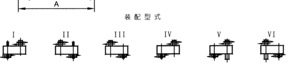
When an existing mill gearbox is being replaced, record which end faces the drive motor, the location of the output pinion coupling, the accessible maintenance side, and the direction in which shaft ends must project. Reversibility of the gear train does not by itself establish that every mounting form suits the same equipment envelope.
Input and Output Shaft Dimensions
Shaft diameters and extension lengths vary by gearbox size and by nominal ratio. The reference shaft schedule groups input shafts into four ratio bands: i = 4.0, i = 4.5–5.0, i = 5.6–6.3 and i = 7.1. The output extension is identified separately as Q, D and L. These are nominal schedule dimensions; confirm fits, keyway/tolerance details and coupling design on the approval drawing.
| Model | i=4 g | i=4 d | i=4 l | i=4.5–5 g | i=4.5–5 d | i=4.5–5 l | i=5.6–6.3 g | i=5.6–6.3 d | i=5.6–6.3 l | i=7.1 g | i=7.1 d | i=7.1 l | Output Q | Output D | Output L |
|---|---|---|---|---|---|---|---|---|---|---|---|---|---|---|---|
| MBY400 | 270 | 120 | 200 | 270 | 100 | 200 | 270 | 90 | 180 | 270 | 80 | 140 | 270 | 160 | 200 |
| MBY450 | 300 | 120 | 220 | 300 | 120 | 200 | 300 | 100 | 180 | 300 | 90 | 160 | 300 | 180 | 220 |
| MBY500 | 320 | 140 | 240 | 320 | 140 | 200 | 320 | 110 | 180 | 320 | 100 | 160 | 320 | 180 | 240 |
| MBY560 | 340 | 160 | 250 | 340 | 160 | 200 | 340 | 120 | 200 | 340 | 110 | 180 | 340 | 200 | 260 |
| MBY630 | 370 | 180 | 250 | 370 | 160 | 230 | 370 | 130 | 200 | 370 | 120 | 180 | 370 | 220 | 300 |
| MBY710 | 390 | 200 | 280 | 390 | 160 | 250 | 390 | 150 | 220 | 390 | 140 | 200 | 390 | 260 | 340 |
| MBY800 | 425 | 220 | 300 | 425 | 180 | 260 | 425 | 180 | 240 | 425 | 160 | 200 | 425 | 300 | 380 |
| MBY900 | 455 | 240 | 340 | 455 | 200 | 260 | 455 | 180 | 260 | 455 | 180 | 220 | 455 | 300 | 400 |
| MBY1000 | 485 | 260 | 380 | 485 | 240 | 280 | 485 | 200 | 280 | 485 | 200 | 250 | 485 | 320 | 420 |
| MBY1100 | 520 | 280 | 400 | 520 | 260 | 300 | 520 | 220 | 300 | 520 | 220 | 280 | 520 | 360 | 440 |
Dimension values in mm. Letter definitions follow the corresponding shaft-extension and outline drawings; the required coupling connection must be specified individually.
What to check at the coupling
- Input end: confirm the motor/coupling arrangement and input-shaft diameter, extension length, keyway and permitted installation position.
- Output end: check the mating connection, overhung loading from adjacent components, and the shaft envelope around guards and bearings.
- Axial positions: compare the distance between gearbox bearing housing and external connection plane; a correct nominal diameter does not guarantee installation fit.
- Drawing control: provide a dimensioned existing gearbox sketch or approved model drawing whenever replacing an old drive.
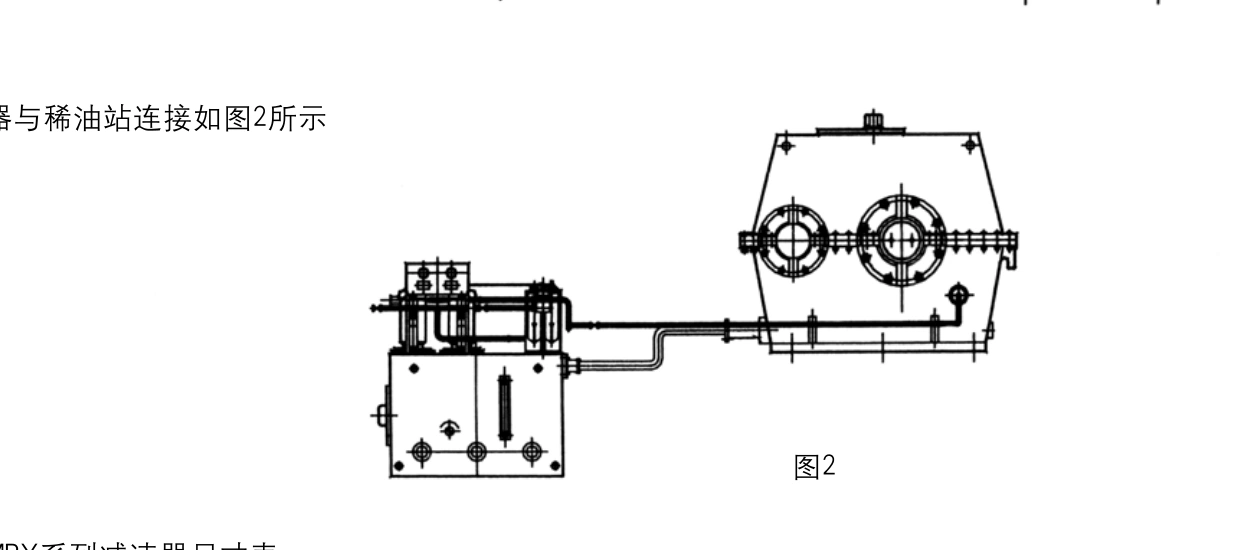
Lubrication Oil Station and Connection Arrangement
The MBY peripheral-drive reference shows a dedicated oil-station arrangement connected by piping to the gearbox. Oil-station selection is part of the transmission system design, not an afterthought: start-up permissives, oil-flow monitoring, piping routing, contamination control, operating temperature and service access may all affect the installation. The exact oil unit supplied, accessories and control interface depend on the confirmed project scope.
| Gearbox model | Oil-station reference |
|---|---|
| MBY400 | XYZ25 |
| MBY450 | XYZ25 |
| MBY500 | XYZ40 |
| MBY560 | XYZ40 |
| MBY630 | XYZ63 |
| MBY710 | XYZ63 |
| MBY800 | XYZ63 |
| MBY900 | XYZ63 |
| MBY1000 | XYZ125 |
| MBY1100 | XYZ125 |
Oil-unit references follow the model schedule. Verify the ordered oil station, pump and cooling arrangement with the final equipment specification.
Commissioning and operating-temperature considerations
The MBY design guidance includes reversible operation, a gear pitch-line speed limit of 20 m/s and a reference ambient range of −40°C to +40°C. It also calls for lubricant warm-up before start-up below 0°C, and for additional cooling measures above 40°C. These are configuration-specific reference conditions: they must be checked against the actual oil viscosity, bearing arrangement, thermal loading, start/stop frequency and local environment.
During the quotation stage, specify whether the oil station is part of the requested supply, whether the site already has centralized lubrication, and whether the electrical controls need flow, pressure or temperature feedback. Confirmation of the safe start sequence and lubrication interlocks belongs in the final engineering documents.
MBY Gear Ratios and Reference Power Ratings
The nominal ratio choices are 4.0, 4.5, 5.0, 5.6, 6.3 and 7.1. For a given size, the reference transmitted-power schedule changes with both ratio and input speed. Compare the row for the desired input speed first; do not extrapolate a rating from a faster speed or a different ratio without an engineering calculation.
The table below presents the reference power schedule in kW for each MBY size at 600, 740 and 1000 rpm input. It is a selection reference, not a current certified rating for a purchase order. A final duty review must account for shock load, service factor, thermal conditions, start-up torque and any atypical operating cycle.
| Ratio i | Input rpm | MBY400 | MBY450 | MBY500 | MBY560 | MBY630 | MBY710 | MBY800 | MBY900 | MBY1000 | MBY1100 |
|---|---|---|---|---|---|---|---|---|---|---|---|
| 4.0 | 1000 | 496 | 688 | 892 | 1235 | 1710 | 2380 | 3160 | 4455 | 5890 | 7600 |
| 4.0 | 740 | 368 | 510 | 656 | 915 | 1270 | 1764 | 2340 | 3300 | 4365 | 5630 |
| 4.0 | 600 | 300 | 410 | 530 | 740 | 1030 | 1430 | 1890 | 2670 | 3500 | 4560 |
| 4.5 | 1000 | 418 | 580 | 741 | 1036 | 1445 | 2011 | 2670 | 3766 | 4960 | 6430 |
| 4.5 | 740 | 310 | 430 | 549 | 768 | 1070 | 1490 | 1980 | 2790 | 3676 | 4765 |
| 4.5 | 600 | 250 | 350 | 445 | 620 | 860 | 1200 | 1600 | 2250 | 2970 | 3850 |
| 5.0 | 1000 | 357 | 510 | 634 | 886 | 1240 | 1710 | 2280 | 3226 | 4250 | 5485 |
| 5.0 | 740 | 265 | 380 | 470 | 657 | 918 | 1270 | 1690 | 2392 | 3150 | 4063 |
| 5.0 | 600 | 215 | 308 | 380 | 530 | 740 | 1030 | 1370 | 1930 | 2550 | 3290 |
| 5.6 | 1000 | 300 | 418 | 534 | 745 | 1040 | 1445 | 1917 | 2700 | 3585 | 4540 |
| 5.6 | 740 | 223 | 310 | 396 | 552 | 770 | 1070 | 1420 | 2000 | 2656 | 3363 |
| 5.6 | 600 | 180 | 250 | 320 | 450 | 620 | 860 | 1150 | 1620 | 2150 | 2720 |
| 6.3 | 1000 | 248 | 350 | 440 | 620 | 864 | 1200 | 1590 | 2250 | 2956 | 3816 |
| 6.3 | 740 | 184 | 260 | 327 | 460 | 640 | 890 | 1180 | 1670 | 2190 | 2827 |
| 6.3 | 600 | 150 | 210 | 265 | 370 | 520 | 720 | 950 | 1350 | 1770 | 2280 |
| 7.1 | 1000 | 200 | 290 | 367 | 513 | 702 | 990 | 1360 | 1860 | 2400 | 3140 |
| 7.1 | 740 | 150 | 215 | 272 | 380 | 520 | 734 | 1010 | 1380 | 1800 | 2325 |
| 7.1 | 600 | 120 | 175 | 220 | 307 | 420 | 590 | 800 | 1100 | 1460 | 1880 |
Reference power (kW). Values relate to the stated ratio and input speed; final permitted power requires project-specific confirmation.
How ratio selection affects the drive
A lower nominal ratio produces a higher nominal output speed at the same input rpm, while a higher ratio produces a lower output speed. This is a kinematic relationship rather than a guarantee of delivered mill torque. For initial sizing, calculate nominal output speed as input rpm ÷ selected nominal ratio; then obtain the actual ratio and efficiency of the ordered gearbox to complete the torque and speed calculation.
The mating drive components must be evaluated as a system. A gearbox may satisfy the reference power table and still be unsuitable if the external shaft connection, pinion support loads, lubricant supply, mounting direction or emergency-stop duty differs from the proposed configuration.
Worked Example: Selecting an MBY710 Gearbox
Consider a mill-drive project requiring 1000 kW motor power, 1000 rpm input speed and a nominal ratio of 6.3. The MBY710 reference row at i = 6.3 and 1000 rpm gives 1200 kW. The example order description is MBY710-6.3-IV-L, with an XYZ63 oil-station reference.
| Selection variable | Illustrative project value |
|---|---|
| Motor input power | 1000 kW |
| Input speed | 1000 rpm |
| Nominal ratio | 6.3 |
| Selected reference size | MBY710 |
| Reference transmitted-power entry | 1200 kW |
| Assembly specification | MBY710-6.3-IV-L |
| Oil-station reference | XYZ63 |
This is an example of reading the reference selection table, not a guarantee of suitability or availability for a live project.
For a real order, confirm the intended service factor, start-up and peak torque, mill load profile, site temperature, oil station and the final outline drawing. The IV-L suffix is an installation identifier that must be matched to the approved arrangement drawing rather than inferred from the product name.
Typical Application and Drive-System Integration
The MBY series is relevant to edge-drive arrangements of cement grinding mills and coal mills. These applications involve a large rotating process machine with defined operating speed, scheduled starts and stops, and a drive train that must hold alignment under changing load. The gearbox can be considered as one element in a broader system that may include the motor, flexible coupling, pinion drive connection, foundation and a separate oil station.
Cement mill peripheral drive
In a cement-mill arrangement, purchase decisions should focus on the gearbox ratio that meets the expected drum-drive speed, the transmitted power after duty factors, the footprint and shaft geometry that fit the existing mill train, and oil-station capacity. A replacement enquiry should include both the old gearbox model and the equipment-side coupling or pinion connection drawing.
Coal mill and other edge-drive applications
For coal-mill service, the system specification must also address the actual duty cycle, contamination environment, start-up sequence, lubrication monitoring and plant maintenance constraints. Suitability should be evaluated from the machine operating data; the application name alone does not establish an appropriate gearbox rating or installation form.
Replacement and Retrofit Measurement Checklist
Retrofitting a mill drive is a mechanical-interface project as much as a gearbox selection. The reference drawings can help organize the comparison, but they cannot replace measurements from the installed equipment. Before ordering a replacement reducer, provide the old identification plate and dimensional details wherever possible.
- Machine and drive data: mill type, motor rating, input rpm, existing reduction ratio, normal load and peak/start load.
- Housing and foundation: overall envelope, centreline elevation, hold-down pattern, base support, lifting and service clearances.
- Shaft arrangements: input/output end orientation, existing coupling or pinion interface, shaft diameters, extensions and fit drawings.
- Lubrication: existing oil-station type, pipe locations, flow/pressure provisions, cooling connections and control-interlock expectations.
- Installation constraints: permissible stop duration, direction of rotation, site ambient range, guarding, access and preferred shipping split.
- Commercial scope: required quantity, drawings and approvals, whether the oil station and coupling are included, and the required delivery destination.
Replacement matching A nominal MBY frame size or ratio is an initial identification reference, not proof of drop-in interchangeability. Confirm all critical interfaces and performance requirements before release.
Procurement, Documentation and Inspection Scope
An effective MBY enquiry separates the gearbox unit from its accessories. State clearly whether the package should include the dedicated lubrication unit, piping or flange interfaces, coupling components, mounting hardware, documentation and inspection results. Without a defined scope, two quotations for the same size may not describe equivalent equipment.
For technical approval, request an outline drawing with installation datum and shaft details, a specification sheet for the selected ratio and service conditions, lubrication-system connection requirements, and the inspection/test documentation agreed for the order. Materials, tooth accuracy class and treatment requirements should be confirmed for the actual design rather than transferred automatically from a generic series description.
For project scheduling, the delivery date depends on confirmed dimensions, manufacturing scope, drawing approvals and the number of units. Indicate when the unit must be ready for installation and whether any critical downtime constraint applies. If an original gearbox drawing is missing, photographs and measured interfaces can support an initial engineering review but should not be treated as a complete dimension-controlled record.
Frequently Asked Questions
What is the difference between MBY400 and MBY1100?
The numbers identify different nominal centre-distance sizes and associated housing, shaft, average-mass and lubrication-reference dimensions. MBY400 uses a 400 mm nominal centre-distance designation; MBY1100 uses 1100 mm. Choose a size by both mechanical interface and power duty, not by the number alone.
Which MBY reduction ratios can be evaluated?
The available nominal ratios in this series reference are 4.0, 4.5, 5.0, 5.6, 6.3 and 7.1. Use the selected ratio with the applicable 600, 740 or 1000 rpm row in the power schedule. Confirm the actual ordered gear ratio and allowable power with engineering.
Does every MBY gearbox include an oil station?
An external lubrication station is part of the illustrated design arrangement, and the model schedule gives XYZ25, XYZ40, XYZ63 or XYZ125 reference designations by size. Whether the station, accessories, instrumentation and piping are included in the quotation must be stated separately.
How do I choose mounting arrangement I, II, III, IV, V or VI?
Compare the six arrangement sketches with the actual machine layout, input/output shaft extension direction and access requirements. Record the arrangement code and verify the final approved outline before ordering. The codes are not simply alternative labels for the same shaft orientation.
What information is needed to replace an existing mill gearbox?
Send the old gearbox nameplate, motor power and speed, nominal ratio, operating load, outline drawing or shaft dimensions, foundation layout, oil-system information and requested quantity. Add photos of the coupling, pinion interface and available service space if drawings are incomplete.
Request an EP-MBY Peripheral Drive Gearbox Quote
To discuss an MBY400–MBY1100 gearbox, send the target model or existing gearbox reference, power and speed, ratio, mounting type, shaft dimensions, oil-system requirements, installation drawing and quantity. A complete enquiry helps determine whether the requested configuration can be assessed without ambiguity.
Discuss your MBY mill-drive project
Share the mill-drive duty, interface drawing and oil-station scope to request a configuration review and quotation.
Request a Gearbox Quotesales@netherlandsdrive.com
Explore additional gearbox options on the NetherlandsDrive homepage, or send dimensional questions through the contact page.