Audible noise is evidence to investigate, but fault location depends on whether the sound tracks speed, torque or the machine structure.
Helical Gearbox Noise Diagnosis by Speed and Load
read more

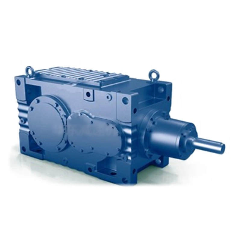
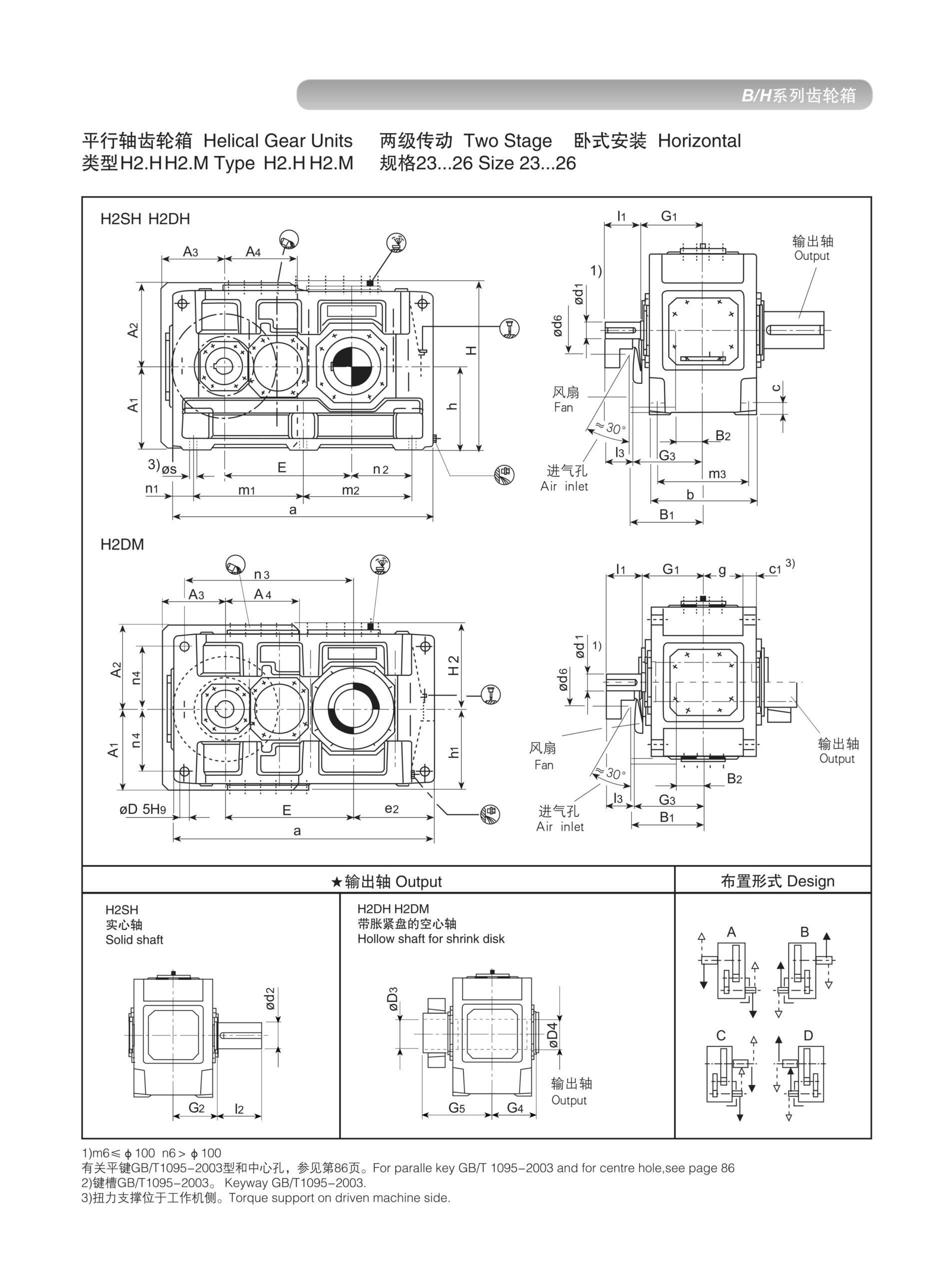
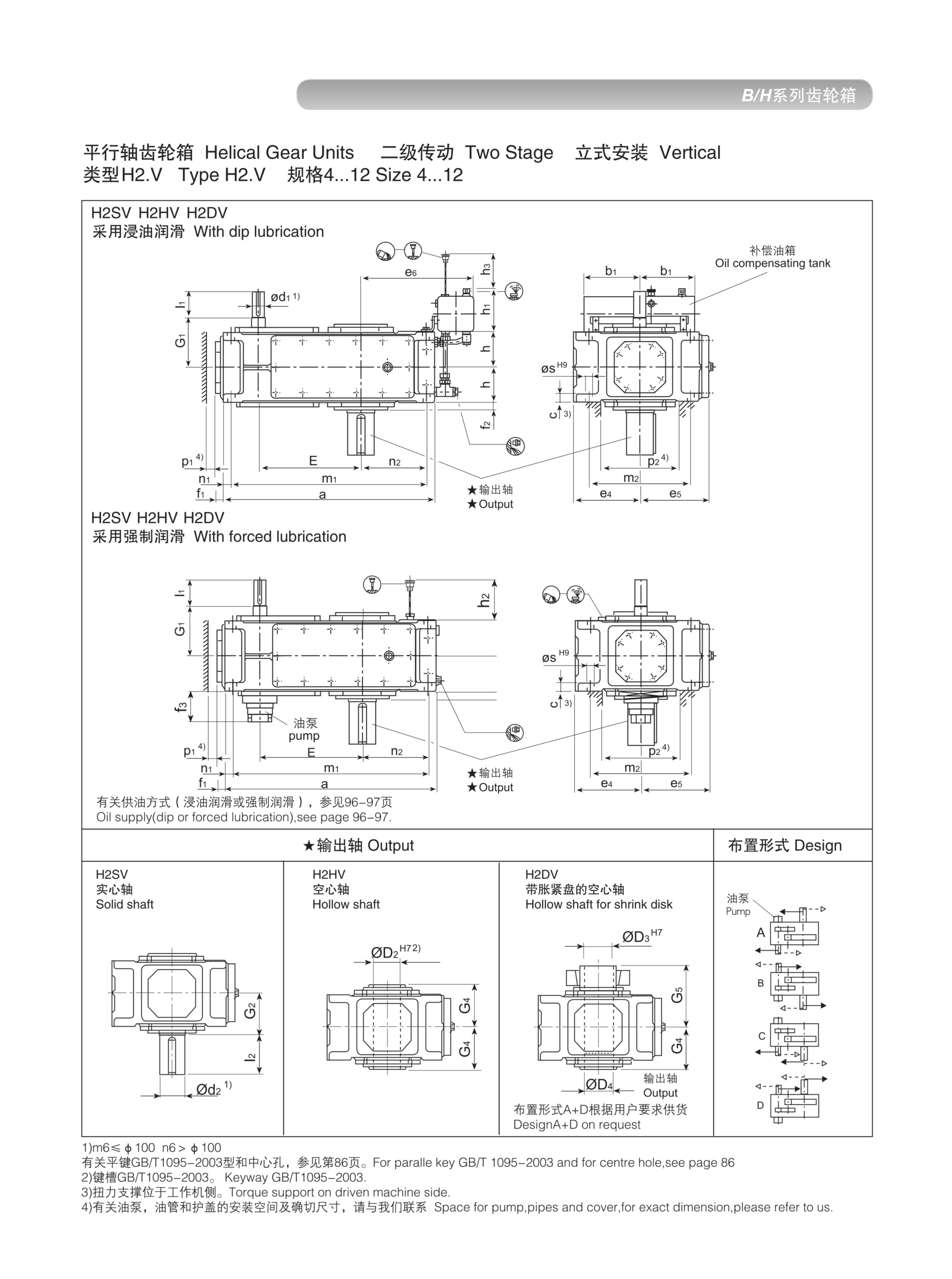
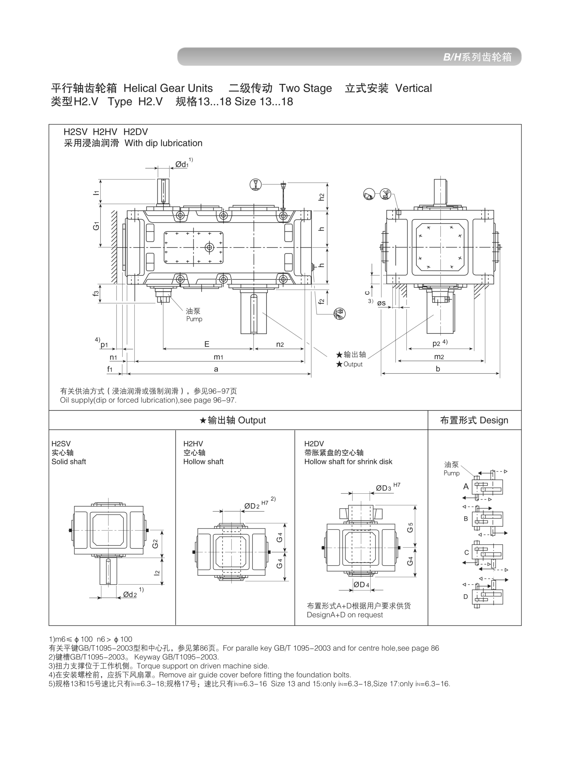
EP-H2 is a two-stage helical inline gearbox providing speed ratios up to 45:1 and nominal output torques to 90 kNm across sizes 4–26. The standard choice for medium-to-heavy industrial drives in process plants, conveyor systems, and continuous-duty applications.
MOQ: Flexible. Minimum order value USD 1,500; mixed orders and trial quantities welcome.
Two-stage parallel-shaft helical reducer — higher ratios, greater torque capacity, same in-line geometry. Up to 90 kNm across sizes 4–26.
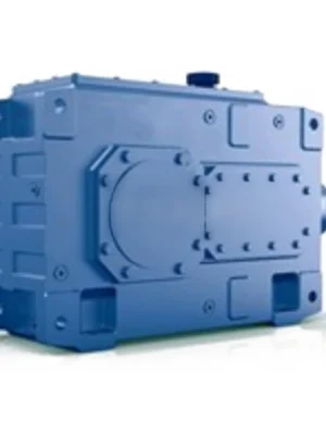
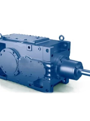
The EP-H2 is the second tier of the Ever Power HB helical inline gearbox series — a two-stage parallel-shaft unit that extends the ratio and torque capability of the H1 architecture without departing from the proven in-line shaft arrangement. By adding a second helical mesh, the H2 achieves speed ratios up to approximately 45:1 within a single compact housing, covering the majority of industrial speed-reduction requirements in one unit.
Where the H1 targets applications needing direct, efficient single-stage reduction, the EP-H2 is designed for the wider band of process industry drives where motor speeds of 1450–1500 rpm must be reduced to 30–250 rpm output speeds efficiently and reliably. Sizes 4 through 26 deliver nominal output torques from approximately 0.25 kNm at the smallest frame up to 90 kNm at Size 26 — making the H2 the go-to unit for medium-to-heavy industrial duty cycles.
Three dimensional groups cover different size sub-ranges (sizes 4–12, 13–22, and 23–26), each with corresponding horizontal and vertical dimensional drawings to support foundation design and installation planning.
Achieving gear ratios above about 6:1 from a single helical stage requires either very small pinions (reducing torque density) or very large gear wheels (increasing cost and envelope). Two-stage units solve this cleanly: each stage handles a moderate ratio around 2.5–6.3:1, and the combination produces the product ratio (e.g., 4:1 × 6.3:1 = 25:1) within a housing that is only modestly larger than the equivalent single-stage torque class.
This architecture also distributes the total transmitted load across two gear pairs, allowing each pair to be lighter and more easily manufactured to precise tolerances. The result is a two-stage unit with lower tooth loads per stage, better heat management, and more consistent noise levels than a single-stage unit working at the same overall ratio and torque.
An important efficiency note: two-stage efficiency is approximately 96–97% (two meshes at ~98% each), compared with the H1's 98%+ single-stage value. For very high-cycle drives where power cost dominates lifecycle cost, this difference should be factored into the selection. For the great majority of industrial applications, the H2's higher ratio versatility far outweighs the marginal efficiency difference.
EP-H2 spans sizes 4 through 26, with three dimensional groups. Nominal output torques and typical ratio ranges:
| Size | Nom. Output Torque (kNm) | Max Input Speed (rpm) | Ratio Range (i) | Representative Applications |
|---|---|---|---|---|
| 4 | 0.25 | ≤1500 | 6.3–40 | Auxiliary drives, small feeders |
| 6 | 0.55 | ≤1500 | 6.3–40 | Packaging, conveyors |
| 8 | 1.20 | ≤1500 | 6.3–40 | Process agitators |
| 10 | 2.40 | ≤1500 | 6.3–40 | Screw conveyors, feeders |
| 13 | 5.00 | ≤1500 | 6.3–45 | Heavy conveyors, mixers |
| 16 | 10.0 | ≤1500 | 6.3–45 | Bucket elevators, heavy agitators |
| 19 | 22.0 | ≤1000 | 6.3–45 | Mill drives, heavy process fans |
| 22 | 50.0 | ≤750 | 6.3–45 | Large mixers, slow conveyors |
| 26 | 90.0 | ≤600 | 6.3–45 | Heavy equipment, industrial drives |
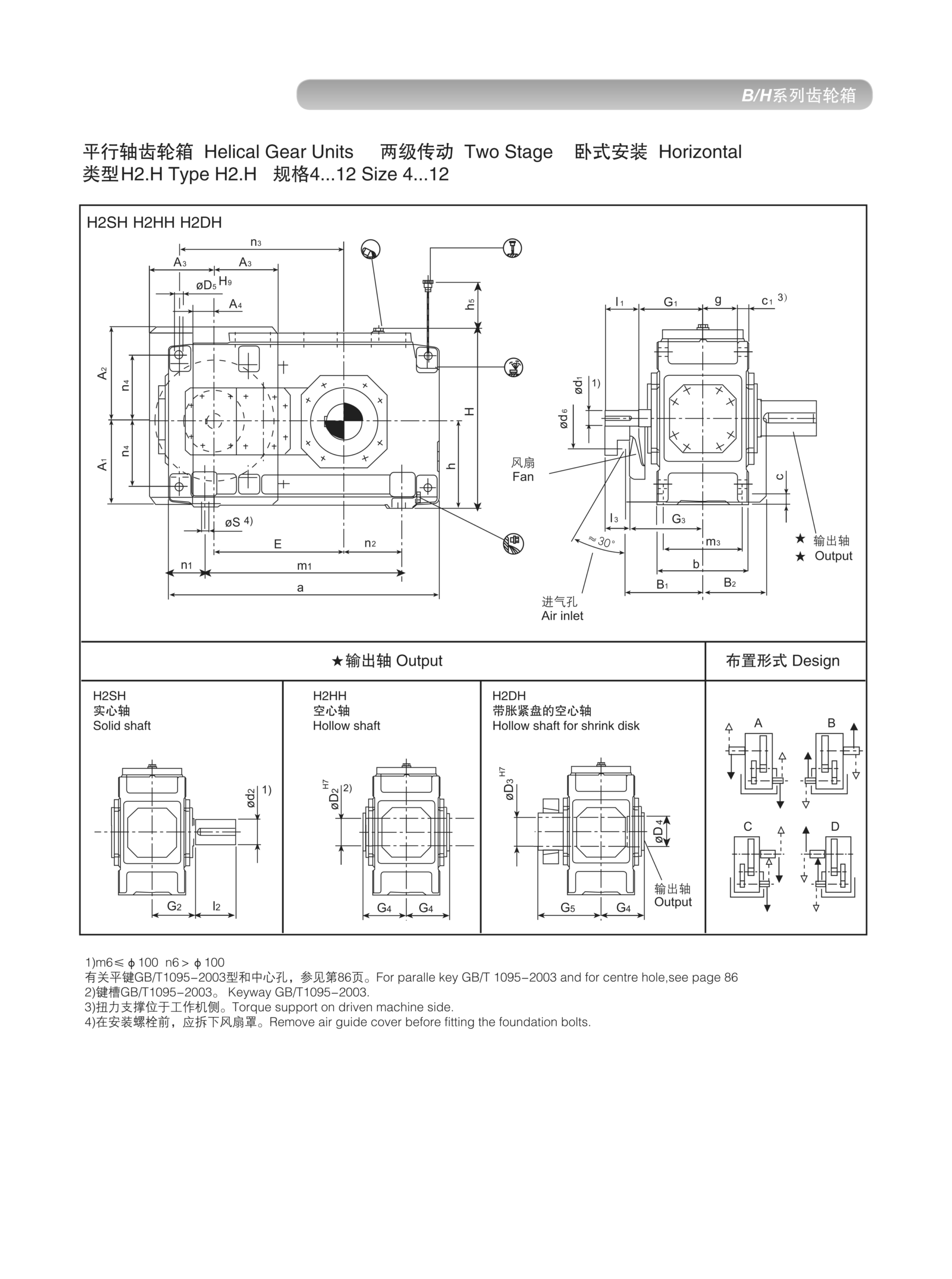
EP-H2 Horizontal Dimension Drawing — Sizes 4–12
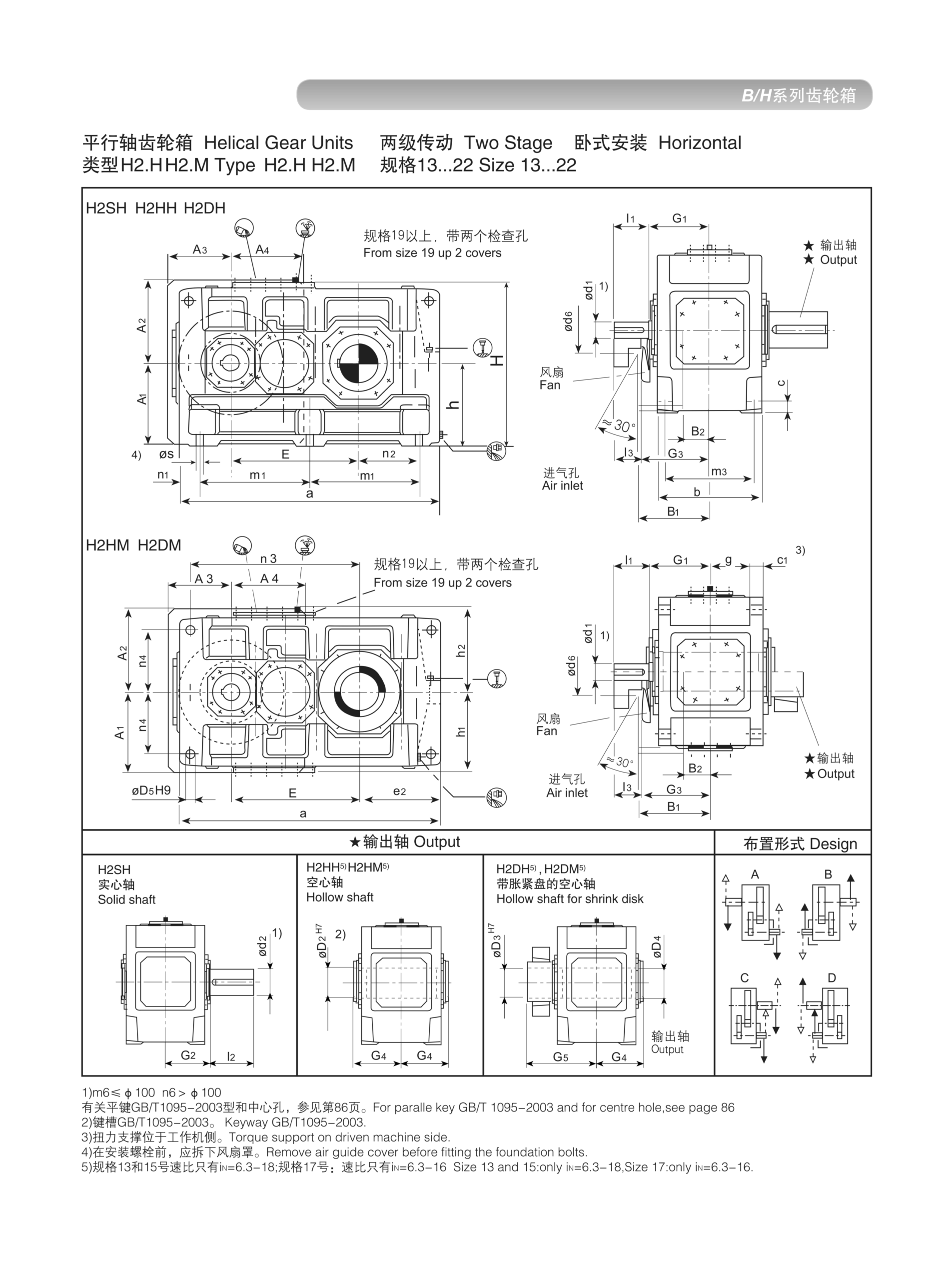
EP-H2 Horizontal Dimension Drawing — Sizes 13–22
EP-H2 Vertical Dimension Drawing — Sizes 4–12
Apply the appropriate service factor before size selection. Contact our team for specific ratio availability per size.
EP-H2 dimensional drawings are grouped into three sub-ranges to manage drawing complexity. All drawings show envelope dimensions, shaft extensions, foot and flange bolt patterns, and oil level/drain/breather port locations.
| Size Group | Notes |
|---|---|
| Sizes 4–12 | Smallest frame group; compact footprint for space-limited OEM installations |
| Sizes 13–22 | Mid-range; covers the majority of standard process plant drives |
| Sizes 23–26 | Largest H2 frames; heavy industrial and mining support equipment |
Horizontal and vertical dimension drawings are provided separately, as shaft seal positions, oil level marks, and breather locations differ between orientations. Always specify the mounting orientation at the time of order so the correct internal lubrication configuration is supplied.
Two sets of carburised and ground helical gear pairs, each operating at moderate tooth loads. Load is distributed across two stages, reducing heat generation and extending contact fatigue life compared with a single-stage unit at equivalent ratio.
The intermediate shaft connects the two gear stages within the housing. Precision-machined and carried on anti-friction bearings, it maintains exact centre distances and eliminates the alignment dependencies of stacked single-stage units.
Sizes 4–12, 13–22, and 23–26 each have their own dimensional envelopes, allowing optimal housing proportions for each frame class rather than over-sizing the small frames to match the largest.
At higher ratios the H2 can generate more internal heat than an H1 at comparable power. The ribbed housing is designed with sufficient surface area to reject rated thermal load at standard ambient temperatures. For high-ambient or enclosed installations, specify the optional cooling fan kit.
HSH, HHH, HDH, HHM, HDM for horizontal; HSV, HHV, HDV for vertical. Hollow-bore variants enable direct shaft mounting to conveyor head pulleys, mixer shafts, and drum drives without separate coupling assemblies.
Two-stage ratios from approximately 6.3:1 to 45:1 cover most industrial speed-reduction requirements in a single catalogue unit. Custom ratios outside this range are available on request.
The EP-H2's combination of two-stage ratio depth and broad torque coverage makes it one of the most widely specified gearboxes in the HB series:
| Industry | Application | Key Requirement Met |
|---|---|---|
| Mining & Quarrying | Conveyor drives, crusher feed | High torque, heavy shock tolerance |
| Cement & Minerals | Bucket elevators, kiln auxiliaries | High ratio, continuous duty |
| Chemical | Reactor agitators, pump drives | Sealed housing, long MTBF |
| Pulp & Paper | Slow rolls, felt drives | Precision ratio, low vibration |
| Food Processing | Mixer drives, augers, conveyors | Hygienic lubricant option |
| Water & Wastewater | Sludge mixers, aerators, clarifiers | Vertical mounting, sealed shafts |
Ratio Selection. For two-stage H2 units, specify the exact output speed or ratio required. Our standard catalogue covers ratios from 6.3:1 to 45:1 in preferred number series steps. Non-standard ratios are achievable with extended lead times.
Thermal Derating. At ambient temperatures above 40°C, or in installations with restricted air circulation, the continuous power rating must be derated. Our technical data tables provide derating curves — or contact us with your ambient conditions for a confirmed thermal rating.
Vertical Mounting Precautions. Vertical installations require specific lubrication configuration to ensure all bearings and gear meshes receive adequate oil supply. The unit must be ordered specifying vertical orientation; retrofitting a horizontal unit to vertical without internal modification will result in inadequate lubrication of the upper stage bearings.
Submit your application data for a complete size, ratio, and mounting recommendation from our engineering team.
Share your speed ratio, output torque, and mounting orientation. We will confirm the correct size and provide a competitive quotation within one business day.
Audible noise is evidence to investigate, but fault location depends on whether the sound tracks speed, torque or the machine structure.
Flexible couplings accommodate limited relative movement, but poor shaft alignment still affects bearings and seals.
Oil observed on a housing may have traveled from a vent, joint or shaft seal; finding the first wet point is essential.