Audible noise is evidence to investigate, but fault location depends on whether the sound tracks speed, torque or the machine structure.
Helical Gearbox Noise Diagnosis by Speed and Load
read more

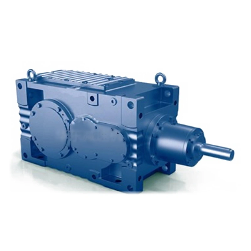
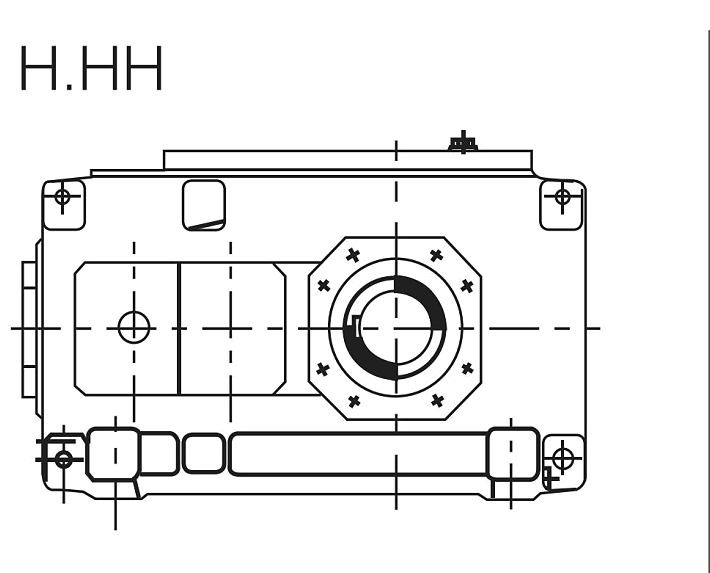
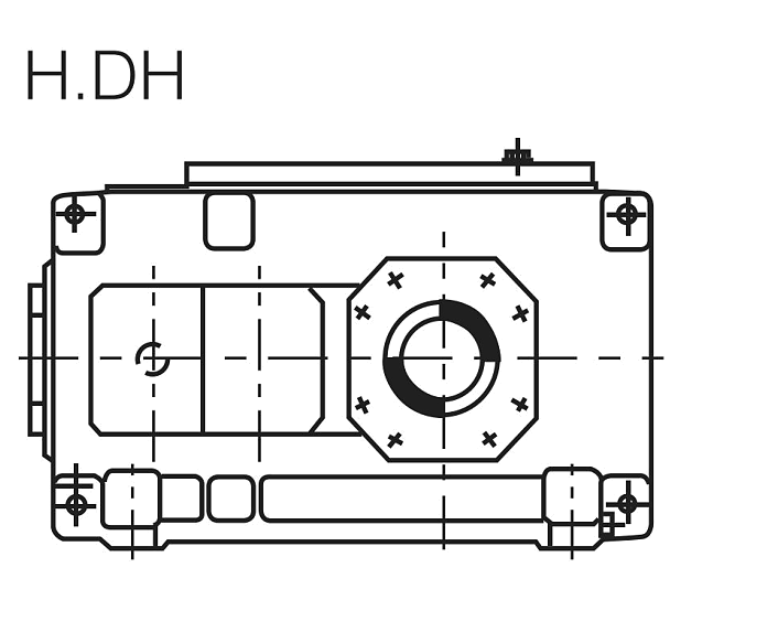
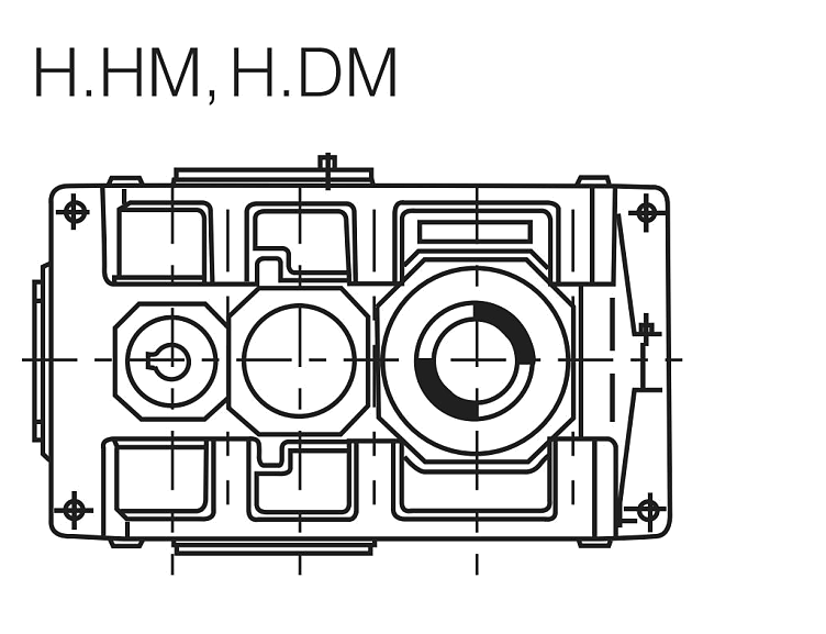
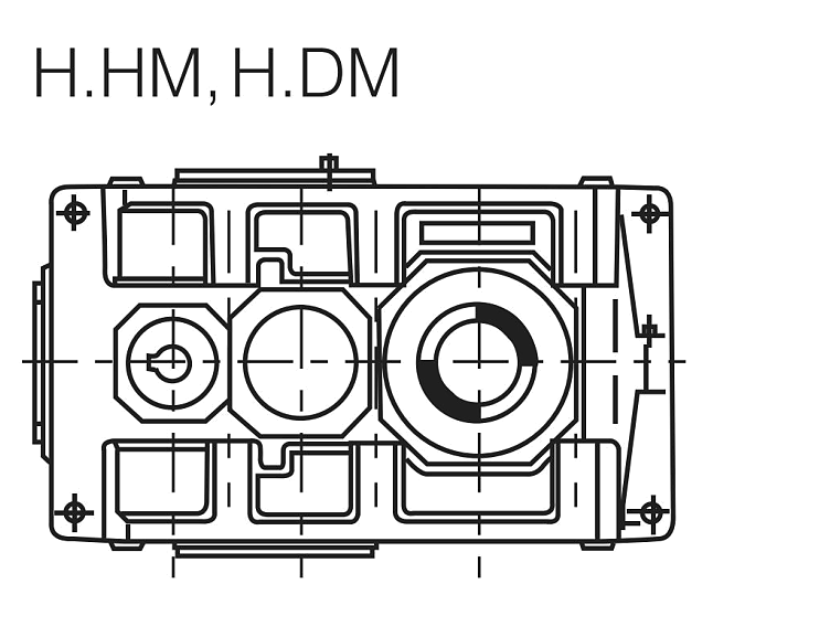
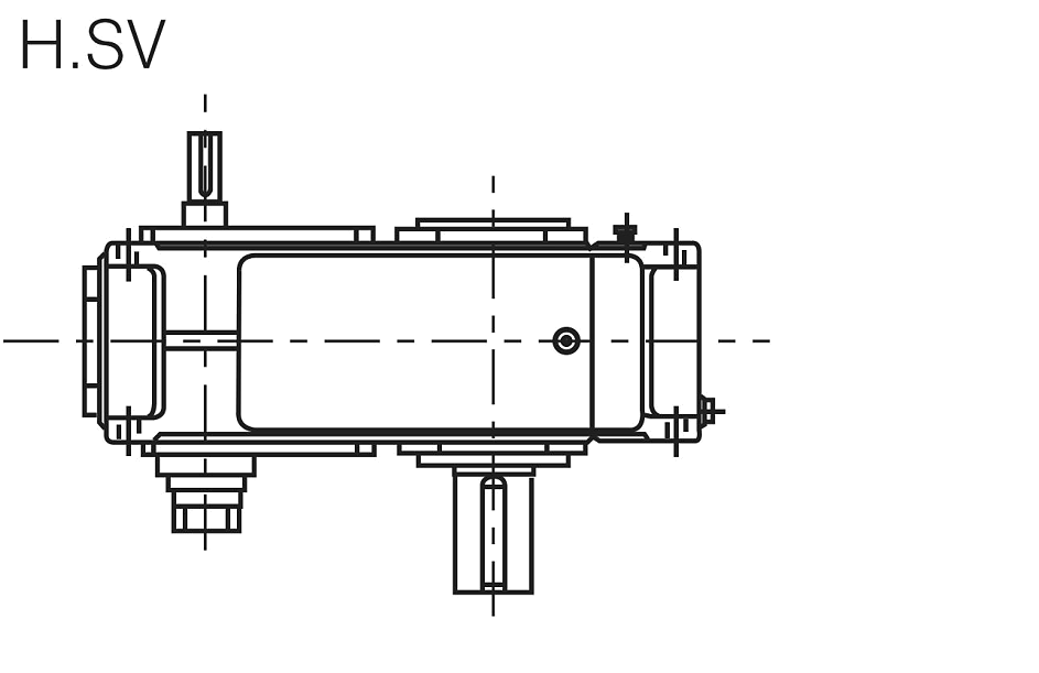
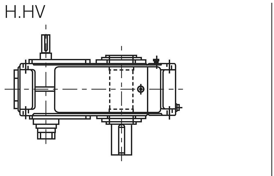
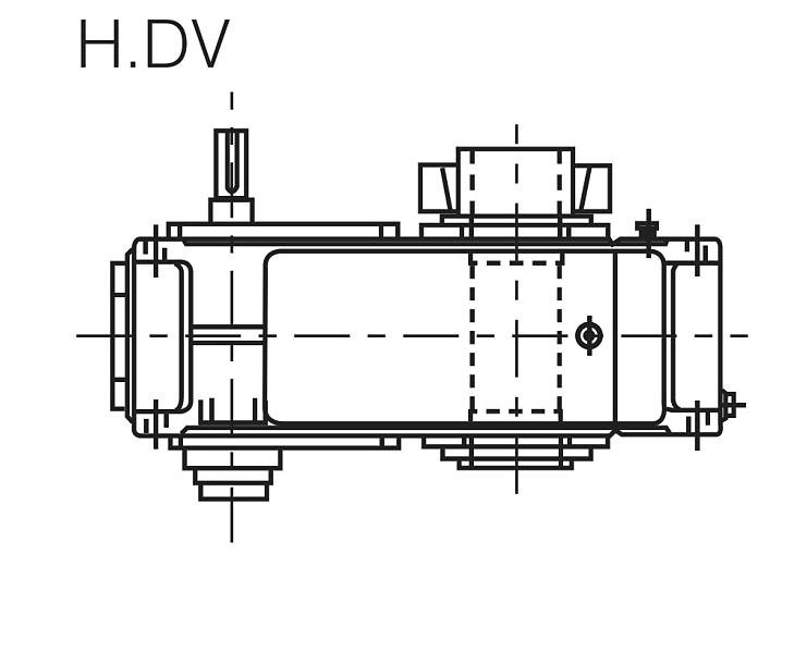
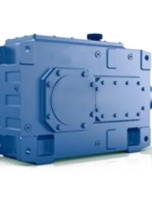
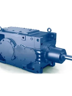
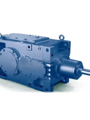
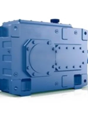
EP-H1 is a single-stage helical parallel-shaft gearbox delivering up to 3.6 kNm in sizes 3–19. Compact, efficient, and available in eight shaft configurations — the ideal solution for conveyors, fans, agitators, and general industrial drives where in-line geometry and high efficiency matter most.
MOQ: Flexible. Minimum order value USD 1,500; mixed orders and trial quantities welcome.
Compact, high-efficiency single-stage speed reduction — the foundation of the HB helical gearbox family. Up to 3.6 kNm, sizes 3–19, eight shaft configurations.
The EP-H1 is a single-stage parallel-shaft helical gear unit — the most direct-action member of the Ever Power HB industrial gearbox series. Where multi-stage units add ratio depth, the H1 optimises for three qualities that matter in space-limited or energy-sensitive installations: maximum efficiency per stage, minimum axial length, and the fewest components between motor and driven machine.
Single-stage does not mean light-duty. Built to the same manufacturing standards as every HB series unit — carburised and ground helical gears, heavy anti-friction bearings, sealed and ribbed cast iron housings — the EP-H1 delivers decades of reliable service in conveyors, agitators, fans, process pumps, and auxiliary drives across the chemical, food, packaging, and material-handling sectors.
Available across sizes 3 through 19 with a maximum output torque of 3.6 kNm at the largest frame, the EP-H1 covers a meaningful band of industrial drive requirements with a compact footprint and an efficiency rating exceeding 98% per stage.
A single helical mesh achieves efficiency values of 98–99% per pass — the best of any geared reduction type. Compared with two-stage units running the same reduction across two meshes, the H1 eliminates the intermediate shaft, its bearings, and the second gear pair. This reduces parasitic losses, lowers the operating temperature, and extends lubricant life.
The compact axial length matters for machine designers. Single-stage parallel-shaft geometry is the shortest in-line speed reducer achievable for a given torque class. Where a multi-stage unit would force a conveyor frame extension or a structural redesign, the H1 fits in the original space allocation.
Part-count reduction also shows up in maintenance economics. Fewer gears and fewer bearings mean fewer inspection points, simpler overhauls, and lower spare-parts inventory. For OEMs with large installed fleets, this translates into a lower total cost of ownership over the equipment lifetime.
EP-H1 covers a continuous size range from 3 to 19. Each size step increases centre distance and gear width, raising the nominal torque capacity in defined increments.
| Size | Nom. Output Torque (kNm) | Max Input Speed (rpm) | Representative Applications |
|---|---|---|---|
| 3 | 0.09 | ≤1500 | Small conveyors, dosing drives |
| 5 | 0.22 | ≤1500 | Packaging feeders |
| 7 | 0.50 | ≤1500 | Roller conveyors, fans |
| 10 | 1.10 | ≤1500 | Agitators, screw conveyors |
| 13 | 1.80 | ≤1500 | Heavy conveyors, mixers |
| 16 | 2.70 | ≤1500 | Industrial fans |
| 19 | 3.60 | ≤1500 | Process fans, centrifuges |
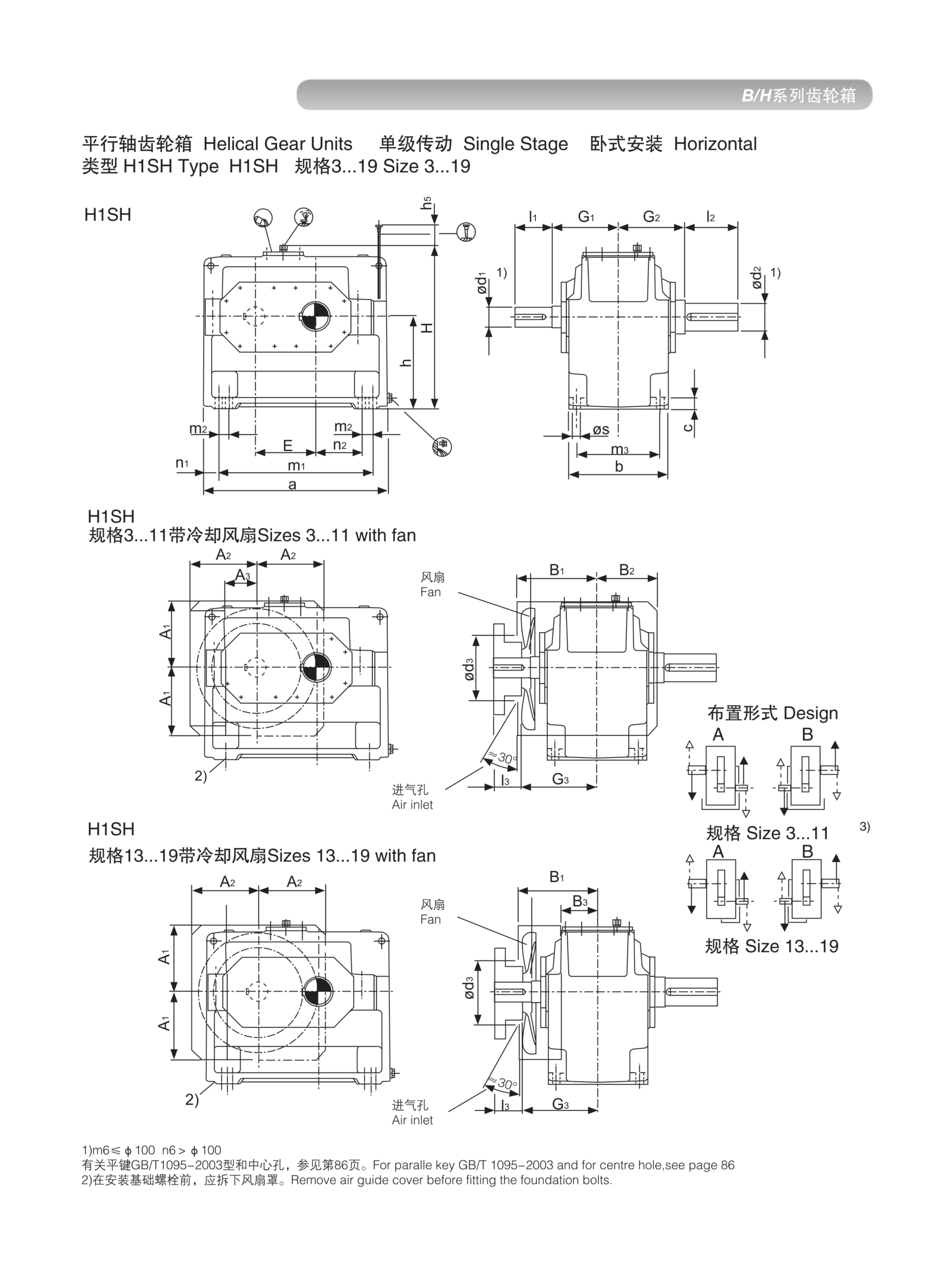
EP-H1 Horizontal Dimension Drawing — Sizes 3–19
Values are nominal continuous-duty torques. Apply service factor for shock, start-stop, or reversing loads before frame selection.
Eight standard configurations ensure the EP-H1 integrates into virtually any machine layout without custom shaft work:
| Code | Description | Typical Use |
|---|---|---|
| HSH | Solid shaft, horizontal | Coupling-connected drives |
| HHH | Hollow bore, horizontal | Shaft-mounted conveyor drives |
| HDH | Shrink-disc hollow, horizontal | High-torque shaft mounting |
| HHM | Hollow bore + motor flange, horizontal | Direct motor-mounted units |
| HDM | Shrink-disc + motor flange, horizontal | High-torque motor mount |
| HSV | Solid shaft, vertical | Vertical agitators, hoists |
| HHV | Hollow bore, vertical | Vertical shaft-mounted drives |
| HDV | Shrink-disc hollow, vertical | High-torque vertical applications |
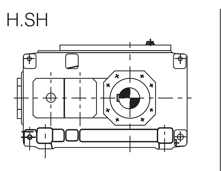
HSH: Solid Shaft Horizontal
HSV: Solid Shaft Vertical
Case depth of 0.8–1.5 mm at 58–62 HRC surface hardness, precision-ground to DIN 5 quality. Smooth tooth engagement, low noise, extended fatigue life under reversed bending loads.
Output shaft bearings sized for L10h ≥ 20,000 hours at rated load and speed. Preloaded to eliminate axial play and maintain gear alignment under thermal cycling.
GG25 or GGG40 housing combines structural stiffness with passive heat rejection. Ribbed exterior dissipates internal heat to the surrounding air without forced cooling under standard ambient conditions.
Standard on all shaft penetrations. Optional V-ring or labyrinth seal upgrades for wash-down environments, food-grade applications, or high-dust atmospheres.
ISO VG 220 PAO synthetic oil enables 20,000-hour change intervals in clean, moderate-temperature installations. Mineral oil supported for cost-sensitive applications.
Standard solid input shaft accepts belt-pulley, sprocket, or coupling connections. Motor-flange versions (HHM/HDM) mount IEC B5/B14 motors directly, eliminating bell-housing components.
The EP-H1's compact geometry and high efficiency make it the preferred choice wherever motor-to-machine torque matching requires a single reduction step:
| Industry | Application | Primary Requirement Met |
|---|---|---|
| Food & Beverage | Mixing agitators, belt conveyors | Low noise, NSF-H1 lubricant option |
| Packaging | Form-fill-seal, labellers, wrapping | Compact envelope, precise ratio |
| Chemical Process | Pump drives, agitators, reactors | Continuous duty, sealed housing |
| HVAC | Fan and blower drives | High efficiency, low heat output |
| Water Treatment | Aerators, slow mixers | Vertical mount, corrosion-resistant seals |
| Material Handling | Roller conveyors, transfer tables | HHH hollow bore for direct shaft mount |
Step 1 — Required Output Torque. Determine the continuous running torque at the output shaft and multiply by the applicable service factor (SF 1.0 for uniform loads; up to SF 2.5 for heavy shock or frequent reversals). The selected size's nominal torque must exceed this factored value.
Step 2 — Speed Ratio. Divide motor speed by required output speed. H1 single-stage ratios typically range from 1.25:1 to 6.3:1 depending on the size selected. For higher ratios, step up to EP-H2, EP-H3, or EP-H4.
Step 3 — Thermal Check. In high-ambient environments or enclosed installations, verify that the unit's thermal power rating — the maximum continuous power the housing can reject to the ambient air — is not exceeded. If it is, specify a cooling fan or choose a larger frame.
Step 4 — Overhung Shaft Loads. If a sprocket, pulley, or pinion is mounted on the output shaft, calculate the resulting radial overhung load and compare it against the bearing load table for that size. Excessive overhung loads reduce bearing life; use the closest practical connection point to the housing face or add outboard support bearings.
Our technical team is available for application-specific review. Send us your drive data and we will confirm the correct size, ratio, and mounting configuration within one business day.
Oil Fill Level. Fill to the level indicator with the unit in its installed orientation. Horizontal and vertical installations have different internal oil paths — never fill a vertically-installed H1 to the horizontal mark or the upper bearings will run dry.
First Service. Replace lubricant after the initial 300–500 operating hours to flush metallic run-in particles before they recirculate through the gear mesh. This single action significantly extends gear and bearing life.
Alignment. For solid-shaft (HSH) versions, align motor and gearbox to within the coupling's rated misalignment tolerance — typically <0.1 mm parallel and <0.1° angular. For hollow-bore (HHH/HDH) versions, the driven shaft surface should be ground to Ra ≤ 0.8 μm to ensure full shrink-fit contact area.
Periodic Inspection. At each maintenance shutdown, inspect shaft seals for weeping, check fastener torques on mounting feet and motor flanges, and verify oil level and condition (colour and viscosity). Oil analysis every 5,000 hours in demanding environments enables condition-based oil changes.
Send us your application torque, speed ratio, and mounting constraints. Our engineers will confirm the correct frame size and provide a quotation within one business day.
Audible noise is evidence to investigate, but fault location depends on whether the sound tracks speed, torque or the machine structure.
Flexible couplings accommodate limited relative movement, but poor shaft alignment still affects bearings and seals.
Oil observed on a housing may have traveled from a vent, joint or shaft seal; finding the first wet point is essential.