Audible noise is evidence to investigate, but fault location depends on whether the sound tracks speed, torque or the machine structure.
Helical Gearbox Noise Diagnosis by Speed and Load
read more

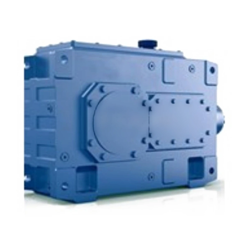
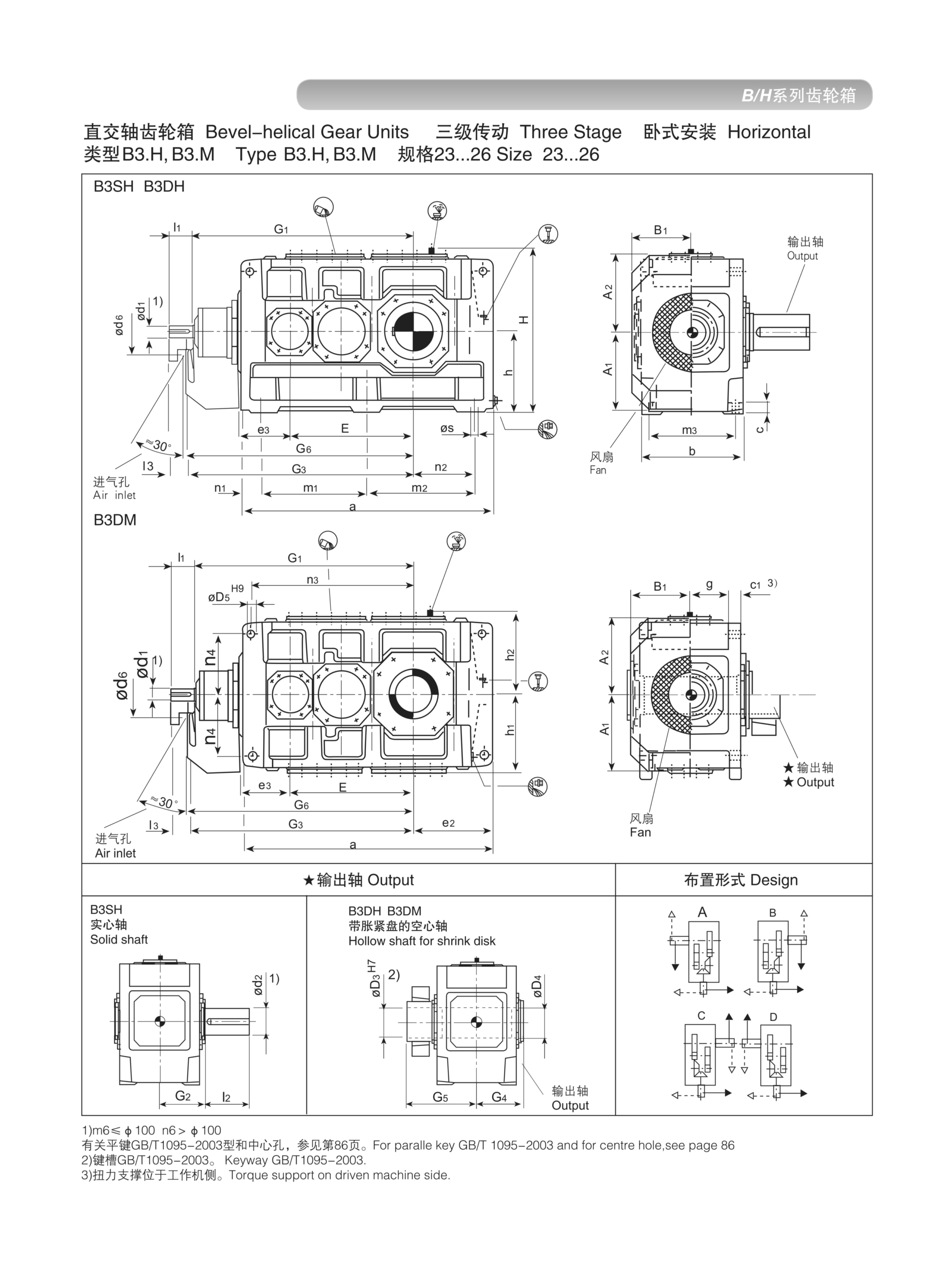
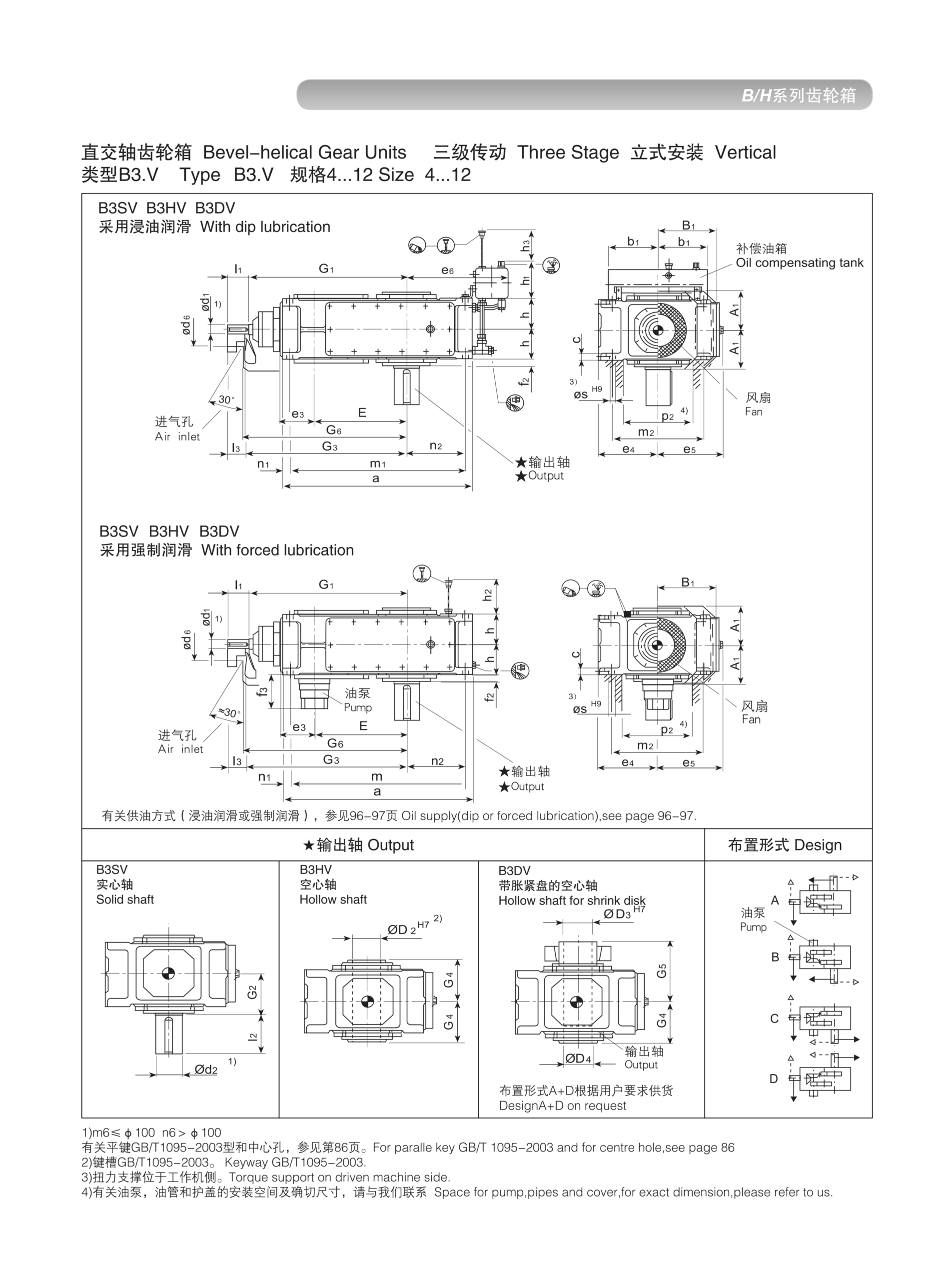
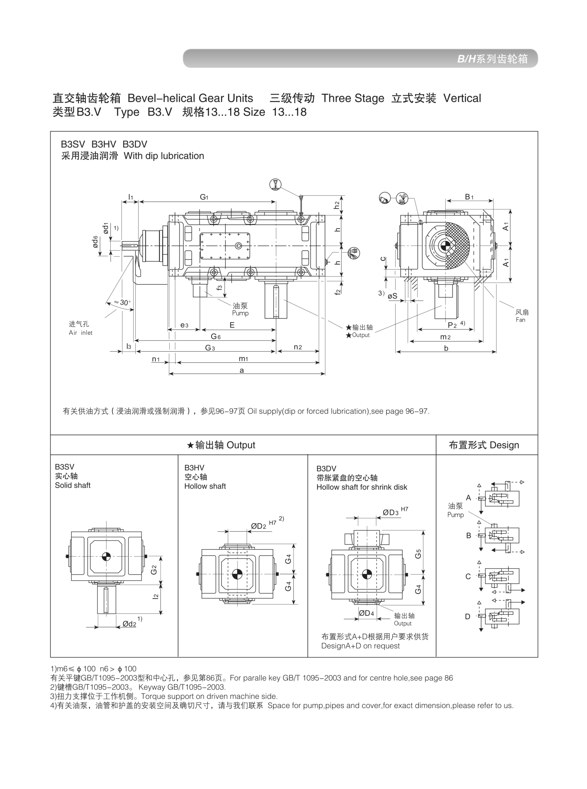
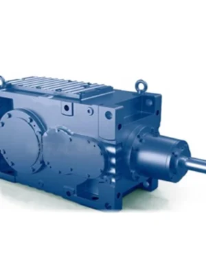
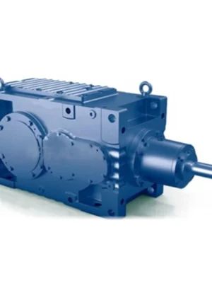
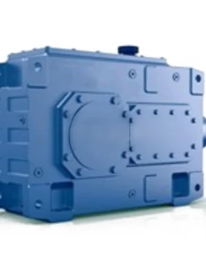
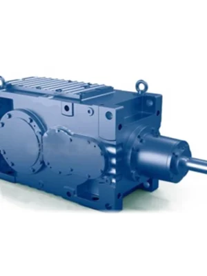
EP-B3 is a three-stage bevel-helical right-angle gearbox with ratios from 25:1 to 280:1 and nominal output torques to 200 kNm in sizes 4–26. Specified for heavy right-angle drives — cooling towers, conveyor corners, ship machinery — where high reduction and right-angle geometry must coexist.
MOQ: Flexible. Minimum order value USD 1,500; mixed orders and trial quantities welcome.
Three-stage right-angle power transmission — bevel input stage plus two helical stages deliver 25:1 to 280:1 ratios and up to 200 kNm in a single compact housing. Sizes 4–26.
The EP-B3 extends the bevel-helical right-angle gearbox concept to three stages — one spiral bevel stage for the 90-degree direction change, followed by two carburised and ground helical stages for deep torque multiplication. The result is a right-angle gearbox capable of overall ratios from 25:1 to 280:1 and a maximum nominal output torque of 200 kNm at the largest frame (Size 26).
The EP-B3 is specified when the application requires both a right-angle shaft layout and a high reduction ratio — a combination that previously required either a custom gearbox, a tandem unit arrangement, or an inefficient worm/worm multi-stage solution. The B3 delivers this combination in a single, factory-assembled, efficiency-optimised unit.
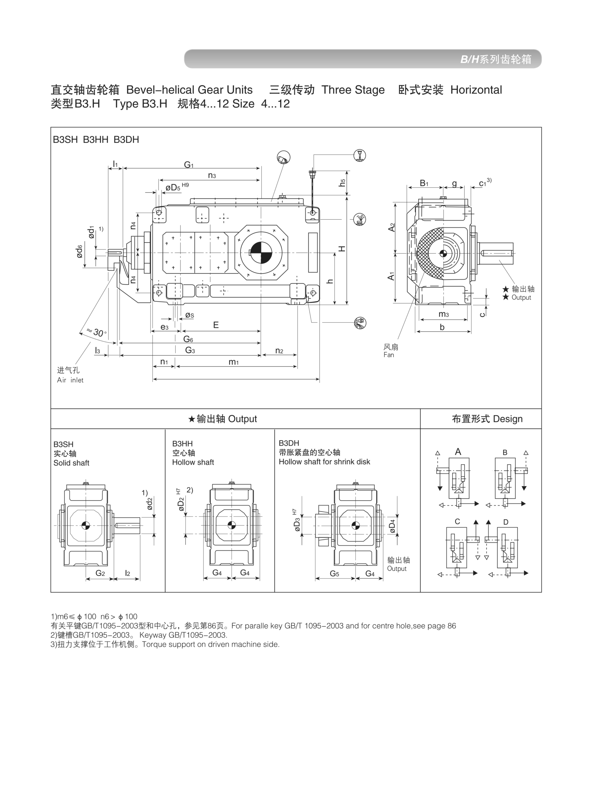
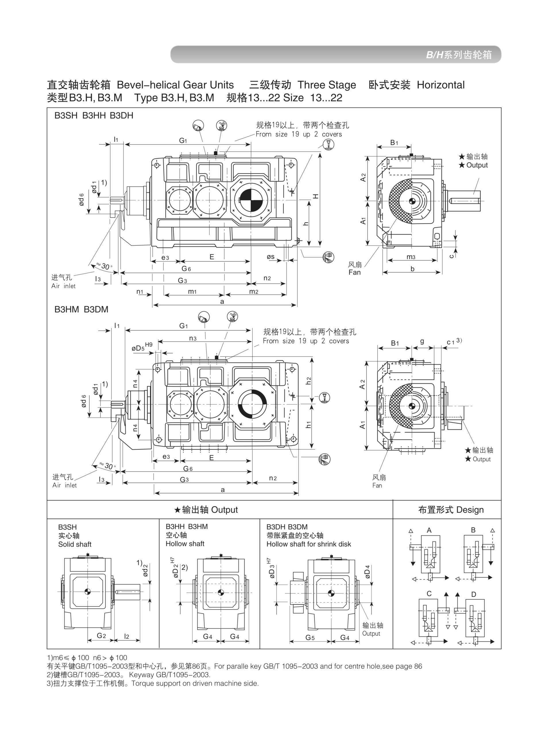
Three dimensional groups (sizes 4–12, 13–22, and 23–26) provide engineering drawing coverage for the full size range, with separate horizontal and vertical drawing sets in each group. Available in nine standard shaft/mounting configurations matching the B-series nomenclature (BSH through BDV).
Adding a third stage to the B2's two-stage layout achieves two specific outcomes that define the B3's engineering value:
First — ratio extension. The B2's two stages reach approximately 45:1. Adding a third helical stage multiplies this by a further 4–6:1, reaching up to 280:1 in a single housing. This covers a class of right-angle drives — slow-turning conveyor corners, ship machinery, large process agitators — where 45:1 is simply not sufficient.
Second — torque capacity increase. Three stages allow the torque to be built up gradually, with each stage operating at a load level below its single-stage optimum. This improves heat distribution, reduces peak tooth contact stresses, and enables a larger output torque (200 kNm) from a housing that would otherwise need to be significantly enlarged to handle the same torque in two stages.
The three-stage B3 maintains the efficiency advantage of the bevel-helical design over worm alternatives. At 95–96% overall efficiency (three stages at approximately 97–99% each), the B3 delivers far more of the motor's input power to the driven machine than any multi-stage worm unit at equivalent ratios.
EP-B3 spans sizes 4 through 26, covering light to very heavy right-angle industrial drives:
| Size | Nom. Output Torque (kNm) | Max Input Speed (rpm) | Ratio Range (i) | Typical Applications |
|---|---|---|---|---|
| 4 | 0.50 | ≤1500 | 25–200 | Small right-angle slow drives |
| 6 | 1.10 | ≤1500 | 25–200 | Packaging, cross conveyors |
| 8 | 2.50 | ≤1500 | 25–250 | Process agitators right-angle |
| 10 | 5.50 | ≤1500 | 25–250 | Heavy cross-conveyors |
| 13 | 14.0 | ≤1000 | 25–250 | Large mixers, ship deck |
| 16 | 35.0 | ≤750 | 25–280 | Heavy right-angle drives |
| 19 | 80.0 | ≤600 | 25–280 | Cooling towers, heavy conveyor corners |
| 22 | 120. | ≤500 | 25–280 | Large process drives |
| 26 | 200. | ≤400 | 25–280 | Heavy mining and cement right-angle |
EP-B3 Horizontal Dimension Drawing — Sizes 4–12
EP-B3 Horizontal Dimension Drawing — Sizes 13–22
EP-B3 Vertical Dimension Drawing — Sizes 4–12
Precision spiral bevel gears redirect the power axis 90 degrees with 98–99% stage efficiency. The bevel gear pair is hardened, finish-ground, and lapped for minimal noise and backlash, setting a high-quality baseline for the downstream helical stages.
Back-to-back carburised and ground helical stages provide the primary ratio multiplication after the bevel direction change. Each helical stage is independently designed to the appropriate tooth load and pitch line velocity for its position in the gear train.
Size groups 4–12, 13–22, 23–26 each have optimised housing proportions. Large-frame units do not merely scale up a small-frame design — each group uses separately calculated gear centre distances and bearing arrangements for optimal strength-to-weight.
The B3 covers the widest size range in the bevel-helical family — from compact 0.5 kNm light-duty right-angle drives up to 200 kNm heavy industrial units. This allows engineers to work within a single product family for an entire machine range.
Typical 95–96% at rated load across the three stages. At high ratios (200:1+) where multi-stage worm efficiency would drop below 50%, the B3's efficiency advantage translates to a 40–50% reduction in motor power draw for the same output shaft power.
BSH, BHH, BDH, BHM, BDM (horizontal) and BSV, BHV, BDV (vertical). The right-angle input/output relationship is maintained in all configurations, with the output shaft direction determined by the mounting configuration selected.
EP-B3 is specified wherever the right-angle layout of B2 is needed but the required ratio or torque exceeds B2's two-stage capability:
| Industry | Application | Primary Requirement |
|---|---|---|
| Conveyor Systems | 90° corner drives, transfer units | Right-angle, high ratio, shock |
| Cooling Towers | Fan drives, counterflow fans | Right-angle, continuous duty |
| Ship & Port Machinery | Deck winches, slew drives | High torque, compact footprint |
| Cement | Right-angle bucket elevator drives | Heavy shock, 24/7 duty |
| Chemical Process | Large agitators, right-angle reactor drives | Slow speed, high torque, sealed |
| Agricultural Processing | Grain elevators, mixer drives | Right-angle, intermittent peaks |
| Model | Stage Architecture | Ratio Range | Max Torque | Best Fit |
|---|---|---|---|---|
| EP-B2 | 1 bevel + 1 helical | 5–45:1 | 90 kNm | Compact, moderate ratio right-angle drives |
| EP-B3 | 1 bevel + 2 helical | 25–280:1 | 200 kNm | High ratio right-angle heavy process |
| EP-B4 | 1 bevel + 3 helical | 50–500:1 | 500 kNm | Ultra-high ratio right-angle heavy industry |
If your ratio falls between 25:1 and 280:1 with torque up to 200 kNm in a right-angle layout, the EP-B3 is the correct unit. For ratios above 280:1, proceed to EP-B4.
Provide required ratio, output torque, mounting orientation, and ambient conditions. Our engineering team will specify the correct B3 size and confirm lead time within one business day.
Audible noise is evidence to investigate, but fault location depends on whether the sound tracks speed, torque or the machine structure.
Flexible couplings accommodate limited relative movement, but poor shaft alignment still affects bearings and seals.
Oil observed on a housing may have traveled from a vent, joint or shaft seal; finding the first wet point is essential.