CL Type Gear Coupling — Crowned Tooth, General Purpose, 16 Sizes
The standard crowned-tooth gear coupling per GB/T5843 for general industrial drives worldwide. Compact, reliable, and economical — available in CL (standard) and CLZ (extended sleeve) configurations. Factory direct from stock or to custom bore specification.
Torque Range
40 – 40,000 N·m
Product Overview
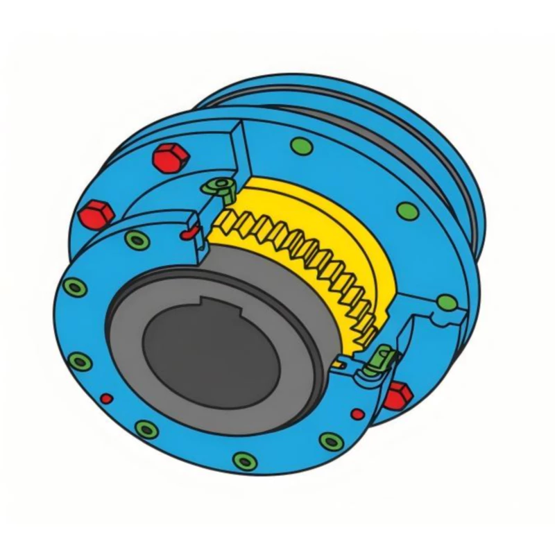
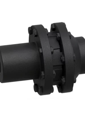
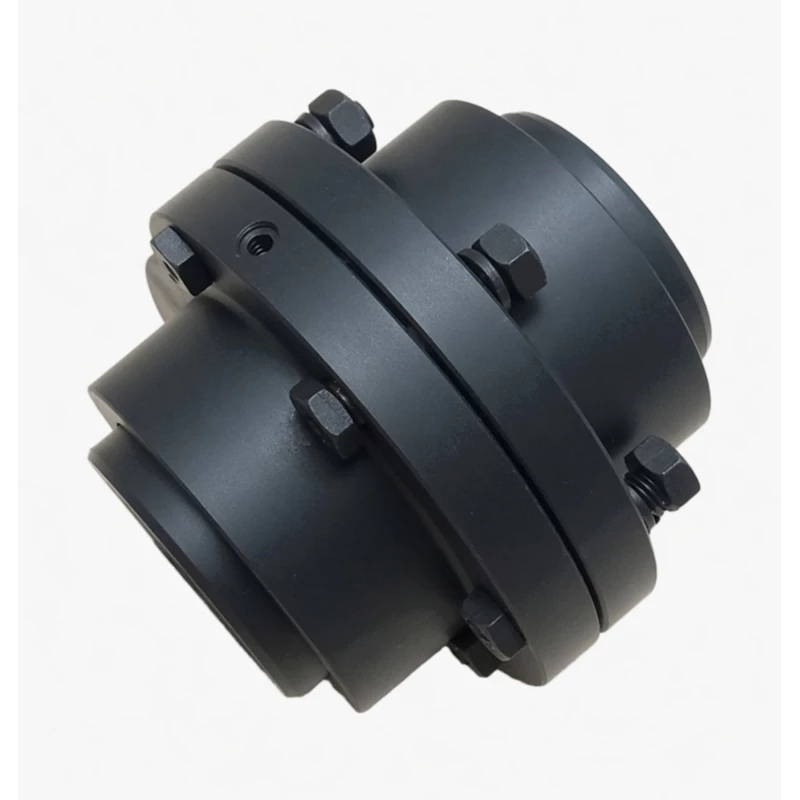
The CL type gear coupling is a crowned tooth (drum shape) flexible coupling per GB/T5843, designed for general industrial shaft-to-shaft connections across a full range of applications. It is the most widely used gear coupling standard in Chinese industry.
The CL coupling consists of two inner hubs — each with external crowned gear teeth — and a single outer sleeve with internal straight teeth connecting both hubs. The crowned tooth mesh transmits torque while simultaneously accommodating angular, radial, and axial shaft misalignment, protecting motor and gearbox bearings from misalignment-induced loading. Two variants are available: CL (compact standard configuration) and CLZ (with extended outer sleeve for wider shaft gaps), both using the same inner hub geometry and bore specifications.
Technical Definition and Working Principle
What Makes the CL a Crowned Tooth Coupling — Not a Straight Tooth Coupling
The key distinction between a CL type crowned tooth gear coupling and a conventional straight tooth gear coupling lies in the geometry of the external teeth on the inner hubs. In a straight tooth gear coupling, tooth flanks are machined flat and parallel to the shaft axis — producing a line contact spanning the full tooth face width. In the CL's crowned tooth design, the tooth profile is barrel-shaped — thickest at its mid-point and tapering toward both ends. This geometry produces a Hertzian contact ellipse near the tooth centre rather than a line contact across the full face.
The practical consequence of this difference is significant: a straight tooth coupling generates contact stress that rises steeply at the tooth edges whenever angular misalignment is present — even small misalignments of 0.1 to 0.2 degrees concentrate the full tooth load at one edge, quickly exceeding the tooth surface fatigue limit. The CL's crowned tooth maintains its contact ellipse near the tooth centre even at angular misalignment of up to 1.5 degrees, distributing load uniformly regardless of shaft angle — eliminating edge loading entirely.
The Three Misalignment Modes and How the CL Handles Each
The CL coupling accommodates three types of shaft misalignment simultaneously, each through a different mechanism in the crowned tooth mesh.
- Angular misalignment — The crowned tooth profile allows the inner hub to tilt relative to the outer sleeve's internal gear ring without generating edge stress. The self-centring nature of the crowned contact keeps the tooth engagement near centre regardless of tilt angle up to the rated maximum of 1.5 degrees per mesh (approximately 1 degree recommended for continuous service).
- Radial (parallel) misalignment — Parallel offset between the two shaft axes causes each coupling half to tilt slightly in the outer sleeve, absorbing the offset as angular displacement at each tooth mesh. The CL coupling accommodates radial offset up to approximately 0.3–0.5 mm for smaller sizes, increasing proportionally with size.
- Axial displacement — Thermal growth of shafts during operation, and installation clearances, are absorbed by the axial sliding of the inner hub teeth within the outer sleeve. The CL accommodates plus or minus 2 to 4 mm of axial displacement without generating thrust forces at the shaft bearings, protecting motor and gearbox bearings from axial loading that causes premature race failure.
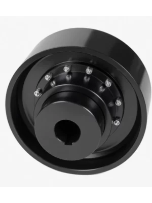
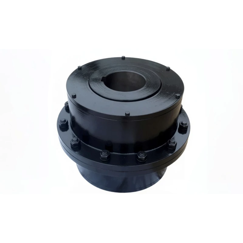
CL Architecture — Inner Hubs, Outer Sleeve, and Lubrication
Each CL coupling consists of two identical inner hubs (mounting on their respective shafts via parallel keyway bore or taper bore) and a single outer sleeve. The sleeve has internal straight teeth machined on its bore at both ends, each meshing with one inner hub's external crowned teeth to form the two-mesh torque transmission path. A lubrication fill port at the mid-span of the outer sleeve provides access for grease injection. The sleeve is retained on the hubs by the tooth mesh engagement and a seal arrangement at each end.
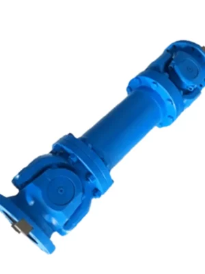
The CLZ variant uses an extended outer sleeve — longer overall length with the same internal gear tooth geometry at each end — providing a wider shaft gap capability from the same inner hub components. This is equivalent in function to a spacer coupling, allowing the CL hub geometry to be used wherever a longer shaft span is required without changing the inner hub design.
CL vs Other Coupling Types — Performance Comparison
| Feature |
CL Type (this product) |
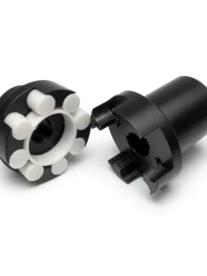
Jaw Coupling |
Disc Coupling |
Straight Tooth Gear Coupling |
| Misalignment Tolerance |
High — crowned tooth, up to 1.5 deg |
Moderate (elastomer deflects) |
Low — disc pack torsionally stiff |
Low — edge loading above 0.1 deg |
| Shock Load Tolerance |
Excellent — no elastomer to shear |
Good (elastomer absorbs, then fails) |
Poor — disc pack fatigues rapidly |
Poor — edge overload at each shock |
| Torque-to-Size Ratio |
High — compact gear mesh |
Moderate |
Moderate–High |
High (but shorter service life) |
| Maintenance |
Periodic re-lubrication |
Elastomer replacement 1–3 years |
Low maintenance (no lube needed) |
Periodic re-lube; shorter intervals |
| Torque Range |
40 – 40,000 N·m (CL1–CL16) |
Up to ~3000 N·m typically |
Wide range |
Wide but shorter service life |
CL vs CLZ — Which Variant to Choose
Both CL and CLZ use identical inner hubs for the same size number, share the same torque rating, bore range, and speed limit, and are assembled using the same installation procedure. The only structural difference is the outer sleeve length.
| Factor |
CL — Standard Compact |
CLZ — Extended Sleeve |
| Outer Sleeve Length |
Standard B dimension per GB/T5843 |
Extended B dimension — longer overall assembly |
| Shaft Gap Capability |
Standard — motor to machine close-coupled |
Wider — spans larger shaft-end gaps |
| Torque Rating |
Same as CLZ (same size number) |
Same as CL (same size number) |
| Bore Range |
Same as CLZ |
Same as CL |
| Speed Rating |
Same as CLZ |
Same as CL — verify critical speed for long sleeves |
| Weight |
Lighter — shorter sleeve |
Heavier — extended sleeve adds mass |
| Axle Withdrawal |
No — shaft must move axially to remove coupling |
Limited — longer sleeve allows some access clearance |
| Price |
Lower — less sleeve material |
Slightly higher — additional sleeve length |
| Choose When... |
Standard close-coupled drive; no shaft gap constraint; minimum weight and cost |
Wider shaft separation; structural clearance between motor and machine; limited axle access requirement |
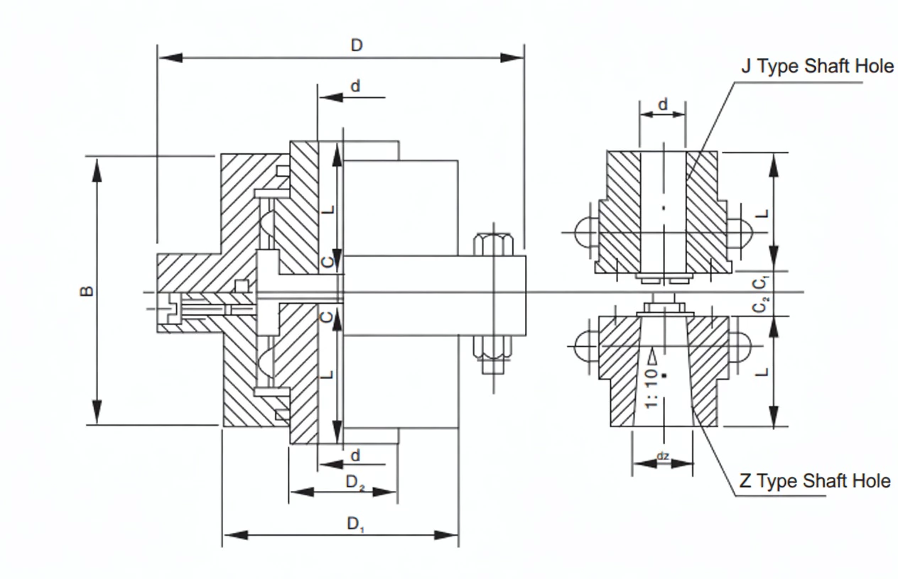
Specifications & Size Matrix — CL1 to CL16
All specifications per GB/T5843. Bore diameter range (d min to d max) for Y type cylindrical bores. Maximum bore diameter for Z taper bores is the same as Y type maximum. J1 type bores are available where L engagement length is greater than Y type at the same bore diameter.
CL1 – CL16 Main Specifications
| Size |
Nominal Torque
Tn (N·m) |
Max Speed
(rpm) |
Bore Range
d (mm) |
Y bore length
L range (mm) |
Outer Dia
D (mm) |
CL Length
B (mm) |
CLZ Length
B1 (mm) |
Angular
Tolerance |
CL Weight
(kg approx) |
| CL1 |
40 |
4750 |
10–16 |
25–32 |
80 |
60 |
90 |
1.5 deg |
1.2 |
| CL2 |
63 |
4750 |
10–22 |
25–52 |
100 |
72 |
110 |
1.5 deg |
2 |
| CL3 |
100 |
4000 |
12–28 |
25–60 |
120 |
84 |
125 |
1.5 deg |
3.5 |
| CL4 |
160 |
3150 |
16–35 |
32–82 |
145 |
100 |
148 |
1.5 deg |
5.5 |
| CL5 |
250 |
2800 |
20–45 |
42–112 |
175 |
120 |
175 |
1.5 deg |
9 |
| CL6 |
400 |
2500 |
25–55 |
52–142 |
210 |
140 |
205 |
1.5 deg |
16 |
| CL7 |
630 |
2240 |
32–65 |
60–172 |
250 |
165 |
240 |
1.5 deg |
26 |
| CL8 |
1000 |
2000 |
40–80 |
84–212 |
295 |
190 |
280 |
1.5 deg |
42 |
| CL9 |
1600 |
1800 |
50–95 |
107–252 |
350 |
225 |
330 |
1.5 deg |
65 |
| CL10 |
2500 |
1600 |
60–110 |
107–302 |
415 |
265 |
390 |
1.5 deg |
105 |
| CL11 |
4000 |
1400 |
75–130 |
132–352 |
485 |
310 |
455 |
1.5 deg |
165 |
| CL12 |
6300 |
1250 |
90–160 |
172–410 |
570 |
365 |
535 |
1.5 deg |
260 |
| CL13 |
10000 |
1120 |
110–200 |
212–470 |
670 |
430 |
630 |
1.5 deg |
415 |
| CL14 |
16000 |
1000 |
130–240 |
252–550 |
790 |
500 |
735 |
1.5 deg |
650 |
| CL15 |
25000 |
900 |
160–280 |
302–650 |
930 |
585 |
860 |
1.5 deg |
1030 |
| CL16 |
40000 |
800 |
190–320 |
352–750 |
1090 |
680 |
1000 |
1.5 deg |
1600 |
Note: Weight values are approximate, based on maximum bore Y type. Bore ranges shown are for Y type; J1 type bores use the same bore diameter range with increased engagement length L. Z taper bores (1:10) are available up to the maximum bore diameter shown. CLZ B1 length values indicate the extended sleeve variant. All torque ratings are nominal (Tn); multiply by 1.25 for peak torque check in the selection calculation.
Custom Bore, Non-Standard Engagement Length, and CL/CLZ Available Together
Any bore diameter within the range for the chosen CL size can be machined to your shaft drawing — including metric IEC motor shaft sizes (14, 19, 24, 28, 38, 42, 48, 55, 60, 65, 75, 80 mm and above). Both CL and CLZ sleeves can be ordered for the same pair of inner hubs, allowing future sleeve exchange if the shaft gap changes. Send your shaft drawing or motor frame size for a confirmed bore specification.
Technical Advantages — Why Crowned Tooth Outperforms Straight Tooth
Longer Service Life Under Shock Loads
Every industrial drive experiences shock loads — conveyor belt starts under load, compressor pressure build-up, mixer blade contact with oversize material, and pump cavitation events all generate torque spikes of 2–4× running torque. The CL's crowned teeth distribute these peaks as Hertzian contact ellipses at the tooth flank centre, with no edge stress concentration.
Reduced Bearing Loads — Protecting Motor and Gearbox Bearings
Lower Maintenance Frequency — Less Downtime Per Year
CL couplings require periodic re-lubrication (every 6–12 months) and periodic tooth wear inspection — but no consumable elastomers, no disc pack replacement, and no wear-induced misalignment. The typical CL coupling replacement interval in a well-lubricated, correctly aligned installation is 5–10 years in standard industrial duty, compared to 1–3 years for jaw couplings and 2–5 years for disc pack couplings in the same duty.
Suitable for High-Speed Applications — Up to 4750 RPM
CL1 through CL4 are rated to 4750 and 3150 RPM respectively — fully compatible with 2-pole IEC motors. For applications above 2500 RPM, the coupling must be balanced to ISO 1940/1 Grade G6.3 or better, and the bore fit should be H7/k6 to ensure concentricity. The CL's metal-only construction means there is no speed-dependent degradation from centrifugal loading on flexible elements, unlike jaw couplings at high speed.
Manufacturing & Quality Assurance
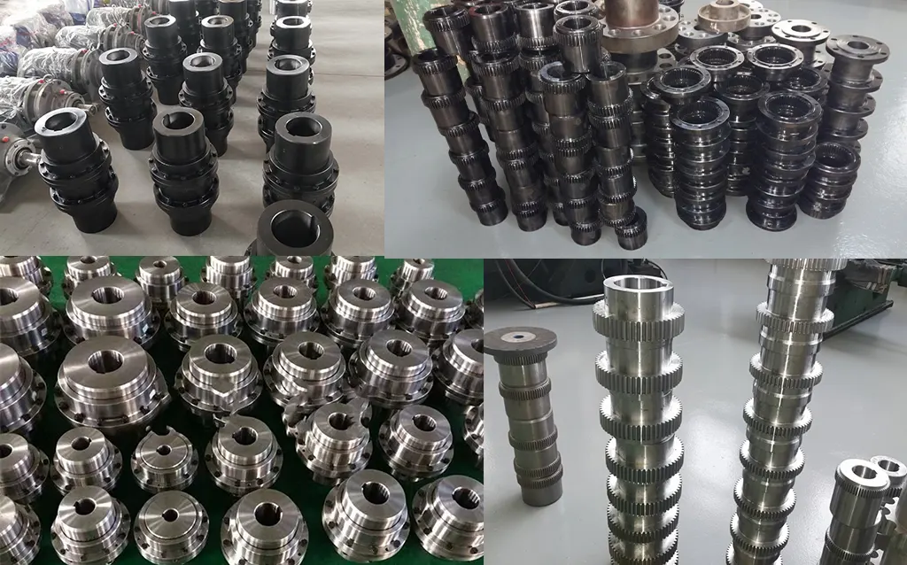
Manufacturing Process
CL inner hubs are manufactured from forged steel blanks — 45# carbon steel for smaller sizes (CL1–CL8) and 42CrMo4 alloy steel for larger sizes (CL9–CL16). The outer sleeves are machined from seamless alloy steel tube or forged rings depending on size. Crowned teeth are CNC hobbed to GB/T10095 Class 8 accuracy. Tooth flanks are either induction hardened (CL1–CL10) or carburised and quench hardened (CL11–CL16) to HRC 50–58 surface hardness with HRC 28–35 core hardness.
All bores are finish-machined after heat treatment to H7 tolerance using CNC boring or grinding. Keyways are broached to JS9 tolerance. Z type taper bores (1:10) are verified with taper plug gauges and blue contact checks for minimum 75% contact before acceptance.
Quality Control Flow
STEP 1
Material Inspection & Chemistry Certification
STEP 2
CNC Hobbing, Bore Machining & Keyway Broaching
STEP 3
Induction Harden or Carburise & Quench
STEP 4
Gear Profile, Bore Tolerance & Hardness Inspection
STEP 5
Mesh Assembly Check, Lubrication Fill & Pack
Certifications
ISO 9001:2015 quality management certification covers the full CL/CLZ manufacturing process. CE marking is applicable to relevant export sizes. Products manufactured per GB/T5843. Every shipment includes material mill certificates with heat traceability, heat treatment records, Rockwell hardness test certificates, and dimensional inspection reports.
Why Source Your CL Couplings from RP?