
A bevel stage redirects rotation, but the housing reaction, shaft support and access must still match the final machine. Direction mistakes can jam a conveyor or reverse a process screw. Refer to the K-series right-angle drives guidance. Compare rotation with the proposed bevel gear train and motor wiring plan. Approve both reducer position and structure rather than only bolt-hole compatibility.
Draw the rotation vectors
Design reaction arms separately
Include motor withdrawal envelope
Draw the rotation vectors
The bevel stage changes shaft axis direction while preserving a defined input-output rotation relationship; a machine may require a particular direction at the work roll when the motor turns clockwise from a stated viewpoint.
Direction mistakes can jam a conveyor or reverse a process screw; annotate motor and output viewing directions with arrows on an assembly drawing.
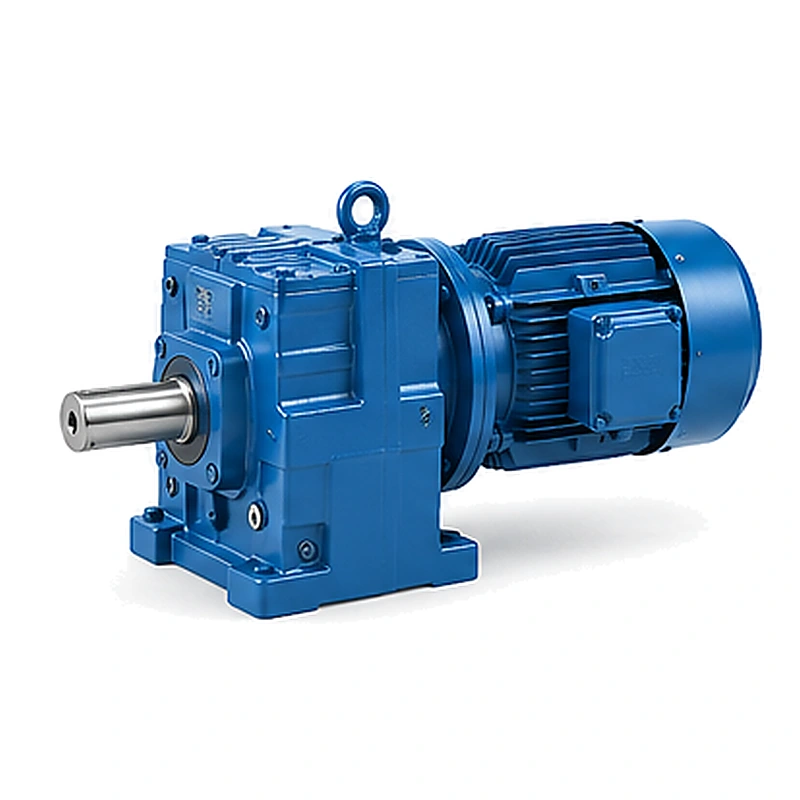
Compare rotation with the proposed bevel gear train and motor wiring plan; commissioning must verify actual driven direction before applying production load; a right-angle diagram alone does not reveal the sign of the output rotation.
Choose footing and flange support
K foot-mounted and KF flange arrangements impose different reaction loads on the machine frame; an elevated flange support may suffer bending that a floor-mounted assembly avoids.
Bolting a heavy reducer to an unreinforced sheet enclosure can distort alignment; identify weight, mounting planes, bolt groups and available machine stiffness.
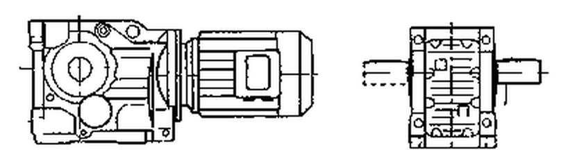
Obtain the gearmotor drawing and allowable mounting arrangement; approve both reducer position and structure rather than only bolt-hole compatibility; the frame can be the weak link even when the gear train is adequately sized.
Evaluate a hollow-output mount
KA and KAF variants transfer torque directly into a driven shaft that needs its own support design; a hollow mounting can eliminate an external coupling but does not automatically support a long machine shaft.
An unsupported output can impose bending loads outside a gearbox rating; measure hollow bore, key or clamping connection, shaft shoulder and load lever arm.
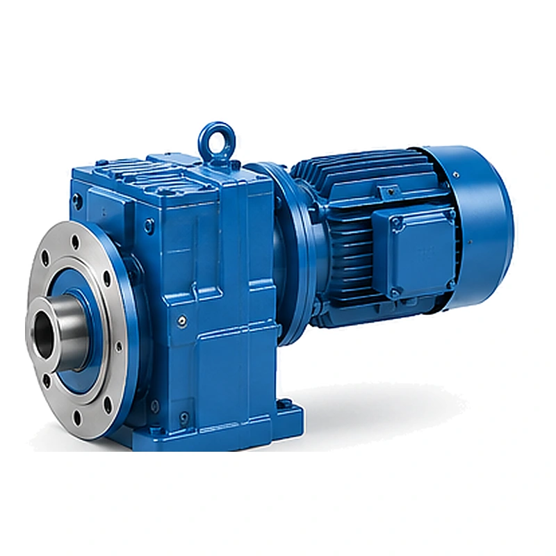
Compare the bearing scheme of machine and reducer with permitted Fr and Fa ratings; accept a connection only with confirmed fit, restraint and external load limits; a clean drawing of a short hollow assembly can hide inadequate bearing support.
Design reaction arms separately
KAT structural arrangements require a controlled resisting moment when shaft-mounted; the arm angle and its joint constraints matter during drive reversals and thermal changes.
A reaction arm installed at the wrong angle can add transverse housing force; specify torque direction, arm length and permissible joint movement.
Record the support bracket and its fastener loading at peak duty; approve an arrangement that carries torque reaction without overconstraining the shaft; a large bolt does not make a poorly directed reaction load disappear.
Account for external axial thrust
Bevel gear trains generate internal thrust while the driven equipment can also impose external thrust; an auger or agitator may push along the output axis in one process direction.
Confusing internal bearing design with free external thrust capacity is hazardous; draw external thrust magnitude, direction and application point at the machine shaft.
Request manufacturer combined Fr and Fa approval for the selected output; the allowed external load must reflect operating speed and bearing-life conditions; a rated output torque figure is not an axial-force rating.
An auger or agitator may push along the output axis in one process direction. Confusing internal bearing design with free external thrust capacity is hazardous. Examine the K-series right-angle drives layout example. Request manufacturer combined Fr and Fa approval for the selected output. The allowed external load must reflect operating speed and bearing-life conditions.
Confirm vertical lubrication paths
Some right-angle gearboxes operate with an upward or downward output orientation; a shaft positioned above the oil level may rely on a specific lubrication feature.
A shipping fill position cannot define the correct in-service oil quantity; record actual input and output shaft attitudes and intended filler location.
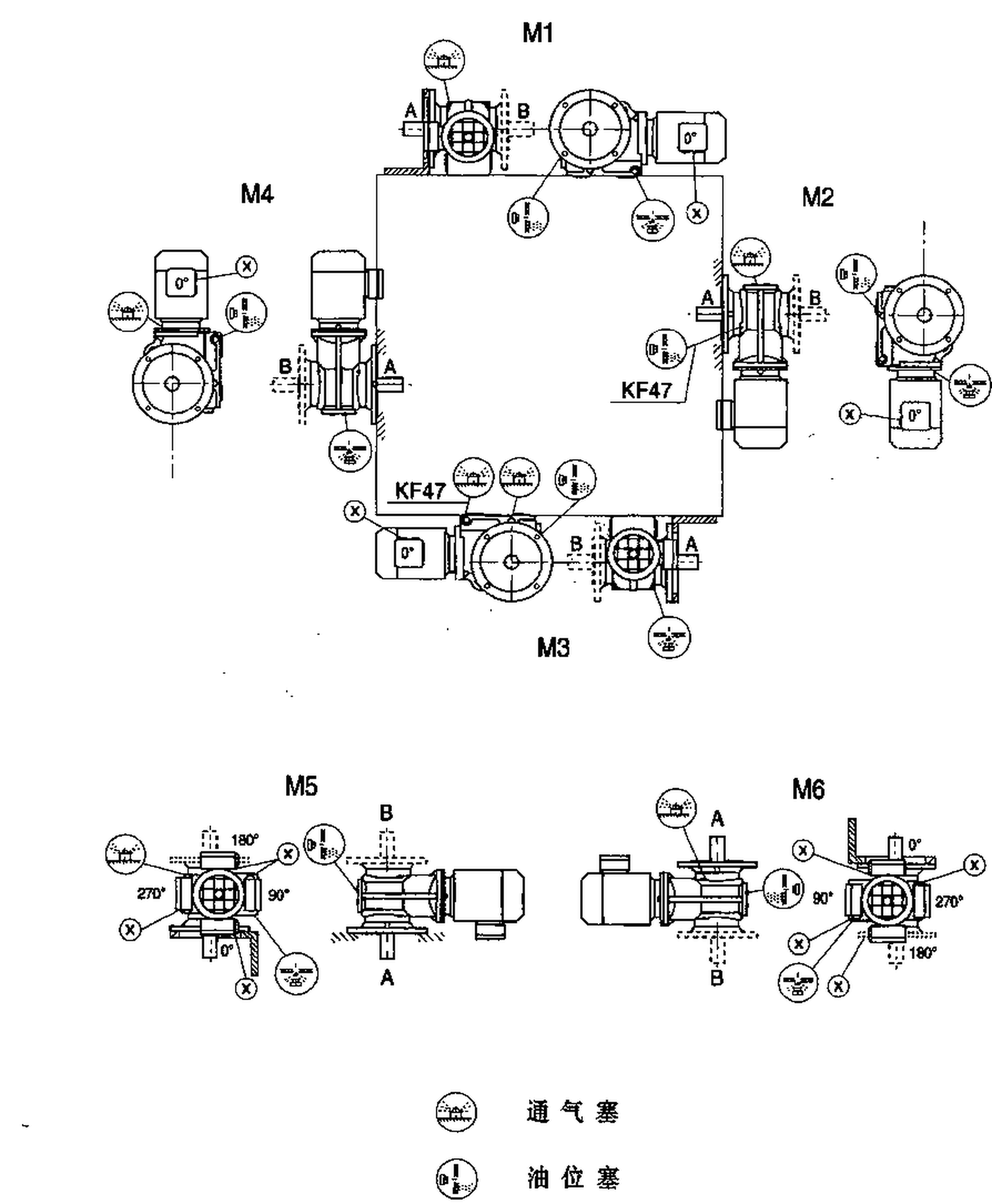
Obtain the mounting code and exact lubricant instructions for that posture; authorize operation only after the supplier confirms bearing oil delivery; missing oil-level verification creates a risk that is invisible at purchase.
Include motor withdrawal envelope
Right-angle drives save length in one direction but occupy width in another; a motor near the wall can make fan, terminal box and brake maintenance difficult.
A three-dimensional clash check limited to installed geometry is insufficient; model the removal path for motor, coupling, brake and oil service parts.
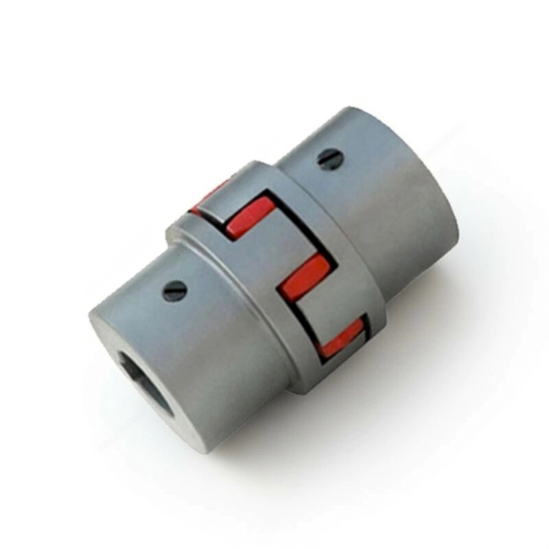
Dimension the nearby guard openings and lifting clearances; check the proposed service route with the maintenance owner; an inaccessible drive may be economical to build but expensive to maintain.
Control procurement configuration
Right-angle variants can differ in flange, bore, motor and restraint details; two offers using the same ratio may refer to quite different physical assemblies.
Without an agreed general arrangement the buyer risks ordering a near-fit; attach duty, rotation, installation drawing and requested accessories to every RFQ.
Require the selected structural suffix and approved dimensional drawing in the offer; acceptance should verify the delivered full unit against the agreed drawing; model-family similarity is not a replacement certificate.
Illustrative engineering scenario: A ninety-degree machine drive where motor and load axes intersect at right angles
Take a hypothetical auger drive installed on a vertical support frame. The motor must remain horizontal, while the auger shaft runs at right angles to it. A K-series helical-bevel arrangement is a plausible geometry to investigate because the bevel stage redirects the axis. On the first sketch, the integrator defines clockwise and counterclockwise from stated viewing directions. This avoids the ambiguity of a drawing that shows arrows without saying which end of the shaft the observer faces. The real output direction must be confirmed against the proposed geartrain and motor wiring before moving material.
The existing auger has its own thrust bearing near the process vessel. That bearing arrangement should be retained or consciously redesigned; gearbox output bearings should not be assumed to take additional process thrust. The engineer supplies the maximum external axial force, output speed and direction of thrust to the gearbox maker, together with the shaft support drawing. If a hollow-shaft K variant is considered, the bore and retention method must be checked as a complete mechanical interface. A foot-mounted layout and a torque-arm arrangement will have different reaction paths and cannot be reduced to one line on a bill of materials.
The site layout has a second constraint: the motor is near a walkway wall, and the planned cover may block fan service and oil draining. Moving the reducer to clear the structural beam could create a new problem with lubricant position. The comparison therefore includes installation orientation, filler and breather locations, access for motor removal, and the location of any guard. A final proposal is not simply a ratio and a power figure; it is a signed arrangement with verified shaft direction, permitted external forces, accepted thermal conditions and practical maintenance clearances.
Five-stage review for a ninety-degree machine drive where motor and load axes intersect at right angles
- Draw the rotation vectorsAnnotate motor and output viewing directions with arrows on an assembly drawing. Commissioning must verify actual driven direction before applying production load.
- Choose footing and flange supportObtain the gearmotor drawing and allowable mounting arrangement. The frame can be the weak link even when the gear train is adequately sized.
- Design reaction arms separatelySpecify torque direction, arm length and permissible joint movement. Approve an arrangement that carries torque reaction without overconstraining the shaft.
- Confirm vertical lubrication pathsObtain the mounting code and exact lubricant instructions for that posture. Missing oil-level verification creates a risk that is invisible at purchase.
- Control procurement configurationAttach duty, rotation, installation drawing and requested accessories to every RFQ. Acceptance should verify the delivered full unit against the agreed drawing.
Engineering comparison matrix: K series helical bevel gearbox layout
| Engineering question | Evidence to collect | Review decision |
|---|---|---|
| Draw the rotation vectors | Compare rotation with the proposed bevel gear train and motor wiring plan. | Commissioning must verify actual driven direction before applying production load. |
| Choose footing and flange support | Obtain the gearmotor drawing and allowable mounting arrangement. | Approve both reducer position and structure rather than only bolt-hole compatibility. |
| Evaluate a hollow-output mount | Compare the bearing scheme of machine and reducer with permitted Fr and Fa ratings. | Accept a connection only with confirmed fit, restraint and external load limits. |
| Design reaction arms separately | Record the support bracket and its fastener loading at peak duty. | Approve an arrangement that carries torque reaction without overconstraining the shaft. |
| Account for external axial thrust | Request manufacturer combined Fr and Fa approval for the selected output. | The allowed external load must reflect operating speed and bearing-life conditions. |
| Confirm vertical lubrication paths | Obtain the mounting code and exact lubricant instructions for that posture. | Authorize operation only after the supplier confirms bearing oil delivery. |
Frequently Asked Questions
How can a right-angle gearbox reverse the driven shaft direction?
Can the K-series output take process thrust from an auger?
Is a KAF hollow flange gearbox the same mechanical fit as a KF unit?
What should be checked when the K gearbox is mounted vertically?
What makes a final review credible for a ninety-degree machine drive where motor and load axes intersect at right angles?
A motor near the wall can make fan, terminal box and brake maintenance difficult. When comparing actual mounting geometry, use the K-series right-angle drives configuration options. Dimension the nearby guard openings and lifting clearances.
Attach duty, rotation, installation drawing and requested accessories to every RFQ. For an engineering quotation that records the open conditions, contact the technical team about K-series right-angle drives. Acceptance should verify the delivered full unit against the agreed drawing.
Engineering sources for K-Series Helical Bevel Gearbox — Planning a Right-Angle Drive
For the k-series helical bevel gearbox: planning a right-angle drive workflow, consult these reference documents alongside the actual model installation manual:
- K-Series Helical Bevel Gearbox: Planning a Right-Angle Drive: SEW-EURODRIVE, Dimension sheet information (analysis).
- K-Series Helical Bevel Gearbox: Planning a Right-Angle Drive: SEW-EURODRIVE, Change of mounting position (interface review).
- K-Series Helical Bevel Gearbox: Planning a Right-Angle Drive: SKF, Bearing App documentation (acceptance checks).