
Mixer torque changes with viscosity, impeller geometry and operating mode, while the gearbox may also see vertical thrust. Using only the easiest mixing phase can undersize the reducer. Refer to the agitator reducer sizing guidance. Record most demanding credible recipe and operating temperature. Verify allowable peak gearbox torque with the motor and control.
Calculate impeller acceleration
Plan separate impeller bearings
Provide lifting and service clearance
Map fluid behavior over the batch
Mixing torque may change from startup to the end of a recipe; a cold viscous batch can create a higher load than a warm uniform mixture.
Using only the easiest mixing phase can undersize the reducer; collect viscosity or process resistance versus time and speed.
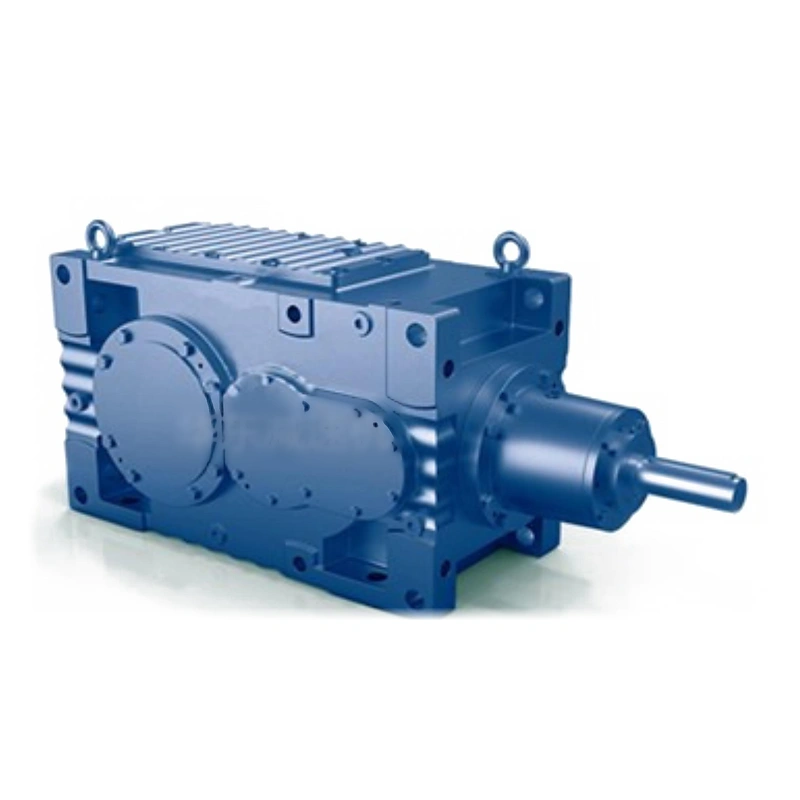
Record most demanding credible recipe and operating temperature; check rated torque against the full process curve; average recipe power may hide a high startup or near-gel condition.
Calculate impeller acceleration
The motor must accelerate rotor, shaft and process-related inertia; large slow impellers can demand substantial transient torque when speed ramps quickly.
Normal running power does not capture startup inertia; estimate coupled inertia and required acceleration time.
Include shaft and process loads in the transient calculation; verify allowable peak gearbox torque with the motor and control; short ramp settings may create unnecessary mechanical shock.
Define output torque and speed
A mixer may need slow shaft motion while the motor operates at higher speed; the required output rpm and continuous N m determine the reduction choice.
Selecting a nominal ratio without actual loaded motor rpm creates error; record process minimum and maximum operating speeds.
Use the motor torque-speed data at those commanded conditions; select ratio and rated output torque for every recipe state; a gearbox with a suitable nameplate power can still operate at wrong impeller speed.
Consider process-induced axial force
Impeller hydrodynamics and gravity can impose thrust along a vertical shaft; a vertical agitator might load the gearbox output bearing even if the shaft transmits torque normally.
External thrust is not necessarily included in nominal gear capacity; estimate upward and downward axial loads over the process envelope.
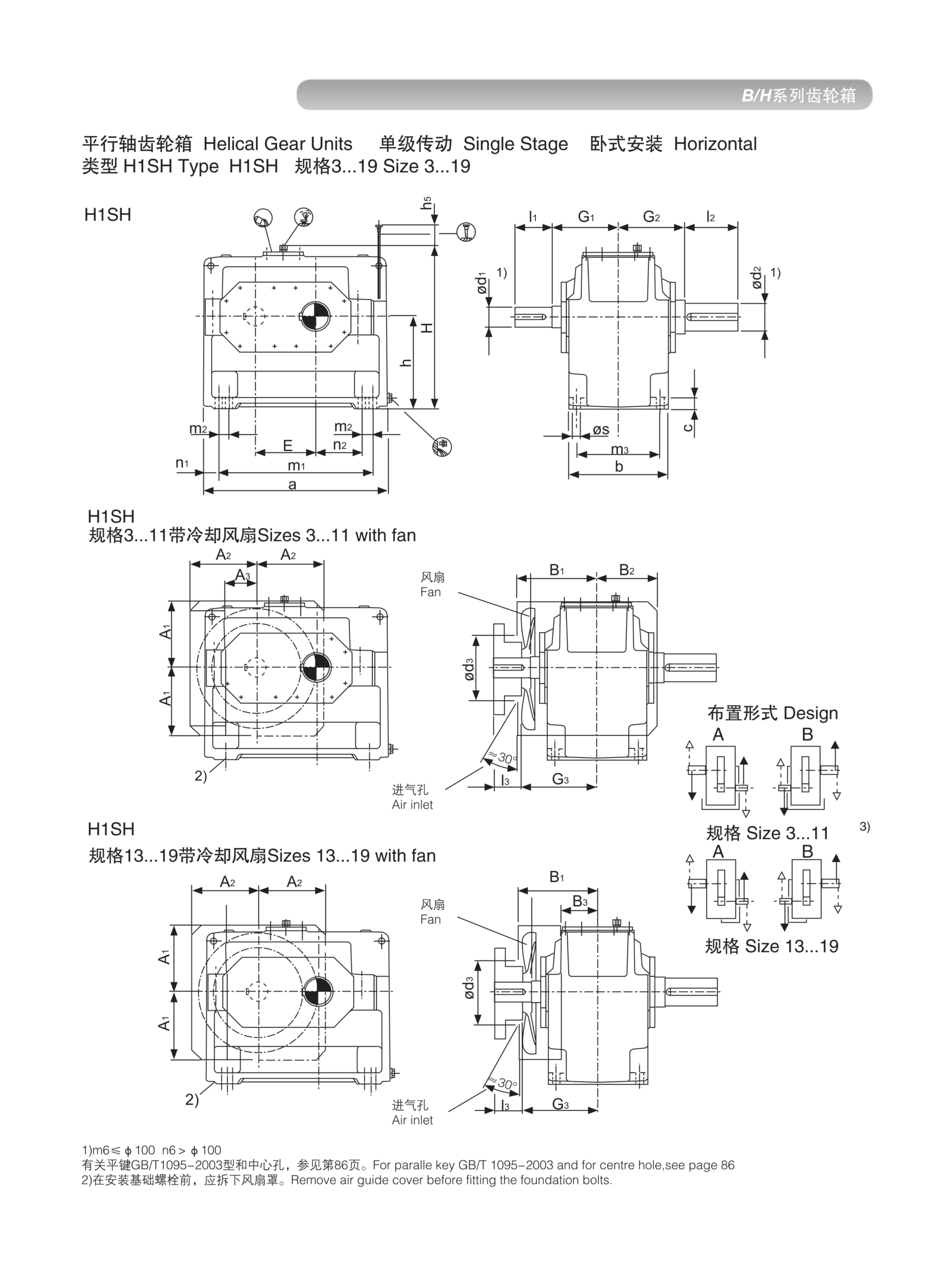
Provide thrust directions, shaft positions and operating rpm; request allowed combined Fr and Fa from the maker; omitted thrust can reduce bearing life despite correct torque sizing.
Plan separate impeller bearings
A long mixing shaft may need stable support against bending and vibration; supporting the whole agitator with a gearbox output alone may be inappropriate.
A heavy impeller can overload an otherwise correctly rated reducer; draw external bearing positions and shaft bending load.
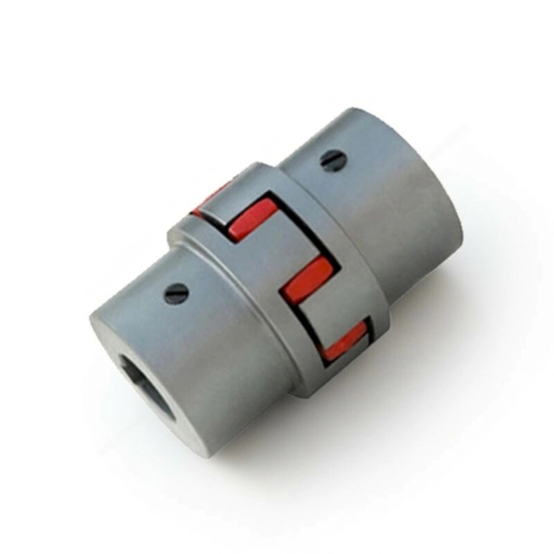
Coordinate fixed or floating supports and seals with the gearbox interface; approve the complete shaft bearing design; an isolated gearbox selection cannot certify the whole mixer rotor.
Supporting the whole agitator with a gearbox output alone may be inappropriate. A heavy impeller can overload an otherwise correctly rated reducer. Examine the agitator reducer sizing layout example. Coordinate fixed or floating supports and seals with the gearbox interface. Approve the complete shaft bearing design.
Assess vapor and washdown
Vessel-top drives can face chemical vapors, splashes or frequent cleaning; a top-mounted reducer may have an upward output seal near wash liquid.
A generic motor protection grade does not prove gear output sealing; describe chemicals, cleaning method and area classification.
Request sealing and material evidence for the exact assembly; select accessories validated for actual process exposure; corrosion and lubricant contamination can become more important than ratio.
Confirm vertical oil routing
The motor and gearbox may be vertical over the vessel rather than horizontal beside it; upper bearings may require specific lubrication within the proposed construction.
A default horizontal fill is not safe to assume; submit installation axis directions and filler access locations.
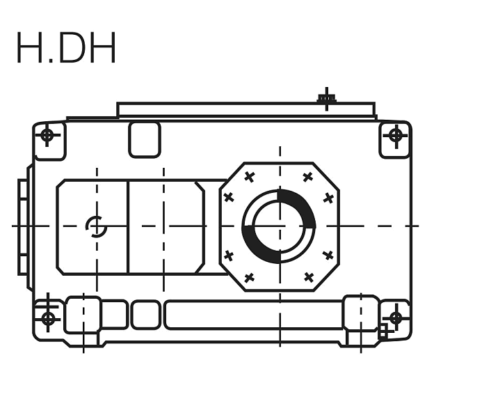
Check approved oil quantity, bearing lubrication and breather position; authorize use only in the supported mounting code; oil-level mistakes are difficult to correct after a mixer is built.
Provide lifting and service clearance
Heavy top-mounted gearmotors may need overhead removal through a limited platform; a maintenance crew might lack room to withdraw the motor or shaft coupling.
A drive that fits may be impossible to replace without vessel shutdown; design access for lifting, isolation and seal replacement.
Measure roof opening, platform and hoist reach; include approved maintenance access in the equipment layout; unplanned extraction can cause significant lost batch time.
Illustrative engineering scenario: A vessel mixer with changing fluid viscosity and shaft thrust
Consider a top-entry mixer that processes a liquid which becomes much more viscous during the initial cooling stage. Normal steady operation may require a modest input power, but cold startup and a fast acceleration ramp can place greater demand on the geartrain. The process engineer collects motor current and torque estimates for the hardest credible batch, not only for a convenient warm run. The mixer shaft also has substantial rotating inertia. A quick start increases acceleration torque, which may need to be compared with an intermittent gearbox capacity separately from the continuous operating torque. If the formulation or impeller diameter changes later, the original load record must be revisited rather than assumed still valid.
The vessel uses a vertical shaft. Process hydrodynamics can produce upward or downward thrust, depending on impeller geometry and flow direction. That force is not the same as reducer output torque. The mechanical designer draws the impeller shaft, vessel support bearings, seals and gearbox output connection, labeling which component carries axial load. The gearbox maker is asked to confirm permissible external Fr and Fa at the relevant position and speed. If the machine has a separately supported agitator shaft, the coupling is checked for misalignment and thermal movement rather than being used to solve an unstable bearing layout.
A platform above the vessel carries the motor and reducer. The mounting position must be approved for oil level and upper bearing lubrication. Vapor exposure, cleaning agents and the possibility of liquid entering an upward-facing connection require a separate environmental review. A general coating or protection statement cannot substitute for documentation of the exact delivery configuration. The design reserves lifting height and safe withdrawal space for the motor, seals and coupling so routine repairs do not require dismantling major vessel structure.
The accepted selection includes a duty envelope by recipe, not a single number. For each operating phase, the engineer records expected rpm, torque, running time and any short peak. The supplier then returns continuous and transient ratings, thermal conditions, applicable shaft-load limits and a dimensioned assembly drawing. During commissioning, the team checks actual startup current, vibration and temperature with the most demanding approved product batch. That test cannot replace missing technical approvals, but it helps establish whether the real machine behaves consistently with the calculations used for purchase.
Process engineers should preserve any assumptions about viscosity and mixer inertia, because they may change with product formulation. If the first production batches produce a higher current or slower ramp than predicted, the duty review should be reopened. A torque margin inferred from a generic service factor cannot replace a confirmed manufacturer transient rating. Recording these deviations is particularly important when the mixing vessel is expected to process several materially different recipes.
Five-stage review for a vessel mixer with changing fluid viscosity and shaft thrust
- Map fluid behavior over the batchCollect viscosity or process resistance versus time and speed. Check rated torque against the full process curve.
- Calculate impeller accelerationInclude shaft and process loads in the transient calculation. Short ramp settings may create unnecessary mechanical shock.
- Consider process-induced axial forceEstimate upward and downward axial loads over the process envelope. Request allowed combined Fr and Fa from the maker.
- Assess vapor and washdownRequest sealing and material evidence for the exact assembly. Corrosion and lubricant contamination can become more important than ratio.
- Provide lifting and service clearanceDesign access for lifting, isolation and seal replacement. Include approved maintenance access in the equipment layout.
Engineering comparison matrix: helical gearbox agitator mixer sizing
| Engineering question | Evidence to collect | Review decision |
|---|---|---|
| Map fluid behavior over the batch | Record most demanding credible recipe and operating temperature. | Check rated torque against the full process curve. |
| Calculate impeller acceleration | Include shaft and process loads in the transient calculation. | Verify allowable peak gearbox torque with the motor and control. |
| Define output torque and speed | Use the motor torque-speed data at those commanded conditions. | Select ratio and rated output torque for every recipe state. |
| Consider process-induced axial force | Provide thrust directions, shaft positions and operating rpm. | Request allowed combined Fr and Fa from the maker. |
| Plan separate impeller bearings | Coordinate fixed or floating supports and seals with the gearbox interface. | Approve the complete shaft bearing design. |
| Assess vapor and washdown | Request sealing and material evidence for the exact assembly. | Select accessories validated for actual process exposure. |
Frequently Asked Questions
Why is mixer starting torque different from normal running torque?
Does a mixer gearbox output bearing carry impeller thrust?
Can a horizontal helical gearbox be used directly above a vessel?
What should a mixer gearbox quotation include?
What makes a final review credible for a vessel mixer with changing fluid viscosity and shaft thrust?
Upper bearings may require specific lubrication within the proposed construction. When comparing actual mounting geometry, use the agitator reducer sizing configuration options. Check approved oil quantity, bearing lubrication and breather position.
Design access for lifting, isolation and seal replacement. For an engineering quotation that records the open conditions, contact the technical team about agitator reducer sizing. Include approved maintenance access in the equipment layout.
Engineering sources for Helical Gearbox Sizing for Agitators and Industrial Mixers
For the helical gearbox sizing for agitators and industrial mixers workflow, consult these reference documents alongside the actual model installation manual:
- Helical Gearbox Sizing for Agitators and Industrial Mixers: SEW-EURODRIVE, Basic calculation process (analysis).
- Helical Gearbox Sizing for Agitators and Industrial Mixers: SEW-EURODRIVE, Application-specific service factor (interface review).
- Helical Gearbox Sizing for Agitators and Industrial Mixers: SKF, Bearing App documentation (acceptance checks).