
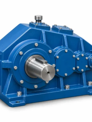
Audible noise is evidence to investigate, but fault location depends on whether the sound tracks speed, torque or the machine structure.
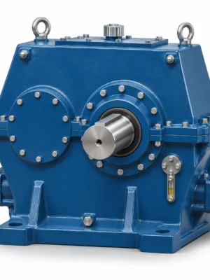
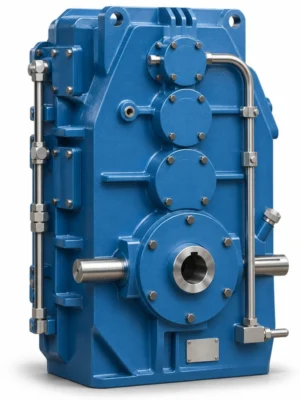
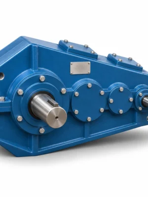
EP-QJY3 Three-Stage Hardened Crane Gear Reducer is specified for three-stage torque buildup and higher reduction. The QJY3 crane gear reducer provides a three-stage arrangement for situations requiring a greater speed reduction than a two-stage layout would conveniently deliver. The family overview lists 20–100 nominal ratios and 170–800 mm centre distances. Those ranges describe the catalogue family, not every available pair of size and ratio. The key purchasing question is how much output torque is required at the actual output speed, including the load events that occur when the crane begins moving, reverses or brakes.
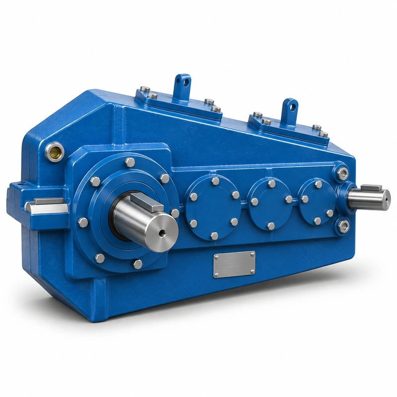
In a crane system, a high ratio changes how the motor, gearbox and connected brake work together. It can allow a higher-speed motor to drive a lower-speed mechanism, but output shaft acceleration and the inertia reflected through the gearing need evaluation. A gearbox selected for steady hoisting torque may see substantially different demands during repeated starts. Include the control mode and the driven machine inertia when developing an EP-QJY3 configuration.
QJY3 machine-matching framework
Mechanical acceptance and machine fit
For an EP-QJY3 installation, the main decision concerns three-stage torque buildup and higher reduction. Comparing real output ratios matters when several crane drives share a rail, load or braking schedule. The best starting point is the actual machine arrangement, the operating load and the requested output speed.
Select
Confirm the true mechanical work point for QJY3 Crane Gear Reducer: input speed, demanded output torque and the dynamic events that govern component loading.
Measure
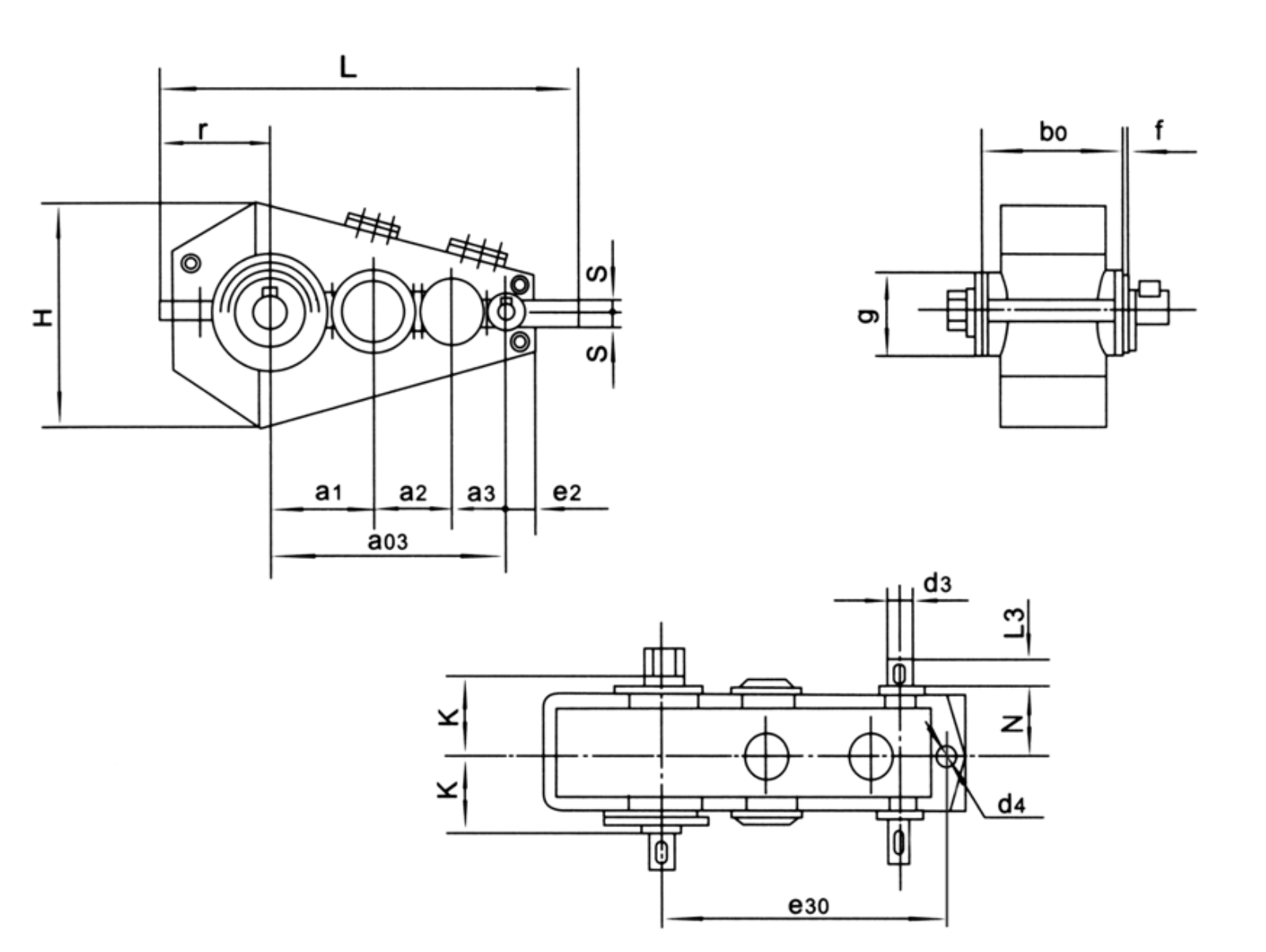
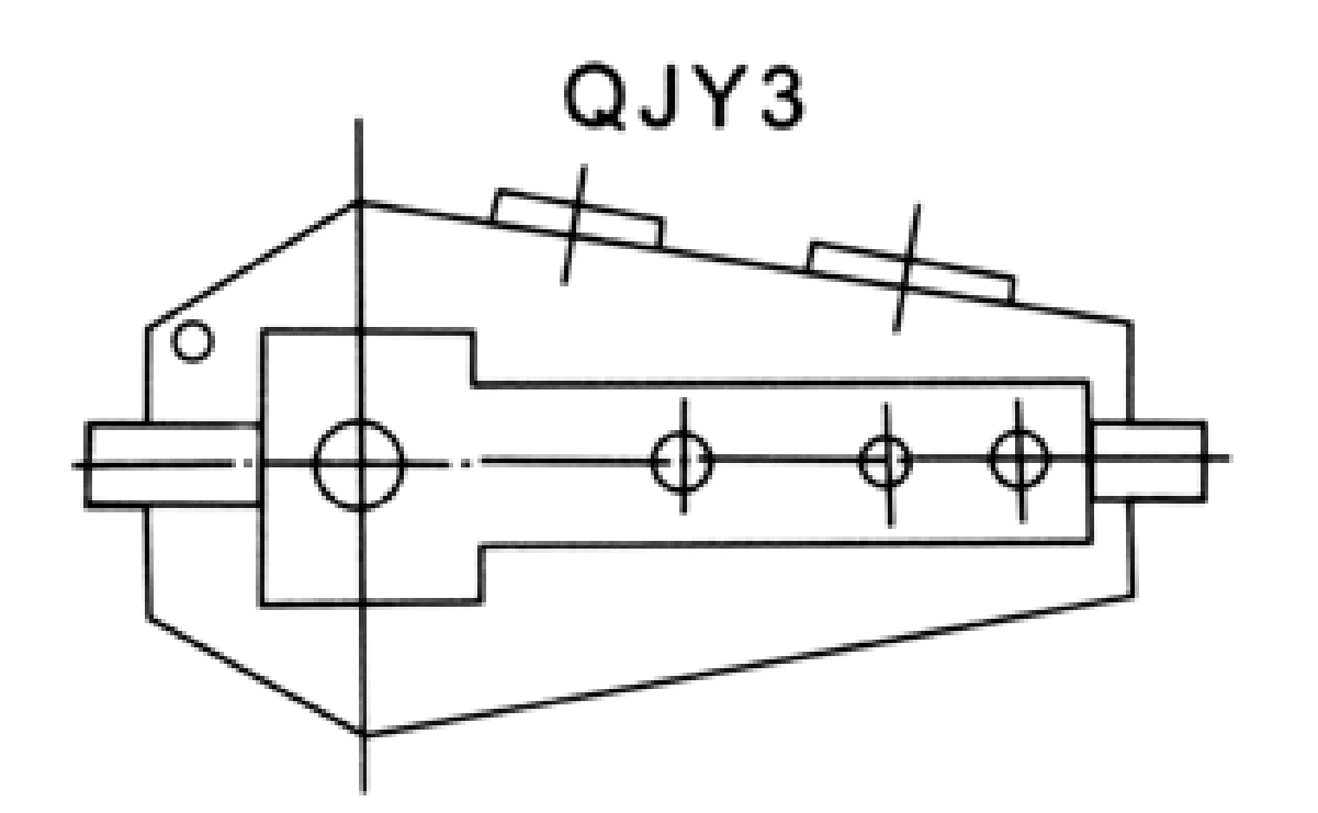
Use the QJY3 dimensional drawing to validate the installation envelope, shaft interfaces, mounting features and clearances on the actual machine.
Integrate
Match the selected drive with the connected motor, brake, coupling and supporting crane structure. Treat fit and control as one application.
Maintain
Plan access for lubrication, seals, inspection and removal. A compatible gearbox should also be practical to service after the crane is installed.
Reducing hoist drum speed
When the motor must run near its efficient speed but the drum requires lower rpm, the 20–100 ratio family can be screened. The final choice requires torque at the drum, system braking details and an evaluation of frequent starting duty.
Three-stage equipment and operating context
- Heavy crane hoisting drives requiring lower shaft speeds: describe the working load and mechanical interface before defining the reducer or gearmotor variant.
- Material-handling machinery with frequent reversing duty: describe the working load and mechanical interface before defining the reducer or gearmotor variant.
- Modernization where original reducer ratios exceed two-stage options: describe the working load and mechanical interface before defining the reducer or gearmotor variant.
Three-stage duty and interface specification
QJY3 specification and model identification
QJY3 Crane Gear Reducer selection is defined by the combination of family construction, operating point and machine interfaces. The following data identifies the documented product family; a specific configuration must still be checked against its dimensional drawing and duty schedule.
| Parameter | Series-level reference |
|---|---|
| Gear stages | 3 |
| Nominal transmission ratio | 20–100 |
| Family centre-distance range | 170–800 mm |
| Family applicable power span | 2.9–1801 kW in family overview; not per unit |
| Related layouts | QJY23 compact; QJYD3 foot-mounted; QJYA3 hollow-shaft |
The nominal centre-distance schedule below covers 13 named frame entries. It is a series index, not a statement that every combination of nominal ratio, shaft end and mounting exists at every size.
| Frame reference | Nominal centre distance | Ordering condition |
|---|---|---|
| Nominal centre a1 = 170 mm | 170 mm | Confirm ratio, interface and load rating for the requested version |
| Nominal centre a1 = 200 mm | 200 mm | Confirm ratio, interface and load rating for the requested version |
| Nominal centre a1 = 236 mm | 236 mm | Confirm ratio, interface and load rating for the requested version |
| Nominal centre a1 = 280 mm | 280 mm | Confirm ratio, interface and load rating for the requested version |
| Nominal centre a1 = 335 mm | 335 mm | Confirm ratio, interface and load rating for the requested version |
| Nominal centre a1 = 370 mm | 370 mm | Confirm ratio, interface and load rating for the requested version |
| Nominal centre a1 = 400 mm | 400 mm | Confirm ratio, interface and load rating for the requested version |
| Nominal centre a1 = 450 mm | 450 mm | Confirm ratio, interface and load rating for the requested version |
| Nominal centre a1 = 500 mm | 500 mm | Confirm ratio, interface and load rating for the requested version |
| Nominal centre a1 = 560 mm | 560 mm | Confirm ratio, interface and load rating for the requested version |
| Nominal centre a1 = 630 mm | 630 mm | Confirm ratio, interface and load rating for the requested version |
| Nominal centre a1 = 710 mm | 710 mm | Confirm ratio, interface and load rating for the requested version |
| Nominal centre a1 = 800 mm | 800 mm | Confirm ratio, interface and load rating for the requested version |
Operating envelope
List the actual input rpm under normal control, maximum continuous output torque, starting torque and number of accelerations per operating hour. For crane hoisting, state the duty/load classification and whether the mechanism operates at rated load for extended periods. These factors influence thermal and mechanical selection.
Bearing and shaft loads
Check how the output connects to the drum or wheel shaft. A flexible coupling normally creates a different bearing load from a directly mounted pinion or sheave. State overhang distance and all external forces when an output shaft is loaded. Do not infer permitted radial load from the diameter of the visible shaft.
Stage arrangement and space
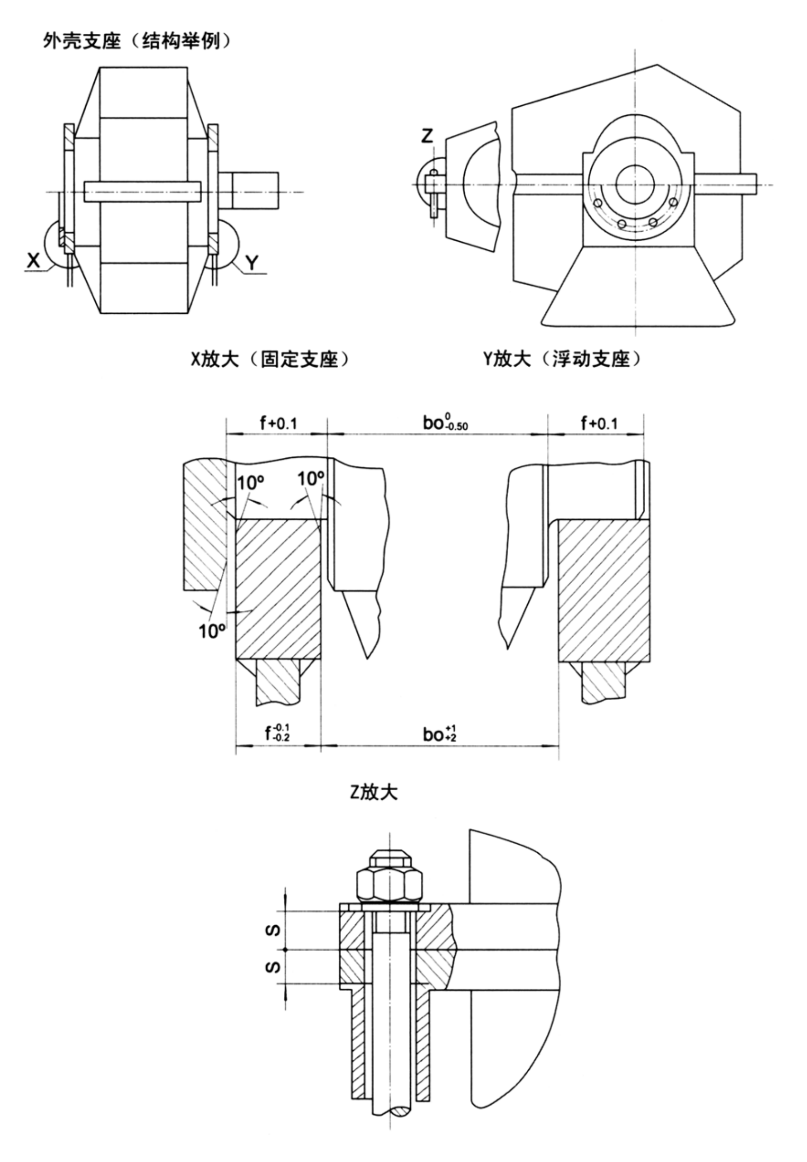
A three-stage reducer is longer or configured differently from the two-stage family; mounting and input-output relationships should be verified using the QJY3 outline. The reduced speed at the output does not guarantee a smaller overall machine arrangement, because supports, couplings and guards still determine the final footprint.
Lubrication and cooling
Three mesh stages produce heat at their operating load and speed. Review lubrication method, installed orientation, ambient temperature and daily running time. A gearbox housing may fit the crane but still need a service arrangement suitable for the environment and access available on site.
Alignment and commissioning
Keep mounting surfaces clean and check for mechanical distortion before tightening the gearbox. Verify input and output alignment against the approved assembly sketch, then perform a staged commissioning test. Trend temperature and vibration at a repeatable load point rather than relying solely on a short no-load run.
Ratio confirmation
The nominal ratio is a selection label. Use the actual ratio from the confirmed gear train for speed-sensitive machines, including synchronized travel axes or multi-drive equipment. If another reducer remains installed on the same crane, compare output speed under the same motor frequency before accepting a mixed replacement.
Comparison with mount variants
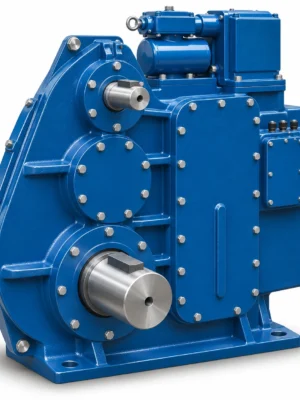
The QJY3 basic design must not be silently substituted with QJYD3 foot-mount or QJYA3 hollow-shaft descriptions. These variants have different interface drawings and different installation tasks. Buyers should request a drawing matching the actual construction ordered, not merely a family illustration.
- Three-stage ratio requirement: include the appropriate drawing, measured value, operating cycle or connection detail.
- Single or multiple gearbox synchronization: include the appropriate drawing, measured value, operating cycle or connection detail.
- Rated and start-up output torque: include the appropriate drawing, measured value, operating cycle or connection detail.
- Hoist or travel duty class: include the appropriate drawing, measured value, operating cycle or connection detail.
- Input/output shaft interface: include the appropriate drawing, measured value, operating cycle or connection detail.
- Mount orientation and space envelope: include the appropriate drawing, measured value, operating cycle or connection detail.
- Daily operation period: include the appropriate drawing, measured value, operating cycle or connection detail.
- Motor/brake control method: include the appropriate drawing, measured value, operating cycle or connection detail.
Commercial enquiry for the QJY3 series
Ever Power can discuss model identification, interface drawings and practical order quantities for the QJY3 Crane Gear Reducer. Confirmed product configuration, lead time and delivery terms belong in the quotation. Trial and mixed-model requests can be assessed against the total order value.
To compare related drive families, explore the industrial drive product range. The company overview explains the supplier context for engineering and procurement enquiries.
Frequently asked questions about EP-QJY3
Can the QJY3 replace a QJY2 if the motor power matches?
Not automatically. The gear stages and nominal ratio ranges differ, and matching motor power does not establish equal output speed, shaft fit or mounting. Confirm the complete operating point and drawings.
What input data determine a QJY3 size?
Provide motor speed, required output speed, applied torque, load spectrum, start/reverse frequency, centre-distance preference and shaft loads. Available ratings have to be checked for the selected gear configuration.
Should the exact ratio be used for multi-drive cranes?
Yes. Compare actual ratios and resulting speeds if two or more mechanisms are synchronized. A nominal catalogue ratio should not be used as proof of speed matching.
Can a distributor combine several reducer models in a trial shipment for EP-QJY3?
Yes, mixed model quantities may be assessed together against an approximate USD 1,500 minimum order value. A new distributor can ask for 1–5 trial pieces when practical. Very small requests of 1–2 units may be accepted, but should be priced as a small production batch rather than standard-volume procurement. For this product, quote preparation should also address three-stage torque buildup and higher reduction and the requested quantity.
When could an engineered crane reducer be delivered for EP-QJY3?
The schedule depends on the confirmed drawing and production route: standard products typically require 10–25 working days, custom components 20–45 and project-scale equipment 45–120. These are planning ranges, not a promised ship date. Normal trade terms include EXW, FOB, CIF and DAP, with FCA, CFR, CPT, CIP and DDP subject to agreement. Schedule confirmation follows review of the QJY3 interface and duty requirements.
Request a three-stage transmission review
Have an engineer compare the drive speeds, expected output forces and drawing envelope for your EP-QJY3 installation. Send the assembly requirements and any existing reducer details.