DC Drum Series Crowned Gear Coupling — For Crane Hoist Drum Connections
The only crowned gear coupling that simultaneously transmits torque and bears radial drum loads through an integral self-aligning spherical bearing. Compact, stable, and safety-indicated — the standard crane hoist drum coupling solution.
Torque Range
4 – 800 KN·m
Radial Load
14.5 – 450 kN
Working Temp
-25 to +80 deg C
Drum Connection
Flange or Direct
Product Overview
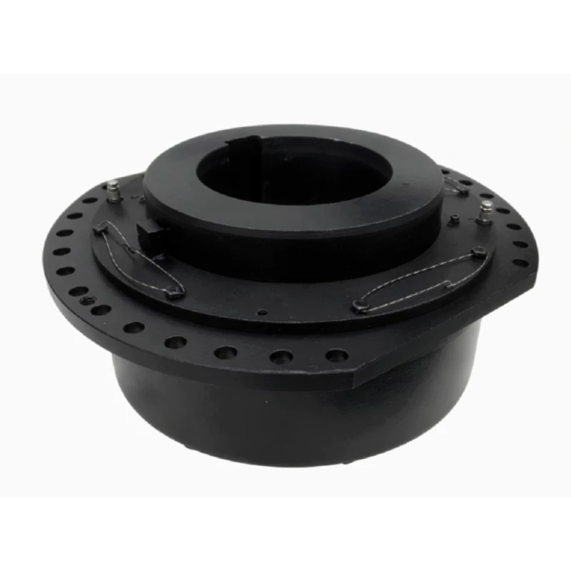
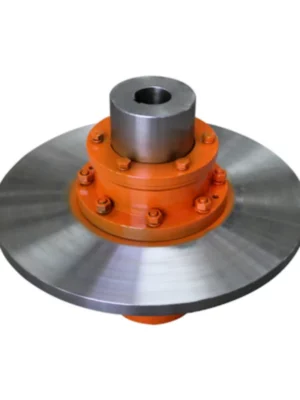
The DC drum series crowned gear coupling is a purpose-built flexible coupling for connecting crane hoist drums to gearbox reducer output shafts in hoisting machinery. It is the only coupling type in the industrial gear coupling family that simultaneously performs two functions: transmitting drive torque from the gearbox to the drum, and bearing the radial load generated by the drum weight, wire rope tension, and operational dynamic forces — all through a single compact unit without requiring a separate outboard drum support bearing.
This dual function is made possible by the DC's integral self-aligning spherical bearing face — a precision-machined outer spherical surface on the loading ring that mates with a concave inner bearing surface in the outer sleeve, forming a self-aligning contact that carries radial forces directly through the coupling body to the gearbox housing. The result is a simpler crane hoist structure: fewer components, less weight, reduced installation complexity, and a single maintenance point for both the coupling and the drum radial support.
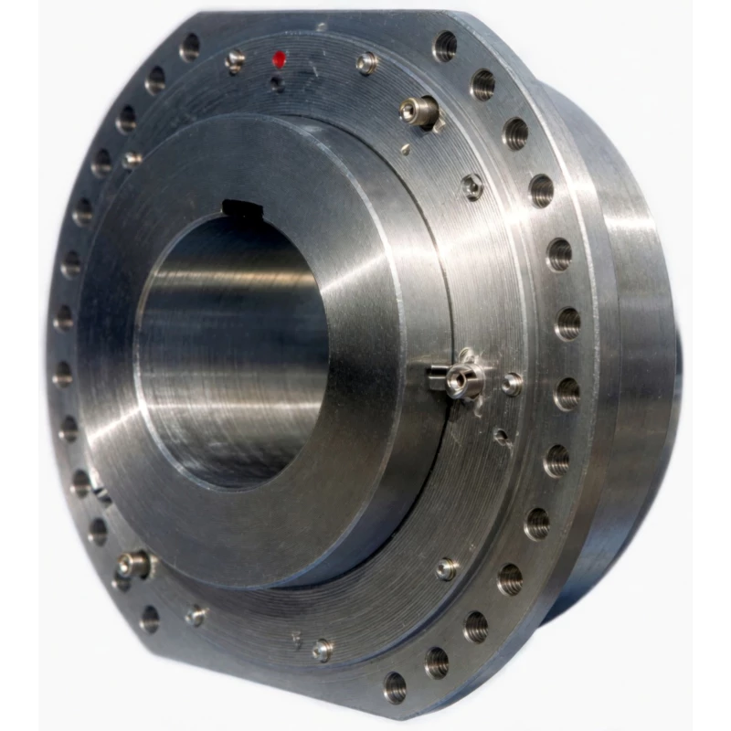
Additional features that make the DC the preferred crane hoist drum coupling include a graduated wear pointer for visible maintenance scheduling without disassembly, two drum connection modes (middle flange and direct), a lubrication nipple for routine greasing, a vent nipple to prevent pressure build-up, and full compatibility with standard shaft-extended gearboxes.
Technical Definition and Working Principle
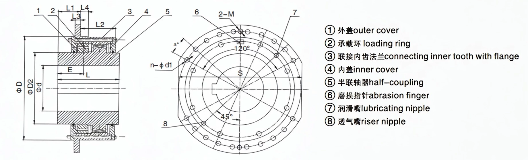
Component Architecture — Five Key Elements
The DC coupling consists of five primary structural components, each with a specific function in the torque transmission and radial load bearing system.
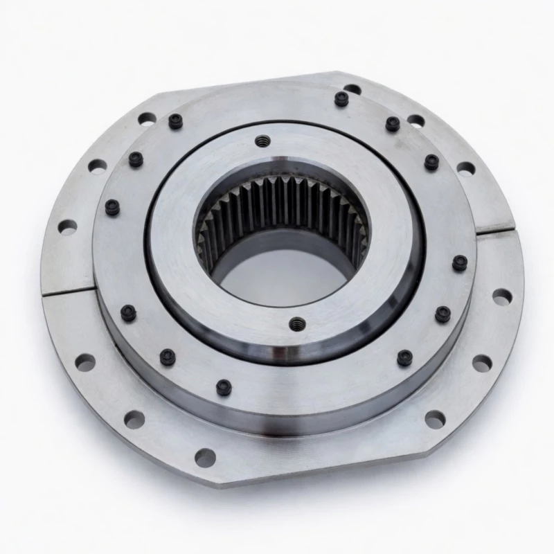
- Half-coupling with crowned teeth — The gearbox-side component. Mounts on the gearbox output shaft bore with standard keyway fit. The hub carries externally crowned gear teeth that mesh with the inner gear ring of the outer sleeve to transmit torque. The crowned tooth geometry provides angular, radial, and axial misalignment compensation.
- Outer sleeve with connecting flange and inner gear ring — The drum-side component. Connects to the hoist drum via bolted flange connection (middle flange or direct mode). The inner gear ring meshes with the half-coupling's crowned teeth for torque transmission. The inner concave bearing surface mates with the loading ring's outer spherical face to form the radial load path.
- Loading ring with outer spherical surface — The critical radial load element. The precisely machined outer spherical face of the loading ring contacts the matching concave surface in the outer sleeve, forming a self-aligning ball bearing that carries all radial loads from the drum through the coupling to the gearbox housing. This is the feature that eliminates the need for a separate drum pillow block bearing.
- Inner and outer covers plus seals — Protect the internal components, retain lubricant, and exclude contaminants. The seal design is critical for maintaining lubrication in the radial load bearing zone throughout the coupling's service life.
- Wear pointer, lubrication nipple, and vent nipple — Service and safety accessories. The wear pointer provides visual, tool-free wear status indication. The lubrication nipple allows routine greasing. The vent nipple prevents internal pressure build-up during operation and thermal cycling.
How the Crowned Tooth Transmits Torque Under Combined Loading
The DC's gear tooth mesh is a standard two-mesh crowned-tooth arrangement. The half-coupling's externally crowned teeth engage the outer sleeve's internal straight teeth, transmitting drive torque while accommodating the angular and radial misalignment between the gearbox output shaft and the drum axis. The crowned tooth profile produces a self-centring Hertzian contact ellipse that remains near the tooth centre regardless of misalignment angle, eliminating the destructive edge loading of a straight-tooth coupling under the same conditions.
On crane hoist drives, the coupling must transmit torque under conditions that change with each lift cycle: starting torque peaks of 2–4× rated torque during motor acceleration, running torque during the lift, and torque reversals during lowering and braking. The DC's crowned tooth distributes all of these torque events as Hertzian contact ellipses, extending tooth service life significantly compared to straight-tooth designs.
The Self-Aligning Spherical Bearing — How Radial Loads Are Carried
The radial load path in the DC coupling is entirely separate from the torque transmission path. The drum's weight and wire rope tension are transmitted from the outer sleeve into the loading ring's spherical face contact, and from the loading ring through the half-coupling hub into the gearbox output shaft bearing. The spherical contact geometry allows the outer sleeve and connected drum to align itself automatically relative to the gearbox shaft axis, accommodating angular misalignment without creating bending moments at the shaft or gear teeth.
This self-aligning capability is critical for crane hoist drums: during operation, the drum deflects under the combined weight of the wire rope and hook load, and the angular position of the drum axis relative to the gearbox axis changes slightly with load. The DC's spherical bearing face accommodates this angular change continuously without stress concentration.
How DC Differs from Standard Gear Couplings and Other Coupling Types
| Feature |
DC (this product) |
Standard WG Gear Coupling |
Jaw Coupling |
Disc Coupling |
| Torque Transmission |
Yes — crowned gear teeth |
Yes — crowned gear teeth |
Yes — elastomer |
Yes — disc pack |
| Integral Radial Load Bearing |
Yes — spherical loading ring, up to 450 kN |
No — separate bearing required |
No |
No |
| Self-Aligning Capability |
Yes — spherical face self-aligns under load |
Misalignment only via gear mesh |
Limited |
Limited |
| Wear Indicator |
Yes — calibrated wear pointer |
No |
No |
No |
| Drum Connection Flange |
Yes — direct or flange mode |
No drum flange |
No drum flange |
No drum flange |
| Intended Application |
Crane/hoist drum-to-gearbox connection only |
General horizontal shaft drives |
General light-medium duty |
General medium-high speed |
Specifications & Size Matrix — DC01 to DC10
All DC coupling sizes operate at 200 RPM. Each size group has an A variant (standard torque and radial load) and a B variant (higher torque and radial load, larger shaft bore and outer diameter). Working temperature range is -25 to +80°C. Dimensions in millimetres, torque in N·m, radial load in N.
DC Series Main Specifications
| Model |
Speed
(rpm) |
Torque T
(N·m) |
Radial Load F
(N) |
Shaft Bore
d H7 (mm) |
Shaft Length
L (mm) |
Outer Dia
D (mm) |
Drum Conn
D3 h6 (mm) |
D2 h9
(mm) |
Bolt Circle
D1 (mm) |
Bolt n-d1
(mm) |
Bolt M |
K1 |
Weight
(kg) |
| DC01A |
200 |
16,000 |
18,000 |
110 |
185 |
400 |
280 |
280 |
360 |
10–18 |
M16 |
5.2 |
80 |
| DC01B |
200 |
22,400 |
25,000 |
125 |
200 |
420 |
310 |
310 |
380 |
10–18 |
M16 |
5.2 |
100 |
| DC02A |
200 |
31,500 |
25,000 |
150 |
225 |
450 |
340 |
340 |
400 |
10–22 |
M20 |
4.7 |
120 |
| DC02B |
200 |
45,000 |
35,500 |
160 |
235 |
510 |
400 |
400 |
460 |
10–22 |
M20 |
4.7 |
150 |
| DC03A |
200 |
63,000 |
50,000 |
200 |
265 |
550 |
420 |
420 |
500 |
10–22 |
M20 |
4.1 |
190 |
| DC03B |
200 |
90,000 |
71,000 |
220 |
290 |
580 |
450 |
450 |
530 |
10–22 |
M20 |
4.1 |
245 |
| DC35A |
200 |
125,000 |
112,000 |
240 |
300 |
620 |
500 |
500 |
560 |
14–22 |
M20 |
3.7 |
330 |
| DC35B |
200 |
160,000 |
140,000 |
260 |
300 |
650 |
530 |
530 |
590 |
14–22 |
M20 |
3.7 |
385 |
| DC04A |
200 |
224,000 |
180,000 |
260 |
300 |
680 |
560 |
500 |
500 |
14–22 |
M20 |
3.4 |
~400 |
| DC04B |
200 |
315,000 |
224,000 |
280 |
310 |
720 |
600 |
530 |
530 |
14–22 |
M20 |
3.4 |
~490 |
| DC05A |
200 |
450,000 |
280,000 |
300 |
340 |
780 |
630 |
530 |
500 |
14–22 |
M20 |
3.0 |
~550 |
| DC05B |
200 |
560,000 |
355,000 |
320 |
350 |
850 |
670 |
580 |
530 |
14–22 |
M20 |
3.0 |
~650 |
| DC55A – DC10B |
200 |
up to 800,000 |
up to 450,000 |
up to 380 |
up to 420 |
up to 1250 |
up to 960 |
up to 880 |
up to 800 |
26–26 |
M24 |
1.8–2.8 |
up to 890 |
Note: DC55A, DC55B, DC65A, DC65B (intermediate sizes between DC05 and DC06), and DC06A through DC10B continue the series to 800 KN·m maximum torque and 450 kN radial load. Contact our engineering team for complete dimensional data for DC55 through DC10 sizes.
Radial Load Compensation Factor K1 by Model
| Model |
DC01 |
DC02 |
DC03 |
DC35 |
DC04 |
DC05 |
DC55 |
DC06 |
DC07 |
DC08 |
DC09 |
DC10 |
| K1 |
5.2 |
4.7 |
4.1 |
3.7 |
3.4 |
3.0 |
2.8 |
2.6 |
2.4 |
2.2 |
2.0 |
1.8 |
Working Condition Factor K2 by Crane Duty Class
| Duty Class |
M2 |
M3 |
M4 |
M5 |
M6 |
M7 |
M8 |
| K2 |
1.00 |
1.12 |
1.25 |
1.40 |
1.60 |
1.80 |
2.00 |
Duty class M2–M8 per GB3811.
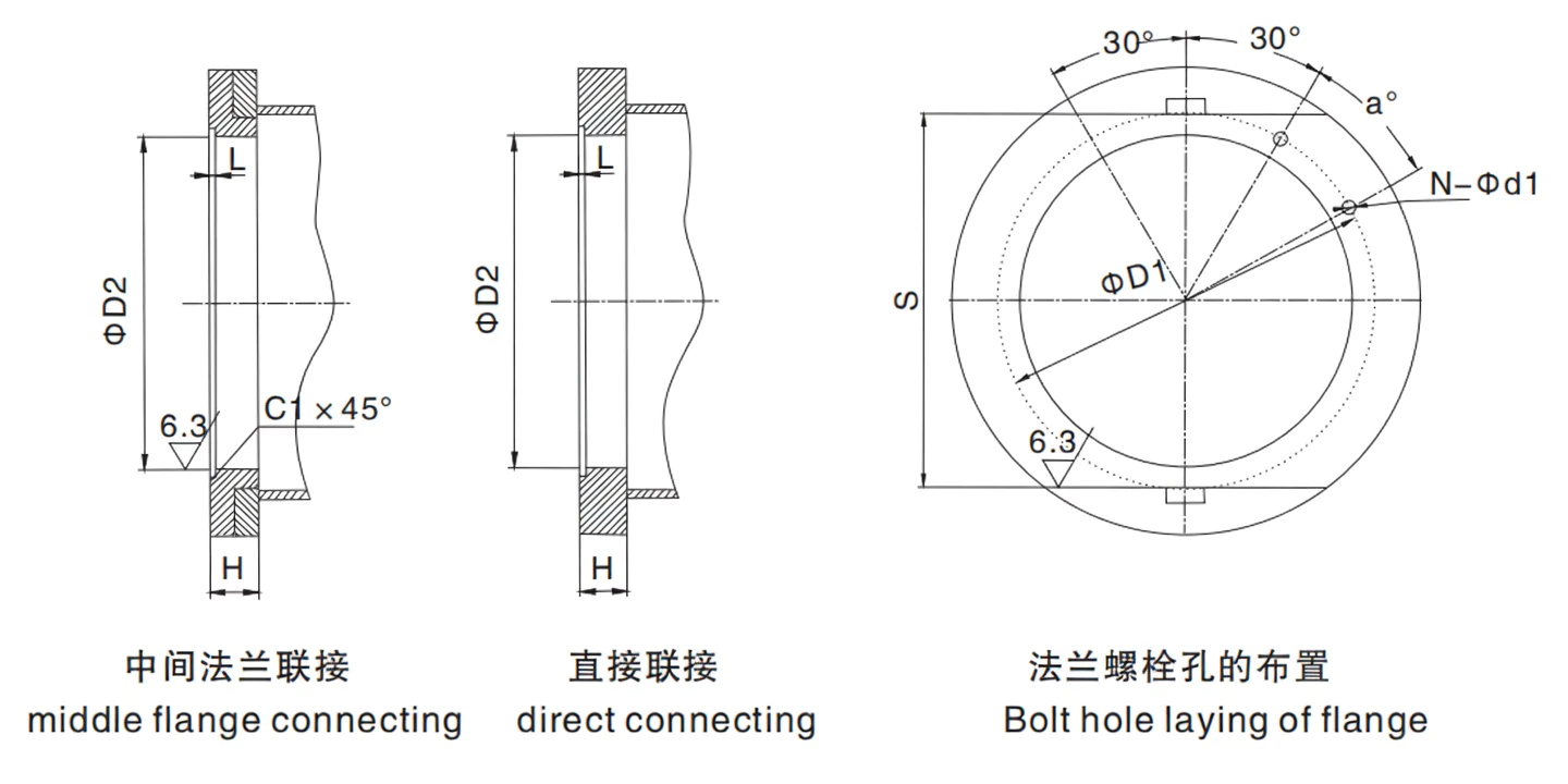
Drum Connection Modes — Middle Flange and Direct Connecting
The DC coupling connects to the hoist drum in two configurations, both using high-strength taper key connections between the drum bore and the coupling outer sleeve. The connection mode is selected based on the drum design and available clearance at the drum end plate.
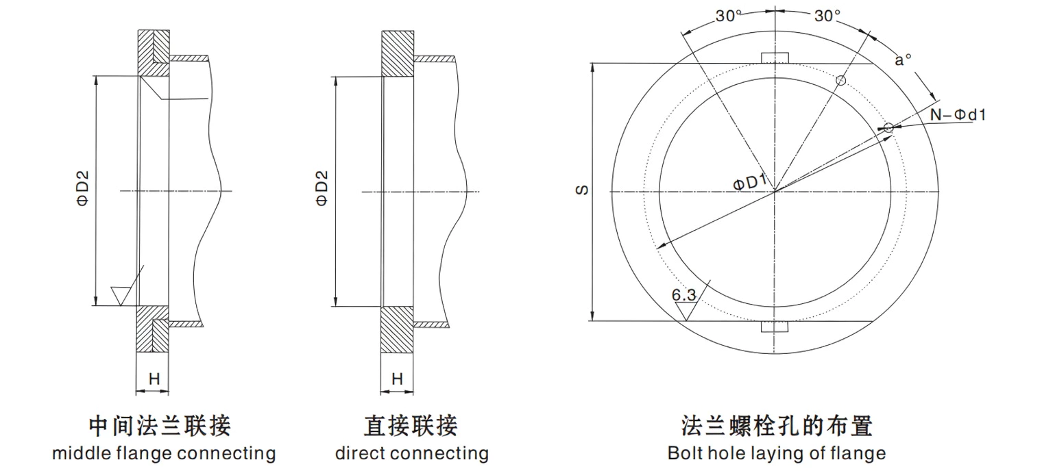
Middle Flange Connecting (middle flange connection)
An intermediate flange plate is bolted between the coupling outer sleeve flange (D2 bore) and the drum end plate. This mode allows adjustment of the axial position between the coupling and the drum, and accommodates drums where the direct bolt circle geometry does not align with the coupling flange pattern. It is preferred when the crane design places the gearbox and drum at a specific axial separation.
Connection hardware: Grade 8.8 bolts per bolt circle specification. Taper key between drum bore and coupling sleeve.
Direct Connecting (direct connection)
The coupling outer sleeve flange bolts directly to the drum end plate without an intermediate flange, producing a more compact installation with fewer components. Direct connecting is preferred for new crane designs where the drum bolt circle diameter (D1) can be specified to match the coupling flange pattern.
Connection hardware: Grade 8.8 bolts per bolt circle specification. Taper key between drum bore and coupling sleeve. Minimum axial clearance C1 required.
DC in the Gear Coupling Family — Where It Fits
The DC is a specialised member of the crowned gear coupling product range. While the WG coupling family covers general industrial shaft-to-shaft drive applications, the DC is purpose-engineered for connecting a hoist drum to a gearbox output shaft while simultaneously bearing the drum's radial load through its integral spherical bearing face.
| Factor |
DC |
WG |
WGP |
WGC |
WGZ |
WGT |
| Standard |
Crane drum spec |
JB/T8854.2 |
JB/T7001 |
JB/T7002-93 |
JB/T7003-93 |
JB/T7004 |
| Integral Radial Load Bearing |
Yes — spherical ring up to 450 kN |
No |
No |
No |
No |
No |
| Drum Connection Flange |
Yes — direct or flange mode |
No |
No |
No |
No |
No |
| Braking Feature |
None (drum itself is the braked component) |
None |
Flat disc — caliper |
None |
Drum — shoe brake |
None |
| Wear Indicator |
Yes — calibrated wear pointer |
No |
No |
No |
No |
No |
| Max Speed |
200 RPM (all sizes) |
Up to 7500 RPM |
Up to 4000 RPM |
Up to 7500 RPM |
Up to 4000 RPM |
Up to 7500 RPM |
| Torque Range |
16 KN·m – 800 KN·m |
0.71–1250 KN·m |
0.71–160 KN·m |
0.71–160 KN·m |
0.71–160 KN·m |
0.71–1250 KN·m |
| Choose When... |
Connecting gearbox to hoist drum; radial load bearing required; drum torque + radial combined |
Standard horizontal shaft coupling, no brake, no drum |
Caliper disc brake required |
Vertical shaft drive |
Shoe brake required |
Long shaft span or axle withdrawal needed |
For applications requiring a brake on the crane drive shaft independently of the hoist drum — for example on crane travel drives — the WGZ (shoe brake) or WGP (caliper disc brake) variants are the correct selections. The DC is the right choice only when the hoist drum itself must be connected to the gearbox output shaft with integral radial load support.
Technical Advantages — Why the DC Crowned Gear Outperforms Conventional Solutions
Longer Service Life Under Shock Loads — Every Lift Is a Shock Event
Every crane lift starts with a torque peak. The DC's crowned teeth distribute this startup peak as a Hertzian contact ellipse — maximum stress near the tooth centre, zero stress at the edges — compared to the full-face edge-concentrated stress of a straight-tooth coupling. In documented industrial applications, DC-type crowned drum couplings demonstrate 4–6× the tooth service life of straight-tooth drum coupling alternatives under the same M7/M8 duty cycle.
Reduced Bearing Loads — Protecting Gearbox Output Shaft Bearings
In a conventional drum drive without a DC coupling, the drum radial load is borne by a separate outboard pillow block bearing requiring precise positioning. In the DC arrangement, the loading ring spherical face carries the drum radial load directly without requiring perfect alignment — the self-aligning spherical geometry accommodates any misalignment automatically. The gearbox output shaft bearing experiences only the torque reaction, not additional bending from drum misalignment, extending gearbox bearing service life by 30–60% in documented comparisons.
Lower Maintenance Frequency — Wear Pointer Plus Lubrication Nipple
The DC coupling provides two complementary maintenance features. The wear pointer allows the coupling's wear state to be assessed visually during routine crane inspection — no disassembly required, no shutdown necessary. This enables condition-based maintenance scheduling, typically extending the average coupling replacement interval by 40–60% compared to time-based programmes. The lubrication nipple allows routine greasing during any crane inspection with standard equipment.
Compact Design — Structural Simplification and Weight Reduction
Compared to a conventional drum drive with a separate coupling plus outboard pillow block bearing, the DC reduces component count by eliminating the outboard bearing, its housing, mounting bracket, lubrication system, and alignment hardware. In documented crane design comparisons, replacing the conventional arrangement with the DC reduces the total hoist mechanism length by 150–250 mm and reduces the total component weight of the drum support system by 20–35%.
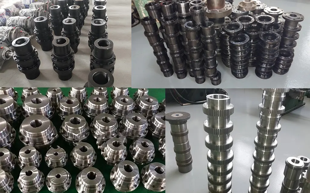
Manufacturing & Quality Assurance
Manufacturing Process
DC couplings are manufactured from precision castings and forged steel blanks. The half-coupling hub is forged from 42CrMo4 alloy steel and the crowned gear teeth are CNC hobbed to DIN Class 7 accuracy. Tooth flanks are carburised and quenched to HRC 58–62 surface hardness. The loading ring is precision cast or forged, with the outer spherical surface finish-machined to Ra 1.6 μm for correct spherical bearing contact.
The outer sleeve is machined from forged or cast alloy steel. The inner gear ring is broached or hobbed to the same DIN Class 7 accuracy as the half-coupling teeth. The connecting flange bolt holes are drilled and reamed to H9 tolerance. All bores are finished to H7 tolerance.
Each complete DC coupling assembly undergoes a system inspection before dispatch: coupling body concentricity, spherical face contact verification, axial float measurement, bolt hole positional accuracy, and wear pointer baseline verification are all measured and recorded.
Quality Control Flow
STEP 1
Material Inspection & Chemistry
STEP 2
CNC Hobbing, Bore, Spherical & Flange Machining
STEP 3
Carburising & Quench Hardening
STEP 4
CMM, Spherical Face, Tooth Profile & Hardness
STEP 5
System Assembly, Wear Pointer Set & Pack
Certifications
ISO 9001:2015 quality management certification covers all DC coupling manufacturing and inspection operations. CE marking applies to applicable sizes. Every shipment includes material mill certificates with heat traceability for all major components, heat treatment records, Rockwell hardness test certificates, and spherical face contact verification records.
Why Source Your DC Couplings from RP?
Engineering Support for Selection and Calculation
Selecting a DC coupling requires the combined torque and radial load calculation (To check and Fr check per catalogue). Our engineers perform this calculation as a standard part of every DC order, providing confirmed To and Fr documentation for crane OEM engineering records.
Flexible MOQ — Single Units to Project Quantities
DC couplings are available from a single unit for replacement or repair projects through to full new-build crane project quantities. Standard sizes ship within 15–20 working days ex-works. Custom shaft bore diameters or non-standard connection flange bolt patterns add 5–10 working days.
OEM and Custom Configurations
Non-standard shaft bores, modified connection flange bolt patterns, marine-grade hardware for salt-air environments, elevated temperature seal materials for metallurgical applications, and special surface treatments for corrosive environments are all achievable to customer drawings. Contact us with your drawing.
Complete Gear Coupling Range — One Supplier
RP supplies DC drum couplings alongside the complete WG coupling family and other industrial coupling types. Crane projects requiring DC couplings on hoist drums and WGZ or WGP couplings on travel drives are served by one engineering team and one procurement channel.
Case 3: New-Build Heavy Fabrication Workshop Crane — Victoria
Customer Profile: A heavy steel fabrication company commissioning a new 80-tonne double-girder overhead travelling crane for heavy beam and plate handling in an M5 service class application.
Challenge: The crane designer's original specification included a conventional drum coupling plus outboard bearing arrangement that required a 600 mm longer drum assembly than the DC alternative — creating structural interference with the intended crane bay column grid. The designer needed to reduce the hoist mechanism length by at least 400 mm without compromising torque and radial load capacity.
Solution: We supplied 2× DC05A couplings (450,000 N·m, d=300 mm, middle flange connecting) — the DC's elimination of the outboard bearing assembly reduced the drum end connection length by 430 mm, resolving the interference issue.
Result: The crane was commissioned on schedule within the original bay column grid without structural modification. After 18 months of operation at approximately 15–20 lifts per day, the wear pointers on both couplings show approximately 20% wear — consistent with the projected 5–7 year replacement interval for M5 duty.