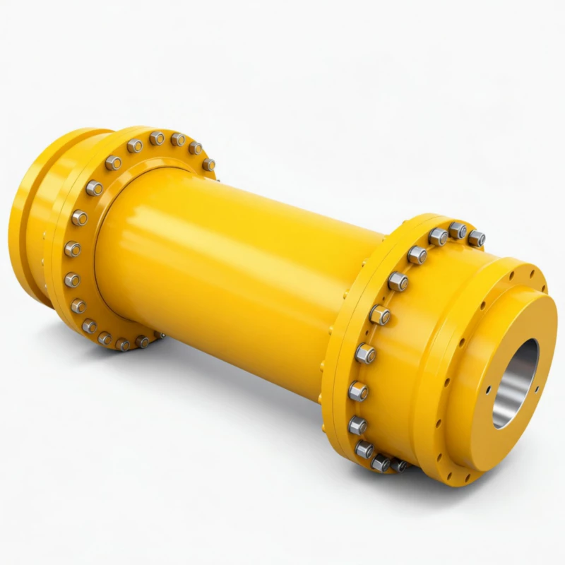
WGT Drum Shape Gear Coupling with Intermediate Sleeve — High Rigidity, Axle Withdrawal
The WG-family solution for long-span shaft connections and axle withdrawal maintenance access. A removable intermediate sleeve spans the gap between two crowned-tooth coupling halves — withdraw the sleeve without moving either shaft. 24 sizes, widest torque range in the WG family.
Torque Range
710 N·m – 1,250,000 N·m
Sleeve Length H
Customisable
Product Overview
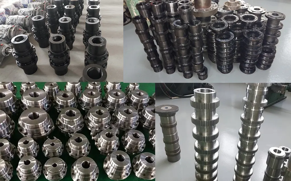
The WGT drum shape gear coupling with intermediate sleeve is the member of the WG coupling family selected when two drive shafts are separated by a distance too large for a standard compact coupling, or when maintenance access requires axle withdrawal capability — the ability to remove the intermediate sleeve from between the two coupling halves without disturbing either shaft or its alignment.
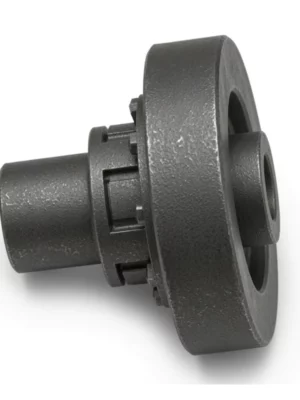
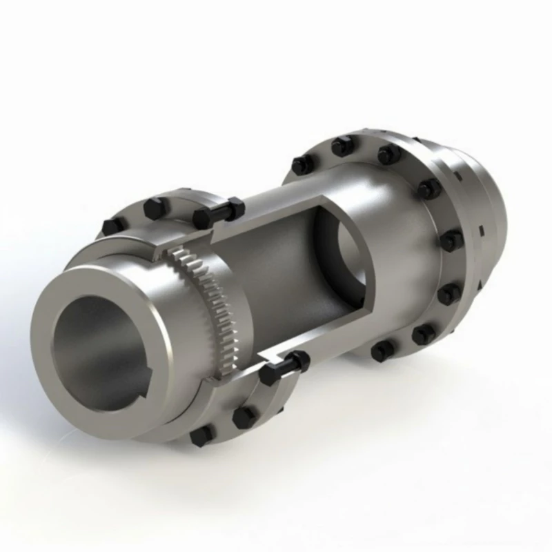
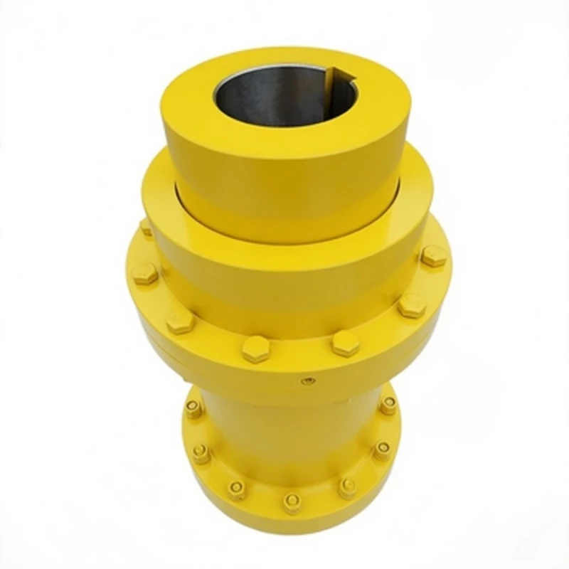
The WGT consists of three components: two crowned-tooth coupling halves mounted on their respective shafts, and an intermediate sleeve spanning the gap between them. The sleeve transmits torque between the two halves through the crowned tooth mesh at each end, and can be removed and replaced without moving either shaft. This three-piece design provides a decrease-out spacer — an invaluable maintenance feature on drives where shaft-end access requires clear space between the motor and the driven machine.
The WGT covers the same 24-size range as the WG base series — from WGT1 (710 N·m) to WGT24 (1,250,000 N·m).
Technical Definition and Working Principle
The Three-Piece Architecture — Hubs, Sleeve, and the Axle Withdrawal Principle
The WGT's defining feature is its three-piece construction. Each coupling half consists of a hub with external crowned teeth that mesh with internal straight teeth in a short outer sleeve section. The intermediate sleeve — the central component that defines the WGT — connects the two outer sleeve sections and spans the shaft gap. Torque is transmitted from shaft to hub, through the crowned tooth mesh at each end of the sleeve, and across the sleeve body to the far coupling half.
Axle withdrawal works as follows: both hubs remain fixed to their respective shafts throughout the maintenance procedure. The outer sleeve sections at each end of the intermediate sleeve are disconnected, and the sleeve is slid axially clear of one or both coupling halves. This exposes the shaft ends, bearing housings, and hub faces without requiring any movement of the motor or driven machine. With the WGT, axle withdrawal takes 20–40 minutes and requires no realignment after the sleeve is refitted.
The high rigidity of the WGT intermediate sleeve is a key performance characteristic. The sleeve is a solid-walled steel tube machined to close tolerances, not a thin-walled or elastomeric component. This means the WGT transmits torque and accommodates misalignment through the gear tooth mesh alone, not through flexure of the spacer body — delivering the full misalignment tolerance and torque capacity of the WG gear mesh.
Crowned Tooth Geometry and Misalignment on Long-Span Drives
Each end of the WGT intermediate sleeve carries a crowned-tooth gear mesh interface — two meshes in total, one per coupling half. Each mesh accommodates angular misalignment of 1.0 to 1.5 degrees, radial offset, and axial displacement independently. The WGT can therefore accommodate misalignment at both shaft ends simultaneously.
The axial displacement capability is particularly important on WGT drives with long sleeves. Thermal expansion of the drivetrain during heat-soak is absorbed by the axial sliding of both crowned tooth meshes within their respective outer sleeves — preventing thrust forces at motor or gearbox bearings.
Critical Speed — The Engineering Constraint of Intermediate Sleeve Drives
The intermediate sleeve of the WGT acts as a rotating beam with a critical speed — the rotational speed at which the sleeve's natural lateral vibration frequency coincides with the rotational frequency. For short sleeves near Hmin, the critical speed is well above operating speed. For longer sleeves, careful engineering analysis is required to ensure operating speed does not approach critical speed.
The WGT catalogue provides the weight and inertia per 10 mm of added sleeve length for each size, enabling engineers to perform critical speed calculations for specific H values. Our engineering team performs this calculation as a standard part of every WGT order when sleeve length and operating speed are provided.
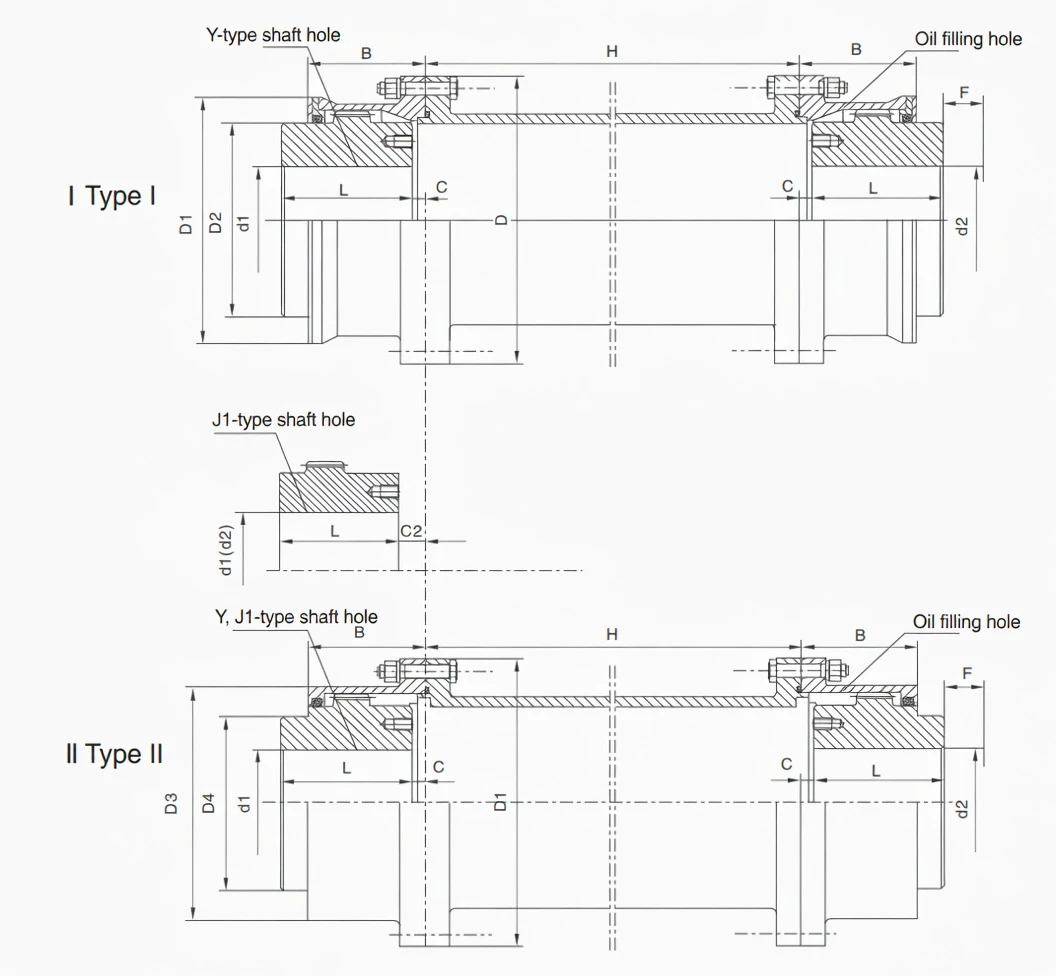
Type I and Type II Construction
For WGT1 through WGT14, both Type I (single outer sleeve) and Type II (with inner bore collar, B1 engagement) are available. Type II is preferred on drives with significant axial thrust or shock loading. For WGT15 through WGT24, only Type I is available.
Comparison with Other Coupling Types for Long-Span Drives
| Feature |
WGT (this product) |
WG (compact) |
Flexible Spacer Coupling |
Jaw Coupling |
| Axle Withdrawal |
Yes — sleeve removes without shaft movement |
No — shaft must move axially |
Yes — spacer drops out |
No |
| Shaft Span Capability |
Customisable H from Hmin upward |
Fixed B dimension only |
Variable length available |
Fixed only |
| Torque Transmission Method |
Crowned gear teeth — rigid |
Crowned gear teeth — rigid |
Disc pack or elastomer — flexible |
Elastomer — flexible |
| Angular Misalignment Tolerance |
1.0–1.5 deg per mesh (2 meshes) |
1.0–1.5 deg per mesh (2 meshes) |
Up to 1 deg (disc); higher (elastomer) |
Up to 1 deg |
| Shock Load Tolerance |
Excellent — crowned teeth |
Excellent |
Poor (disc) / Good (elastomer) |
Good |
| Critical Speed Engineering |
Required for longer H sleeves |
Not applicable |
Required for longer spacers |
Not applicable |
WGT in the WG Family — When Shaft Span and Maintenance Access Drive the Selection
The WGT is one of five variants in the WG coupling family and is unique in featuring an intermediate sleeve. The WGT is the correct choice when shaft spacing or maintenance access requirements cannot be met by any other family member.
| Factor |
WG |
WGP |
WGC |
WGZ |
WGT |
| Standard |
JB/T8854.2 |
JB/T7001 |
JB/T7002-93 |
JB/T7003-93 |
JB/T7004 |
| Intermediate Sleeve |
No |
No |
No |
No |
Yes — customisable H |
| Axle Withdrawal |
No |
No |
No |
No |
Yes |
| Braking Feature |
None |
Flat disc — caliper |
None |
Drum — shoe brake |
None |
| Shaft Orientation |
Horizontal |
Horizontal |
Vertical |
Horizontal |
Horizontal |
| Number of Sizes |
24 |
14 |
14 |
14 |
24 |
| Choose When... |
Standard horizontal close-coupled drive |
Caliper disc brake required |
Vertical shaft drive |
Shoe brake required |
Long shaft span; axle withdrawal needed; distant motor-gearbox layout |
Specifications & Size Matrix — WGT1 to WGT24
All specifications are from the WGT catalogue per JB/T7004. Dimensions in millimetres. H is the minimum sleeve length; any H at or above Hmin can be supplied. Weight, inertia, and lubricant values are per coupling assembly at minimum H, excluding the sleeve. Critical speed must be verified when H significantly exceeds Hmin.
WGT1 – WGT14 Specifications (Type I and Type II)
| Size |
Torque
(N·m) |
Speed
(rpm) |
Bore Range
(mm) |
Y bore |
J1 bore |
D |
D1 |
D2 |
D4 |
B |
Hmin
(mm) |
Weight I
(Kg) |
Weight II
(Kg) |
Lube I
(Kg) |
Lube II
(Kg) |
| WGT1 |
710 |
7500 |
12–42 |
32–112 |
–/44/84 |
122 |
115 |
98 |
60 |
58 |
75 |
5.66 |
4.86 |
0.085 |
0.04 |
| WGT2 |
1250 |
6700 |
22–56 |
52–112 |
–/60/84 |
150 |
145 |
118 |
77 |
68 |
80 |
9.78 |
7.48 |
0.09 |
0.06 |
| WGT3 |
2500 |
6300 |
22–63 |
52–142 |
–/60/107 |
170 |
165 |
140 |
90 |
80 |
80 |
16.7 |
12.2 |
0.17 |
0.10 |
| WGT4 |
4500 |
5600 |
30–80 |
82–172 |
–/84/132 |
200 |
195 |
160 |
112 |
90 |
100 |
25.6 |
19.6 |
0.25 |
0.15 |
| WGT5 |
7100 |
5300 |
30–90 |
82–172 |
–/84/132 |
225 |
215 |
180 |
128 |
100 |
100 |
35.0 |
26.1 |
0.35 |
0.22 |
| WGT6 |
10000 |
5000 |
32–100 |
82–212 |
–/107/167 |
245 |
230 |
200 |
145 |
112 |
100 |
51.6 |
38.0 |
0.40 |
0.29 |
| WGT7 |
14000 |
4500 |
32–110 |
82–212 |
–/107/167 |
272 |
265 |
230 |
160 |
122 |
120 |
68.6 |
45.0 |
0.60 |
0.44 |
| WGT8 |
20000 |
4250 |
55–125 |
112–212 |
–/107/167 |
290 |
272 |
245 |
176 |
136 |
120 |
79.5 |
55.8 |
0.75 |
0.55 |
| WGT9 |
25000 |
4000 |
65–140 |
142–252 |
107/202 |
315 |
305 |
265 |
190 |
140 |
155 |
106.5 |
80.5 |
1.0 |
0.79 |
| WGT10 |
40000 |
3550 |
75–160 |
142–302 |
107/242 |
355 |
340 |
300 |
225 |
165 |
155 |
158.8 |
121.8 |
1.3 |
0.9 |
| WGT11 |
56000 |
3000 |
85–180 |
172–302 |
132/242 |
412 |
385 |
345 |
256 |
180 |
175 |
216.6 |
169.6 |
1.6 |
1.23 |
| WGT12 |
80000 |
2800 |
120–200 |
212–352 |
167/282 |
440 |
435 |
375 |
288 |
207 |
205 |
305.3 |
245.3 |
2.6 |
1.90 |
| WGT13 |
112000 |
2500 |
140–220 |
252–352 |
202/282 |
490 |
480 |
425 |
320 |
235 |
205 |
394.5 |
313.5 |
3.3 |
2.4 |
| WGT14 |
160000 |
2300 |
160–260 |
302–410 |
242/330 |
545 |
540 |
462 |
362 |
265 |
240 |
529.5 |
430.5 |
4.8 |
3.7 |
WGT15 – WGT24 Specifications (Type I Only)
| Size |
Torque (N·m) |
Speed (rpm) |
Bore Range (mm) |
Y bore length |
D |
D2 |
D4 |
B |
Hmin (mm) |
Weight I (Kg) |
Lube I (Kg) |
| WGT15 |
224000 |
2100 |
160–280 |
302–470 |
580 |
488 |
400 |
280 |
240 |
684.5 |
5 |
| WGT16 |
280000 |
1900 |
180–300 |
302–470 |
650 |
560 |
440 |
300 |
240 |
948.2 |
7 |
| WGT17 |
355000 |
1800 |
200–320 |
352–470 |
690 |
600 |
460 |
325 |
280 |
1059 |
8 |
| WGT18 |
450000 |
1700 |
220–360 |
352–550 |
750 |
650 |
510 |
350 |
280 |
1399 |
10 |
| WGT19 |
560000 |
1600 |
240–380 |
410–550 |
775 |
690 |
535 |
372 |
350 |
1544 |
11 |
| WGT20 |
710000 |
1500 |
260–400 |
410–650 |
825 |
730 |
580 |
393 |
350 |
2099 |
13 |
| WGT21 |
800000 |
1300 |
280–440 |
470–650 |
925 |
825 |
620 |
404 |
350 |
2482 |
20 |
| WGT22 |
900000 |
950 |
320–460 |
470–650 |
950 |
850 |
665 |
415 |
400 |
2797 |
26 |
| WGT23 |
1000000 |
900 |
360–500 |
550–650 |
1030 |
900 |
710 |
440 |
400 |
3183 |
29 |
| WGT24 |
1250000 |
850 |
380–520 |
550–800 |
1060 |
925 |
730 |
450 |
400 |
3801 |
32 |
Intermediate Sleeve Incremental Weight and Inertia — Per 10 mm of Added Sleeve Length
Use these values to calculate total system weight and rotational inertia for any sleeve length H above Hmin. Total weight = coupling halves weight + (sleeve additional weight/10mm) × (H - Hmin)/10. Critical speed must be verified separately for the specified H value.
| Size |
Max Speed
(rpm) |
Hmin
(mm) |
Add. Weight I
per 10mm (Kg) |
Add. Weight II
per 10mm (Kg) |
Add. Inertia I
per 10mm (Kg·m²) |
Add. Inertia II
per 10mm (Kg·m²) |
| WGT1 |
7500 |
75 |
0.088 |
0.08 |
0.00011 |
0.000088 |
| WGT2 |
6700 |
80 |
0.13 |
0.125 |
0.00022 |
0.00021 |
| WGT3 |
6300 |
80 |
0.16 |
0.16 |
0.00041 |
0.00038 |
| WGT4 |
5600 |
100 |
0.20 |
0.19 |
0.0008 |
0.00071 |
| WGT5 |
5300 |
100 |
0.23 |
0.22 |
0.0012 |
0.0010 |
| WGT6 |
5000 |
100 |
0.26 |
0.24 |
0.0017 |
0.0013 |
| WGT7 |
4500 |
120 |
0.32 |
0.30 |
0.0030 |
0.0027 |
| WGT8 |
4250 |
120 |
0.32 |
0.30 |
0.0030 |
0.0030 |
| WGT9 |
4000 |
155 |
0.42 |
0.40 |
0.0045 |
0.006 |
| WGT10 |
3500 |
155 |
0.46 |
0.45 |
0.0064 |
0.009 |
Note: For WGT11–WGT24 incremental sleeve data and allowable rotational speed vs H length tables, contact our engineering team or refer to the full catalogue. Critical speed must always be verified when specifying H significantly above Hmin.
Custom Sleeve Length H, Non-Standard Bore, and Critical Speed Analysis Available
Specify any H value at or above Hmin. We machine each sleeve to the exact H required and perform critical speed verification for your operating speed and H combination as a standard part of every WGT order. Send us your motor-to-machine shaft gap, shaft bore data, and operating speed for a same-day engineering assessment.
Technical Advantages — Crowned Tooth on Long-Span Drives
Higher Misalignment Tolerance — Both Shaft Ends, Independent Compensation
The WGT has two independent crowned-tooth meshes — one at each end of the intermediate sleeve. Each mesh independently accommodates 1.0–1.5 degrees of angular misalignment, meaning the WGT can tolerate misalignment at both shaft ends simultaneously. A straight-tooth intermediate shaft coupling transmits all misalignment as bending stress into the intermediate shaft itself, risking fatigue failure at the gear mesh interface.
Longer Service Life Under Shock Loads
In documented industrial applications, WGT-type crowned intermediate shaft couplings consistently outlast straight-tooth equivalents by 3–5× under the same combined shock and misalignment duty.
Reduced Bearing Loads at Both Shaft Ends
The WGT's self-centring crowned teeth minimise transmitted bending moments at both mesh interfaces, protecting both motor drive-end bearings and gearbox input bearings from misalignment-induced cyclic loading. This dual bearing protection is particularly valuable on long-span drives where combined bearing replacement cost can exceed the WGT coupling cost by 5–10×.
Lower Maintenance Frequency — Axle Withdrawal Plus Two Lubrication Ports
The WGT's axle withdrawal capability reduces the maintenance event duration for any work requiring shaft-end access from hours to minutes. Combined with two built-in lubrication ports that allow re-lubrication without disassembly at 6–12 month intervals, the WGT minimises both planned and unplanned maintenance on long-span drives.
Suitable for High-Speed Applications — Up to 7500 RPM (WGT1)
WGT1 is rated to 7500 RPM at minimum sleeve length, enabling direct 2-pole motor connections on 50 Hz supplies. For sizes WGT1 through WGT6 at speeds above 3000 RPM, sleeve length H must be verified against the critical speed table before specifying.
Manufacturing & Quality Assurance
Manufacturing Process
WGT coupling halves are manufactured from the same forged alloy steel blanks as the WG base series. The intermediate sleeve is machined from seamless alloy steel tube, finish-turned to close concentricity tolerances on both inner and outer surfaces. The sleeve end faces are machined to perpendicularity within 0.02 mm to ensure correct engagement with the coupling half outer sleeves during assembly.
The coupling crowned teeth are CNC hobbed to DIN Class 7 accuracy. Tooth flanks are carburised and quenched to HRC 58–62 surface hardness. All bores are finished to H7 tolerance. Z1 taper bores are verified with taper gauges and blue-contact checks for minimum 70% contact.
Quality Control Flow
STEP 1
Material Inspection & Chemistry Check
STEP 2
CNC Hobbing, Sleeve Turning & Bore Machining
STEP 3
Carburising & Quench Hardening
STEP 4
CMM, Sleeve Concentricity, Tooth Profile & Hardness
STEP 5
System Assembly Verification, H Check & Pack
Certifications
ISO 9001:2015 quality management certification covers the full WGT manufacturing process. CE marking applies to applicable sizes. Products manufactured per JB/T7004. Every shipment includes material mill certificates with heat traceability for all three components (both hubs and the sleeve), heat treatment records, and dimensional inspection reports for the assembled system including H dimension verification.
Why Source Your WGT Couplings from RP?
Engineering Support for Sleeve Length and Critical Speed
Specifying a WGT requires more engineering input than a standard compact coupling — the sleeve length H, critical speed verification, and incremental inertia calculations are all application-specific. RP's engineering team performs these calculations as a standard part of every WGT order, providing a confirmed H dimension, critical speed margin, and total system inertia data.
English-Speaking Engineering Team
WGT orders require a technical dialogue — we need your motor-to-machine shaft gap, operating speed, shaft bore diameters, and whether axle withdrawal direction has been determined. Our engineers conduct this dialogue in clear technical English and provide an engineering data sheet for each WGT order.
Sleeve Replacement as a Standalone Spare
The intermediate sleeve is a replaceable component. If a sleeve is damaged, a replacement sleeve can be ordered to the original H dimension without replacing the shaft-mounted hubs — reducing cost and lead time, and eliminating the need for shaft realignment after sleeve replacement. Order a replacement sleeve here.
Full WG Family — One Supplier
As the manufacturer of WG, WGP, WGC, WGZ, and WGT, RP supplies the complete family from a single source. Process plant projects requiring WGT on long-span drives and WG on compact drives are handled through one engineering team, one procurement order, and one documentation package.
Single Units and Project Quantities
WGT couplings and replacement sleeves are available from a single unit. Custom H dimensions add 5–10 working days to standard lead time. Standard sizes at Hmin ship within 15–20 working days ex-works.
Application Case Studies
Case 1: Water Treatment High-Service Pump Drive — Victoria
Customer Profile: A water authority operating 12 high-service pump stations, each with 200–315 kW motors coupled to centrifugal pumps through a 200 mm motor-to-pump shaft gap required for motor ventilation and maintenance access.
Challenge: The authority's previous flexible spacer coupling had experienced three fatigue failures of the spacer tube in 24 months. Root cause analysis identified that critical speed had not been verified against the 1480 RPM operating speed and 220 mm sleeve length combination.
Solution: We supplied 12× WGT7 couplings (14,000 N·m, 90 mm bore, H = 200 mm, Type I) with full critical speed analysis confirming a critical speed of 4,250 RPM at H = 200 mm — a margin of 2.87× above the 1480 RPM operating speed.
Result: 30 months of operation across all 12 stations with zero coupling failures. The authority's engineer documented the critical speed calculation methodology as a new standard for all future spacer coupling specifications. The axle withdrawal capability has been used on four occasions to perform pump mechanical seal replacements, reducing seal replacement outage duration from 5.5 hours to 1.8 hours.
Case 2: Iron Ore Conveyor Motor Withdrawal Drive — Pilbara, WA
Customer Profile: An iron ore producer operating a 47 km overland conveyor with 12 drive stations, each requiring a 350 mm motor withdrawal gap for motor replacement by rail-mounted motor carriage.
Challenge: The original compact WG couplings could not span the 350 mm withdrawal gap required for the motor carriage maintenance system. Temporary shaft blocking was needed for motor changeouts, adding 2–3 hours to each motor replacement event.
Solution: We supplied 12× WGT10 couplings (40,000 N·m, 140 mm bore, H = 350 mm, Type I) with critical speed verified at 2,820 RPM — a 1.98× margin above the 1480 RPM motor speed.
Result: Motor changeout time reduced from 7.2 hours to 3.1 hours. Savings across the 12-drive fleet at 2 motor changeouts per year: approximately 98 hours of recovered drivetrain availability annually.
Case 3: Paper Machine Section Drive — Victoria
Customer Profile: A tissue paper mill operating a tissue machine with 18 section drives (15–90 kW each), where roll bearing replacement averages 4–6 times per year per section.
Challenge: The paper machine's 18 section drives used flexible disc-pack spacer couplings with adequate torque capacity but poor shock load tolerance — occasional web breaks created torsional shock pulses that fatigued the disc packs within 6–8 months. Roll bearing replacement with the disc-pack couplings required 3.5 hours per section.
Solution: We supplied 18× WGT couplings in sizes WGT3 to WGT6 (2,500–10,000 N·m, sleeves from H = 155 to H = 250 mm depending on section) replacing the disc-pack spacers.
Result: Zero coupling failures from web-break torsional shocks across all 18 sections in 28 months since installation. Roll bearing replacement time reduced from 3.5 hours to 55 minutes per section via axle withdrawal — saving approximately 210 hours of machine section downtime per year across the 18-section drive fleet.
Frequently Asked Questions
What is a WGT drum shape gear coupling with intermediate sleeve?
The WGT (JB/T7004) is a crowned-tooth gear coupling with a customisable-length intermediate sleeve that connects two coupling halves across a shaft gap. 24 sizes cover WGT1 (710 N·m) to WGT24 (1,250,000 N·m), up to 7500 RPM. Type I and Type II are available for WGT1–WGT14.
What is the minimum sleeve length H for a WGT coupling?
Minimum H values range from 75 mm (WGT1) to 400 mm (WGT15–WGT24). Any H value at or above Hmin for the chosen WGT size can be supplied. For H values significantly above Hmin, critical speed must be verified — our engineering team performs this calculation for every WGT order as a standard service.
How does axle withdrawal work on a WGT coupling?
Both coupling hubs remain mounted on their respective shafts. To withdraw the sleeve, the fasteners connecting the sleeve to one or both outer hub sleeves are released, and the intermediate sleeve is slid axially clear of one coupling half. After maintenance, the sleeve is refitted and fasteners retorqued — no shaft realignment is required because neither shaft has moved.
What is the critical speed consideration for WGT sleeves?
The intermediate sleeve acts as a rotating beam whose critical speed decreases with increasing H length. For standard short H values near Hmin, the critical speed is well above operating speed. For longer H values, engineering verification is required. We perform this calculation for every WGT order.
How many lubrication points does a WGT coupling have?
Two — one per coupling half. Each half is re-lubricated independently through its own built-in lubrication port. Standard re-lubrication intervals are 6–12 months per half.
Can the intermediate sleeve be replaced independently?
Yes. The sleeve is a separate component that can be ordered and replaced independently of the two coupling hubs. When ordering a replacement sleeve, specify the WGT size and required H dimension. Since the hubs remain on their shafts during sleeve replacement, no realignment is required after fitting the new sleeve.
Specify Your WGT Coupling and Sleeve Length
Send us your motor-to-machine shaft gap (required H), transmission torque, operating speed, shaft bore diameters, and construction type preference (I or II). Our engineering team confirms the right WGT size, verifies critical speed, and provides a factory-direct quotation with full engineering data sheet within 24 hours.
Reply within 24 hours
|
Critical speed analysis included
|
sales@netherlandsdrive.com