SL Type Oldham Coupling — Heavy-Duty Radial Misalignment Compensation for Industrial Drive Systems
Core Product Parameters at a Glance
Nominal Torque 120 – 63,000 N·m
Allowable Speed 70 – 250 r/min
Bore Diameter Range 15 – 200 mm
Max Radial Offset (SL460) 8.0 mm
Angular Tolerance 0.5°
Sizes Available SL70 to SL460 (18 sizes)
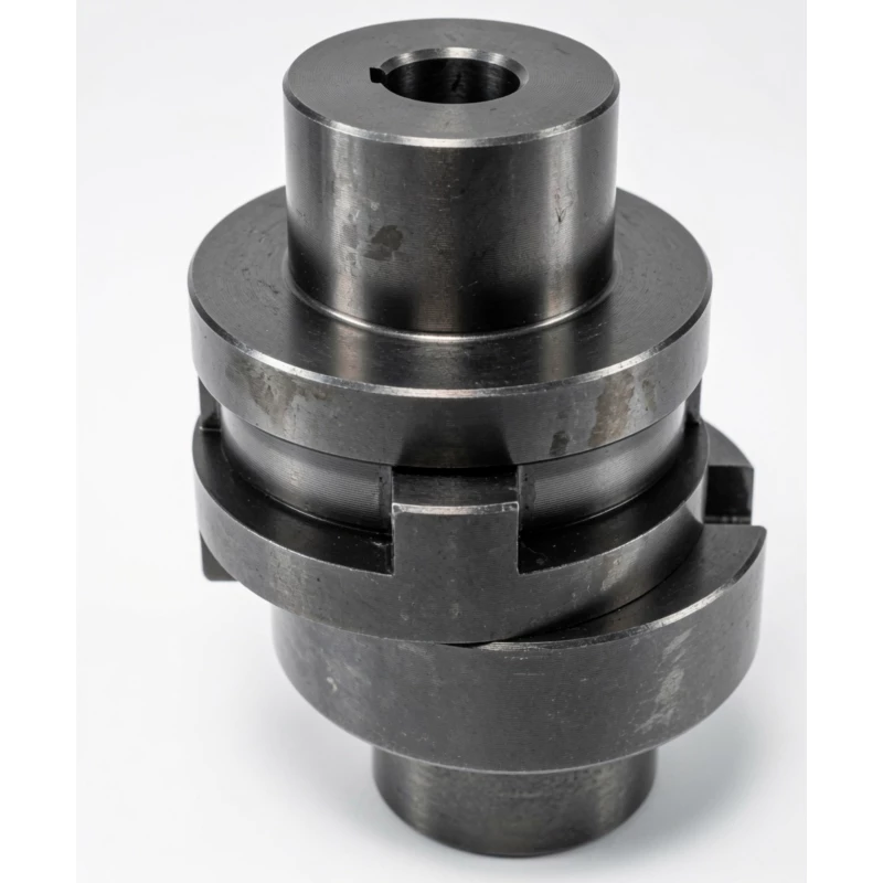
What Is an Oldham Coupling?
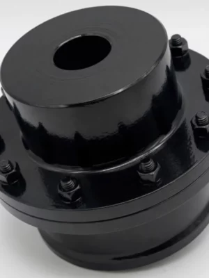
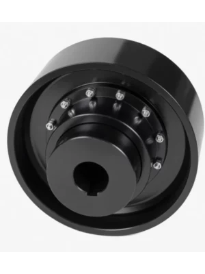
An Oldham coupling is a three-piece mechanical coupling designed to transmit rotary motion between two parallel shafts that are not perfectly aligned. The assembly consists of two metallic hubs — each keyed or clamped to one of the rotating shafts — and a central intermediate disc (also called a slider or middle element) that slides within mating slots machined into each hub face. This sliding cross arrangement allows the centre element to move laterally as the shafts rotate, absorbing radial (parallel) misalignment without generating side-loads on the connected shaft bearings.
The fundamental engineering problem the Oldham design addresses is this: in real machinery, perfect shaft colinearity is rarely achievable. Motor mounting tolerances, thermal expansion, foundation settling, and general assembly variation all introduce some degree of parallel offset between coupled shafts. A rigid coupling transmits these offsets directly to bearings, seals, and shaft spigots, accelerating wear and ultimately causing premature failure. An Oldham coupling intercepts that offset at the floating intermediate disc, keeping the force path clean and the bearing loads predictable.
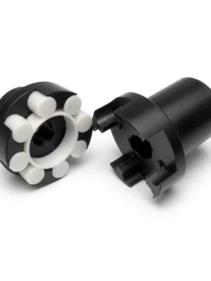
What distinguishes the Oldham design from elastomeric couplings — such as jaw or tyre-type units — is its essentially rigid, zero-backlash torque path. There is no rubber element to fatigue, creep, or change stiffness with temperature. The intermediate disc material (nylon, Delrin/POM, or similar engineering polymer) handles the sliding function without transmitting cyclic bending moments. This makes the Oldham coupling the preferred choice wherever constant velocity ratio, minimal torsional compliance, and long service life under parallel offset are all required simultaneously.
How Does the SL Type Oldham Coupling Work?
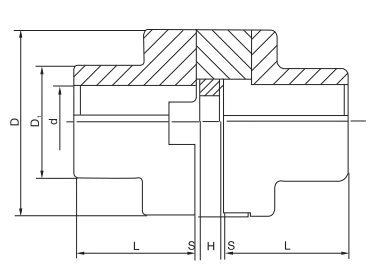
The three-piece structure operates on a straightforward kinematic principle. Each hub face carries a single rectangular tongue, and the intermediate disc carries two perpendicular slots — one on each face — that receive these tongues. As the drive hub rotates, its tongue pushes the disc in one linear direction; the disc simultaneously slides in a perpendicular direction relative to the driven hub. The net result is pure torque transfer with the centre of mass of the disc describing a small circular orbit equal in diameter to the radial offset between the shafts. Critically, the angular velocity ratio between input and output remains exactly 1:1 throughout each revolution — this is the constant-velocity (CV) characteristic that defines the Oldham mechanism.
For the SL series, the allowable radial compensation ranges from 0.6 mm on the SL70 up to 8.0 mm on the SL460. Angular misalignment tolerance is 0.5° across the full range. Axial (end-float) compensation varies from 1.2 mm (SL70) to 7.2 mm (SL460), providing flexibility for thermal shaft growth in long spindle applications. Rated torques span from 120 N·m to 63,000 N·m, and allowable speeds range from 70 r/min (SL460) to 250 r/min (SL70 through SL320).
Because the intermediate disc carries the misalignment kinematically rather than elastically, the torsional stiffness of the coupling is high. There is no energy stored in elastic deformation and no phase lag between input and output torque. This characteristic is particularly significant in servo-driven positioning systems, where any elastic windup would appear as a tracking error. The low rotational inertia of the SL series — as low as 0.002 kg·m² on the SL70 — also minimises the reflected inertia presented to servo drives, enabling faster dynamic response and tighter control bandwidths.
Specifications & Material Options
The tables below list all published performance parameters and dimensional data for the SL series. Use these for initial selection; our engineering team can assist with final confirmation based on your application duty cycle and installation envelope.
SL Type Oldham Coupling — Performance Parameters & Main Dimensions (mm)
| Type |
Nominal Torque Tn (N·m) |
Allowable Speed [n] (r/min) |
Bore Dia. d (mm) |
D (mm) |
D1 (mm) |
L (mm) |
H (mm) |
S (mm) |
Rotational Inertia (kg·m²) |
Weight (kg) |
| SL70 |
120 |
250 |
15–18 |
70 |
32 |
42 |
14 |
0.5 |
0.002 |
1.5 |
| SL90 |
250 |
250 |
20–30 |
90 |
45 |
52 |
14 |
0.008 |
2.6 |
| SL100 |
500 |
250 |
36–40 |
110 |
60 |
70 |
19 |
0.026 |
5.5 |
| SL130 |
800 |
250 |
45–50 |
130 |
80 |
90 |
19 |
0.07 |
10 |
| SL150 |
1250 |
250 |
55–60 |
150 |
95 |
112 |
19 |
0.14 |
15.5 |
| SL170 |
2000 |
250 |
65–70 |
170 |
105 |
125 |
24 |
0.25 |
22.4 |
| SL190 |
3200 |
250 |
75–80 |
190 |
110 |
140 |
29 |
0.5 |
31.5 |
| SL210 |
5000 |
250 |
85–90 |
210 |
130 |
160 |
33 |
0.9 |
45 |
| SL240 |
8000 |
250 |
95–100 |
240 |
140 |
180 |
33 |
1.6 |
59.5 |
| SL260 |
9000 |
250 |
100–110 |
260 |
160 |
190 |
33 |
2 |
76 |
| SL280 |
10000 |
100 |
110–120 |
280 |
170 |
200 |
33 |
3 |
94.3 |
| SL300 |
13000 |
100 |
120–130 |
300 |
180 |
210 |
43 |
1.0 |
4.3 |
111 |
| SL320 |
16000 |
100 |
130–140 |
320 |
190 |
220 |
43 |
5.7 |
129 |
| SL340 |
20000 |
100 |
150 |
340 |
210 |
250 |
48 |
8.4 |
162 |
| SL360 |
32500 |
100 |
160 |
360 |
240 |
280 |
48 |
19.2 |
258 |
| SL400 |
38700 |
80 |
170 |
400 |
260 |
300 |
48 |
26.1 |
305 |
| SL460 |
63000 |
70 |
200 |
460 |
300 |
350 |
58 |
62.9 |
560 |
SL Type Oldham Coupling — Allowable Misalignment Compensation
| Type |
Radial Offset delta y (mm) |
Angular Offset delta a (°) |
Axial Offset delta x (mm) |
| SL70 |
0.6 |
0.5° |
1.2 |
| SL90 |
0.7 |
1.4 |
| SL100 |
1.4 |
1.5 |
| SL130 |
1.8 |
1.8 |
| SL150 |
2.2 |
2.0 |
| SL170 |
2.6 |
2.1 |
| SL190 |
3.0 |
2.2 |
| SL210 |
3.4 |
2.6 |
| SL240 |
3.8 |
3.0 |
| SL260 |
4.0 |
3.4 |
| SL280 |
4.4 |
3.8 |
| SL300 |
4.8 |
4.2 |
| SL320 |
5.2 |
4.6 |
| SL340 |
6.0 |
5.0 |
| SL360 |
6.4 |
5.7 |
| SL400 |
6.6 |
6.4 |
| SL460 |
8.0 |
7.2 |
Material Options
Nylon Intermediate Disc
Lightweight and electrically insulating. Ideal for high-speed lighter-duty applications where cost and mass are priorities. Self-lubricating properties reduce wear between sliding faces.
Delrin / POM Intermediate Disc
Higher rigidity and superior wear resistance compared to nylon. Suitable for heavier torque loads and applications where dimensional stability under load is critical. Low moisture absorption maintains consistent clearance over time.
Aluminium Alloy Hub
The standard choice for most industrial applications. Excellent strength-to-weight ratio, good machinability for custom bores and keyways, and natural resistance to many industrial environments. Anodising or hard-coat options available.
Stainless Steel Hub
Specified for food processing, pharmaceutical, marine, and other corrosive environments. Withstands washdown procedures and aggressive cleaning agents. Grade 304 and 316 options available on request.
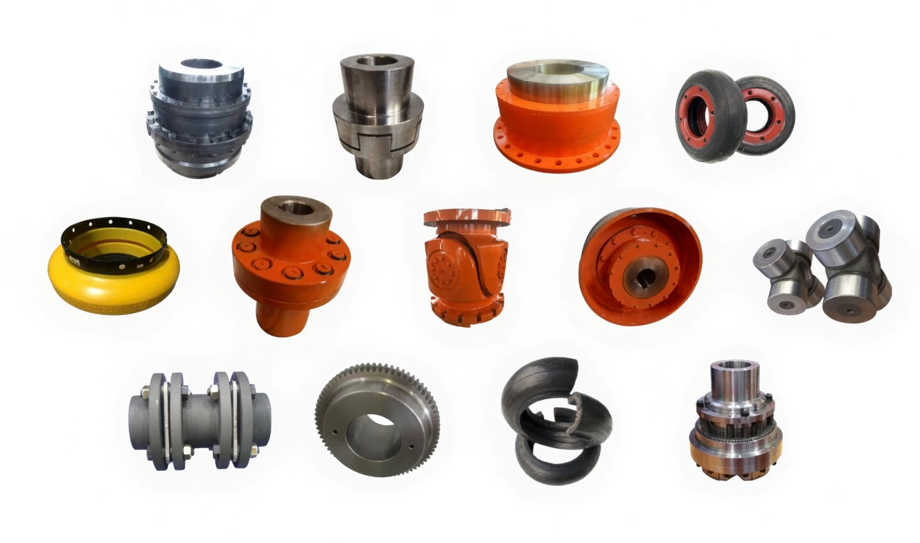
Oldham Coupling vs Other Coupling Types
Selecting the right coupling type starts with matching the compensation requirement and application duty to the coupling's inherent characteristics.
| Parameter |
SL Oldham Coupling |
Jaw Coupling |
Bellows Coupling |
Disc Coupling |
| Parallel Offset Compensation |
Excellent (up to 8 mm) |
Limited (0.1–0.5 mm) |
Low (0.1–0.3 mm) |
Very Low (<0.1 mm) |
| Angular Offset Compensation |
Low (0.5°) |
Moderate (1°–2°) |
Good (1°–3°) |
Low (0.5°–1°) |
| Backlash |
Near Zero |
Low–Moderate |
Near Zero |
Near Zero |
| Electrical Insulation |
Yes (polymer disc) |
Yes (spider) |
No |
No |
| Suitable Speed Range |
70–250 r/min |
Up to 6000 r/min |
Up to 10,000+ r/min |
Up to 10,000+ r/min |
| Installation & Maintenance |
Simple — disc slides out radially |
Simple — spider accessible |
Moderate |
More complex |
| Relative Cost |
Moderate |
Low |
High |
High |
| Constant Velocity Ratio |
Yes — true 1:1 CV |
Yes |
Yes |
Yes |
Why Source Your Oldham Couplings from RP?
Choosing the right supplier is as important as choosing the right coupling. Our quality system, technical depth, and ability to support custom requirements help keep projects on schedule and on budget.
✅
Quality Certifications
Our SL Type Oldham Couplings are manufactured under an ISO 9001 quality management system. Products comply with RoHS directives and are supplied with CE conformity documentation on request. Material test certificates (MTC) for steel and stainless steel hubs are available for critical applications.
⚙
Custom Specification Capability
We support custom bore diameters, keyway profiles (parallel, Woodruff, DIN, and standard), special hub materials, surface treatments (hard anodising, electroless nickel plating, black oxide), and modified intermediate disc materials. Minimum order quantity for custom specifications is 5 pieces, with typical lead times of 7–15 business days from drawing approval.
📞
English-Language Technical Support
🚚
Nationwide Delivery & Returns
Ready to discuss your application? Our team is equipped to assist with selection, sizing, and custom specification. Get in touch with a RP coupling specialist today.
Frequently Asked Questions — SL Type Oldham Coupling
What is the torque range of SL Type Oldham Couplings?
SL Type Oldham Couplings cover a nominal torque range from 120 N·m (SL70) up to 63,000 N·m (SL460), making them suitable for a wide spectrum of industrial drive applications — from light-duty conveyor auxiliaries through to main drives in heavy process equipment.
How much radial misalignment can an SL Type Oldham Coupling compensate?
Depending on the model, SL Type Oldham Couplings can accommodate radial (parallel) misalignment from 0.6 mm on the SL70 up to 8.0 mm on the SL460. Angular displacement tolerance is 0.5° across all sizes. These values should be treated as service limits, not installation targets — minimising residual misalignment always extends service life.
What shaft bore diameters are available?
Standard bore diameters range from 15 mm to 200 mm across the SL70 to SL460 series. Each size offers a bore range — for example, the SL240 accommodates bores from 95 to 100 mm. Custom bore sizes, keyway profiles, and interference fits are available on request with our in-house machining capability.
Can SL Type Oldham Couplings be used in food processing or corrosive environments?
Yes. For food processing and chemically aggressive environments, we recommend specifying stainless steel hubs (Grade 304 or 316) combined with a food-grade nylon or Delrin/POM intermediate disc. These configurations withstand standard CIP washdown procedures and are compatible with international food safety hygiene standards. Contact our team for material certification documentation specific to your audit requirements.
Do you supply SL Type Oldham Couplings to customers globally?
Yes. RP ships globally to industrial customers worldwide. Standard stock items typically dispatch within 2–3 business days with tracked freight. We also work with engineering procurement teams on planned maintenance schedules to pre-position stock for shutdown projects.
What is the difference between an Oldham coupling and a jaw coupling?
The primary difference lies in misalignment compensation mechanism and backlash characteristics. An Oldham coupling uses a rigid intermediate disc with sliding tongue-and-slot interfaces to handle large radial (parallel) misalignment — up to 8 mm in the SL460 — with near-zero backlash. A jaw coupling relies on an elastomeric spider element that deforms to absorb both misalignment and vibration, but introduces more torsional compliance and wears over time. Jaw couplings are better suited for general-purpose drives where vibration damping is needed; Oldham couplings are preferred where precision positioning, high radial offset, or electrical isolation are the primary requirements.
What is the minimum order quantity (MOQ) for custom SL Oldham Couplings?
Standard MOQ for custom specifications — including non-standard bore diameters, keyway configurations, special materials, or surface treatments — is typically 5 pieces. Lead time is generally 7–15 business days from confirmation of final drawings and approval of any required material certifications. Contact us at
sales@netherlandsdrive.com for a confirmed quote and timeline for your specific requirements.
Get a Quote or Technical Datasheet for the SL Type Oldham Coupling
Send us your shaft diameter, torque requirement, and speed, and our engineering team will verify the correct SL size and material specification — usually within one business day.