Audible noise is evidence to investigate, but fault location depends on whether the sound tracks speed, torque or the machine structure.
Helical Gearbox Noise Diagnosis by Speed and Load
read more

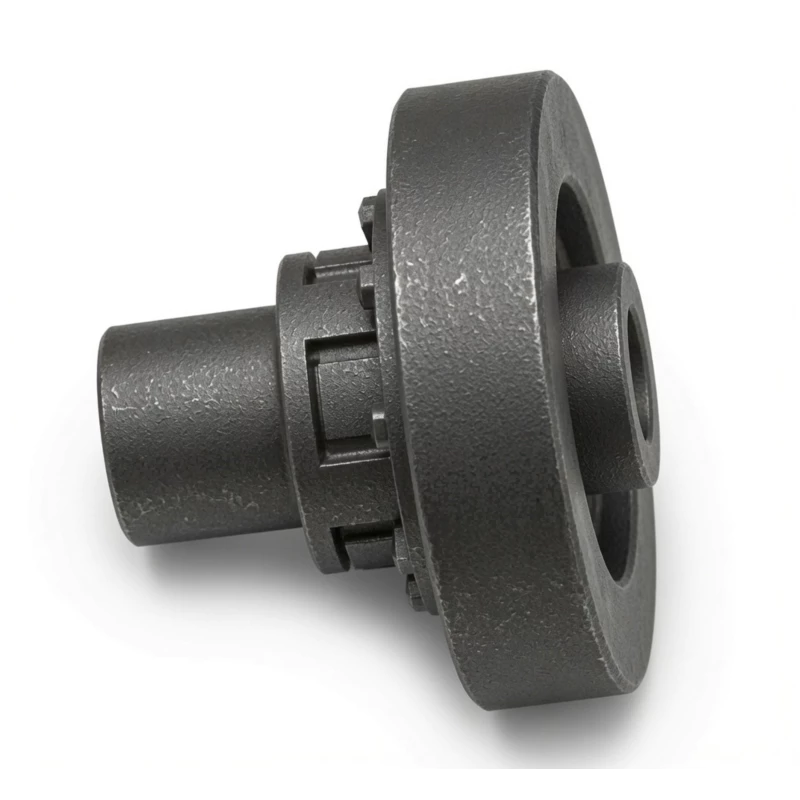
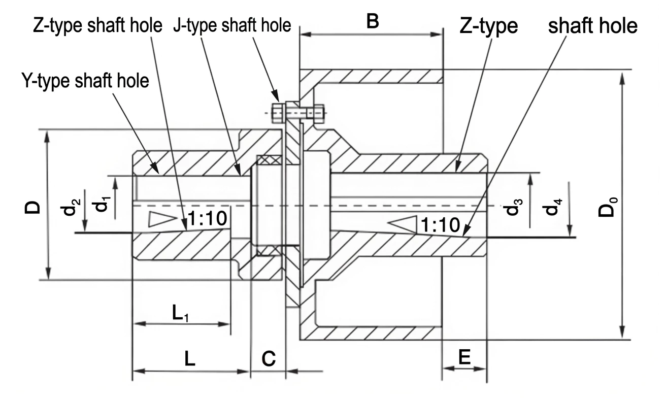
The LMZ-II Type Plum Blossom Coupling with Integral Brake Wheel (GB/T5272-2002) casts the brake drum directly into the coupling hub body, creating the most axially compact brake-coupling unit in the GB/T5272 range. Available in 15 configurations from LMZ5-II-160 to LMZ14-II-800 covering torque up to 12,500 N·m — the preferred choice for space-constrained hoist, crane, and winch drives where the brake drum is replaced infrequently.
MOQ: 50 pcs. Minimum order value USD 1,500; mixed orders and trial quantities welcome.
This page reorganizes the technical information for LMZ-II Type Plum Blossom Coupling with Integral Brake Wheel around the decisions a buyer or engineer normally has to make: duty, shaft interface, alignment, installation envelope, inspection and model selection. All model values are retained in the reference blocks below.
The coupling uses two metal hubs and an elastomeric spider positioned between interlocking jaws. Torque passes through compression of the elastomer, which adds damping and electrical isolation while avoiding the lubrication requirement of all-metal toothed couplings. The spider is also the normal wear element and can be replaced when its condition no longer meets service requirements.
The resilient spider helps absorb shock and torsional vibration between the driving and driven hubs.
The elastomeric transmission element does not require routine grease lubrication.
The jaw-style construction provides a short, practical connection for many motor-to-machine layouts.
Spider condition, hub fit and alignment can be checked during normal maintenance without complex disassembly procedures.
Elastomer hardness and geometry influence torsional compliance, damping, allowable speed and how the coupling reacts to shock. A stiffer insert generally reduces twist while a softer insert can absorb more vibration. The coupling can tolerate limited installation error, but excessive angular, parallel or axial displacement still shortens spider life and can increase loads on connected bearings.
Choose the size from design torque rather than motor power alone. Consider starting peaks, reversing duty, temperature, chemical exposure, bore diameter, hub outside diameter and the available installation envelope. For versions with flanges, brake wheels or brake discs, also verify service access and the brake component dimensions before ordering.
Use the tables below as the dimensional and model reference. Confirm bore, shaft fit, speed, torque and installation envelope before final selection.
| Factor | Choose LMZ-I | Choose LMZ-II |
|---|---|---|
| Brake drum replacement frequency | High (frequent wear) | Low (long service intervals) |
| Axial space available | Sufficient for split ring | Tight — minimum axial length required |
| Drum replacement without shaft movement | Yes (radial removal) | No (hub removal needed) |
| Max torque (standard) | 25,000 N·m | 12,500 N·m |
| Unit cost | Higher (split drum) | Lower |
| Type | Old Type | Nom. Torque N·m | Max Speed rpm | Shaft Bore mm | Bore Length L mm | C mm | E mm | D0 Drum mm | B mm | D mm | |
|---|---|---|---|---|---|---|---|---|---|---|---|
| Y-type | J / Z-type | ||||||||||
| LMZ5-II-160 | MLL4-II-160 | 250 | 4750 | 25,28 | 30–45 | 62 | 38.5 | 20 | 160 | 70 | 105 |
| LMZ5-II-200 | MLL4-II-200 | 250 | 4750 | 25,28 | 30–45 | 62 | 38.5 | 30 | — | 105 | — |
| LMZ6-II-200 | MLL5-II-200 | 400 | 3800 | 30–48 | Same as Y | 82 | 45 | 30 | 200 | 85 | 125 |
| LMZ7-II-200 | MLL6-II-200 | 630 | 3050 | 35*,38* | 40*–56 | 82 | 52 | 30 | — | 145 | — |
| LMZ7-II-250 | MLL6-II-250 | 630 | 3050 | 35*,38* | 40*–56 | 82 | 52 | 40 | 250 | 105 | 145 |
| LMZ8-II-250 | MLL7-II-250 | 1,120 | 2400 | 45*–56 | 60–65 | 112 | 55 | 40 | 250 | 105 | 170 |
| LMZ8-II-315 | MLL7-II-315 | 1,120 | 2400 | 45*–56 | 60–65 | 112 | 55 | 40 | 315 | 135 | 170 |
| LMZ9-II-315 | MLL8-II-315 | 1,800 | 1800 | 50*–56* | 60–80 | 112 | 64 | 40 | 315 | 135 | 200 |
| LMZ9-II-400 | MLL8-II-400 | 1,800 | 1900 | 50*–56 | 60–80 | 142 | 64 | 40 | 400 | 170 | 200 |
| LMZ10-II-400 | MLL9-II-400 | 2,800 | — | 60–75 | 80–100 | 142 | 70 | 39 | 400 | 170 | 230 |
| LMZ10-II-500 | MLL9-II-500 | 2,800 | 1500 | 60–75 | 80–100 | 142 | 70 | 53 | 500 | 210 | 230 |
| LMZ11-II-500 | MLL10-II-500 | 4,500 | 1500 | 70–75 | 80–120 | 142 | 84 | 54 | 500 | 210 | 260 |
| LMZ12-II-630 | MLL11-II-630 | 6,300 | 1200 | 80–95 | 100–130 | 172 | 84 | 59 | 630 | 265 | 300 |
| LMZ13-II-710 | MLL12-II-710 | 11,200 | 1050 | 90,95 | 100–150 | 172 | 98 | 60 | 710 | 300 | 360 |
| LMZ14-II-800 | MLL13-II-800 | 12,500 | 950 | 100–125 | 130–160 | 212 | 98 | 60 | 800 | 340 | 400 |
| Symptom | Likely Cause | Action |
|---|---|---|
| Vibration during running | Worn spider; misalignment | Replace spider; realign shafts |
| Uneven brake grip | Drum runout; worn/glazed shoes | Check runout; reline shoes |
| Spider failure under moderate load | Wrong hardness; service factor too low | Recalculate TC; specify shB if available |
| Drum surface scoring | Lining worn to metal; foreign object | Replace coupling; inspect brake gear |
| Criterion | LMZ-II Integral | LMZ-I Split | LTZ Elastic Pin + Brake |
|---|---|---|---|
| Axial compactness | ★★★★★ Best | ★★★★☆ | ★★★☆☆ |
| Drum replacement | Hub removal needed | In-situ radial | Hub removal needed |
| Drum runout | Lowest (single casting) | Low (half-joint face) | Depends on fit |
| Unit cost | Lowest | Higher | Medium |
| Vibration damping | ★★★★☆ | ★★★★☆ | ★★★☆☆ |
Where a standard or designation is shown below, treat it as a reference tied to the original product data and verify the applicable revision when placing an order.
Set the hub spacing to the value specified for the selected model, align the shafts as closely as practical and verify the spider seats evenly between the jaws. Keys, setscrews or alternative locking features should be matched to the shaft design. Do not force an insert into a gap created by incorrect hub spacing; correct the mechanical position first.
Measure the actual shaft diameters and keyways before machining or confirming a finished bore. A drawing should identify shaft tolerances, key dimensions, required hub position and any shoulder, locknut or axial-retention feature. Alignment readings should be taken after the machine is in its normal installed condition because base distortion, pipe strain, belt pull or thermal growth can move the shaft centers after an initial bench alignment.
After assembly, turn the drive through at least one full revolution by hand where practical. Check for interference with guards, brake hardware and adjacent structures, then verify fastener security. On equipment that changes temperature significantly between start-up and steady operation, compare cold and hot alignment expectations before setting final offsets.
These couplings normally require little routine attention because the elastomer works without grease. Inspection is still important. Look for cracking, permanent set, hardening, softening, heat damage, missing material and polished contact marks that indicate misalignment. Replace the insert before it fails completely so the metal jaws do not make unintended contact.
A coupling should not be used as a permanent correction for poor machine alignment. If vibration, temperature or noise changes after commissioning, compare the current condition with the initial baseline. Check connected bearings and shafts at the same time, because many coupling symptoms originate from looseness, soft foot, imbalance or movement elsewhere in the drivetrain.
For planned maintenance, record the installed model, actual bore sizes, fastener details, lubricant or flexible-element grade where applicable, and the measured alignment at return to service. That information makes later inspection more useful and helps distinguish normal wear from a change in machine condition.
No. Motor power is only a starting point. The selection should use actual torque, service factor, peak load, speed and the driven-machine characteristics.
Confirm the shaft interface first, then the overall installation envelope. Bore, key or locking method, hub length, pilot or flange details and available removal clearance all affect whether a listed model will fit.
Use the model-specific limit as a maximum capability, not as the target installation condition. Better initial alignment usually reduces cyclic load, heat and wear in both the coupling and connected bearings.
Provide a dimensioned shaft drawing or at minimum the shaft diameter and tolerance, keyway, engagement length, shoulder or axial-retention details and required hub position.
Yes. A short follow-up inspection after the machine has run under real load can reveal fastener settlement, lubricant leakage, unexpected movement or alignment change before these develop into a larger problem.
Treat the listed values as the model reference. Select a candidate from torque and speed, then verify every geometric field that affects your installation before issuing the final order drawing.
Used in motor-driven rotating equipment where compact size and vibration damping are useful.
Applicable to start-stop machinery where shock absorption and straightforward maintenance are valued.
Suitable for auxiliary drives where shaft alignment and elastomer condition can be checked during service.
Considered for industrial motion systems when torque, bore size, speed and misalignment remain within the selected model limits.
They are commonly used with pumps, fans, compressors, conveyors, packaging machinery, general manufacturing equipment and other drives that benefit from vibration damping and straightforward maintenance. Brake-equipped variants combine the coupling function with a dedicated braking interface.
The same coupling family can behave very differently in a smooth continuous drive and in a reversing, impact-loaded or frequently started drive. For that reason, application name alone is not enough for selection. Supply the operating torque, peak load, speed, shaft dimensions, expected movement, ambient conditions and required service access so the configuration can be checked against the complete duty.
Audible noise is evidence to investigate, but fault location depends on whether the sound tracks speed, torque or the machine structure.
Flexible couplings accommodate limited relative movement, but poor shaft alignment still affects bearings and seals.
Oil observed on a housing may have traveled from a vent, joint or shaft seal; finding the first wet point is essential.