
Audible noise is evidence to investigate, but fault location depends on whether the sound tracks speed, torque or the machine structure.
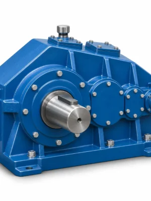
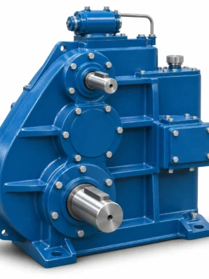
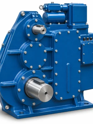
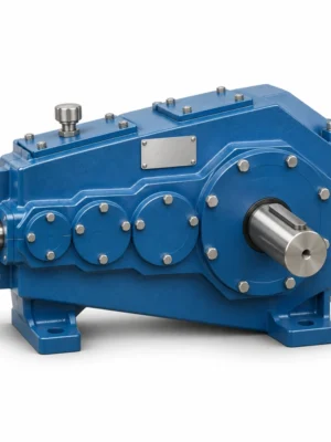
The EP-ZLC Cylindrical Crane Gear Reducer is a crane transmission family organized around three frame-center-distance groups: ZLC600, ZLC750 and ZLC850. The selection process begins with the reducer envelope, the two shaft center distances and the ratio code, rather than assuming that all three frames share an identical speed range. In particular, ZLC750 has its own ratio sequence. An equipment engineer should match the chosen housing to the supporting structure and then check the shaft ends against the existing coupling or driven mechanism.
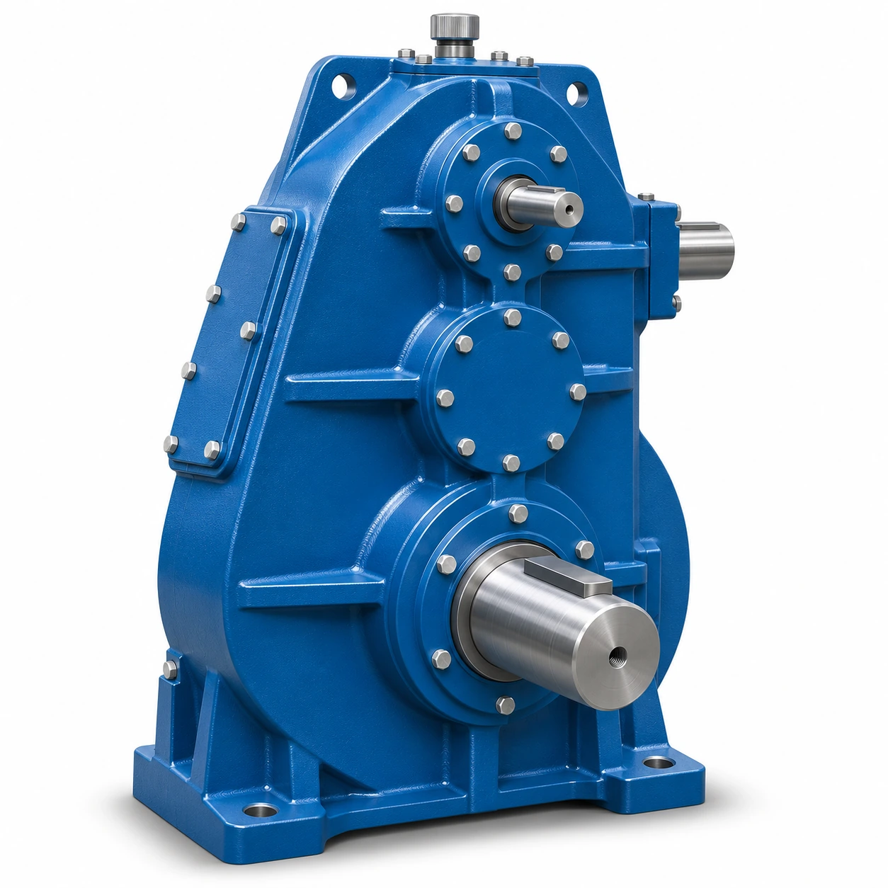
Two-stage gear spacing
The reducer family is organized by a high-speed-stage center distance A1 and low-speed-stage center distance A2.
Frame-dependent installation
A, L, B, H and the foot-hole arrangement vary among the three standard frame groups.
Connection review
Input and output shaft details, keys and bearing design must match the chosen frame.
ZLC Model Identification and Center Distances
The nominal model suffix relates to the overall shaft-center-distance dimension A. A model name does not identify the exact gear-ratio variant, the bearing arrangement, the orientation of an input shaft or the mating coupling. ZLC600 uses a total center distance of 600 mm, assembled from 250 mm and 350 mm stages. The ZLC750 and ZLC850 structures are proportionally larger, with their own geometry. Buyers comparing a retired crane reducer with a proposed replacement should capture all three center distances where practical rather than working from the exterior length alone.
| Frame | Nominal A | High-speed A1 | Low-speed A2 | Center height H0 | Referenced drawing ID |
|---|---|---|---|---|---|
| ZLC600 | 600 | 250 | 350 | 340 | J116G |
| ZLC750 | 750 | 300 | 450 | 320 | J37G |
| ZLC850 | 850 | 350 | 500 | 400 | J165G |
External Envelope and Base-Mounting Dimensions
The arrangement drawing shows the relationship among overall outline, shaft projections and the bolt-hole pattern. The geometry should be checked with the proposed mounting plane established, as the gearbox cannot be positioned reliably from a drawing that has been rotated arbitrarily. Important dimensions include the housing length L, width B, height H, support-face dimensions and bolt-hole pattern. These do not have the same interpretation as gear center distance A.
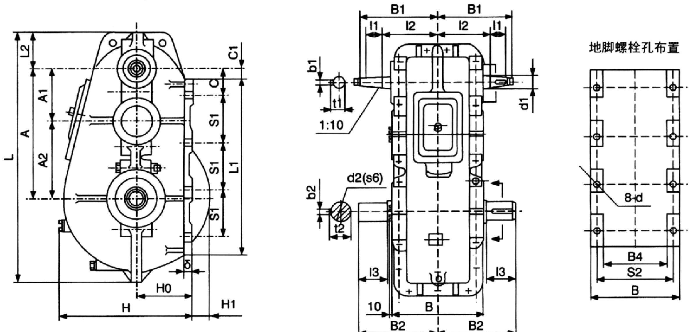
| Frame | L | B | H | B1 | B2 | C | C1 | S1 | S2 | Hole d | Hole n | L1 | L2 | B4 |
|---|---|---|---|---|---|---|---|---|---|---|---|---|---|---|
| ZLC600 | 1190 | 440 | 682 | 400 | 420 | 150 | 80 | 190 | 370 | 25 | 8 | 750 | 180 | 290 |
| ZLC750 | 1448 | 510 | 745 | 450 | 450 | 155 | 55 | 275 | 450 | 25 | 8 | 1020 | 207 | 362 |
| ZLC850 | 1652 | 580 | 915 | 500 | 525 | 155 | 75 | 300 | 520 | 32 | 8 | 1100 | 240 | 430 |
Dimensions shown are reference drawing values. Confirm which face and orientation are used as the installation datum for the supplied gearbox.
When reviewing the mounting pattern, compare the distance between the hole rows with the foundation drawing; check edge distances, plate thickness and the accessibility of the bolt heads. Allow room for lifting tackle and any cover that must be removed during inspection. A gearbox that appears to have adequate exterior clearance in plan view can still be difficult to maintain if the input coupling guard or oil-filling point is obstructed after installation.
ZLC Gear Ratio Codes and Output Speed Planning
Gear ratio selection must be tied to the exact model and operating input speed. A high ratio reduces speed, but the output torque permitted under the crane duty also depends on gear design, loading history and service conditions. For this reason the ratio table is a configuration reference, not a torque rating. Divide the chosen input speed by the candidate ratio to estimate ideal output speed before checking efficiency, slippage elsewhere in the drive and the final driven equipment requirements.
| Frame | 1 | 2 | 3 | 4 | 5 | 6 | 7 | 8 | 9 | 10 | 11 | 12 |
|---|---|---|---|---|---|---|---|---|---|---|---|---|
| ZLC600 / ZLC850 | 49 | 44.69 | 41 | 34.41 | 31.63 | 27.24 | 23.74 | 20.26 | 15 | 12.16 | 10.36 | 8.48 |
| ZLC750 | 48.57 | 40.17 | 31.5 | 23.34 | 20.49 | 15.75 | 12.64 | 10.35 | 8.23 | 7.875 | 4.67 | Not listed |
Code 12 has no corresponding ZLC750 ratio entry in the reference series; do not extrapolate a value.
For instance, a commissioning team might know the measured input speed but not the original reduction code. In that case, the actual driven speed and machine ratio should be measured and reconciled before selecting a replacement. If the previous drive used an additional chain, open gear, belt stage or wheel reduction, the complete machine ratio will differ from the enclosed gearbox ratio. A request for the same drum speed must therefore include the remainder of the drive train.
Assembly Positions and Gearbox Orientation
The ZLC family reference includes a series of assembly-position sketches. These indicate different spatial relationships between the shaft ends and housing rather than different product families. An order that specifies only a center distance and reduction ratio is incomplete if the motor, shaft guard or output coupling occupies a constrained position around the machine. Confirm the chosen orientation by annotating the installation drawing with input, output and the external viewing direction.
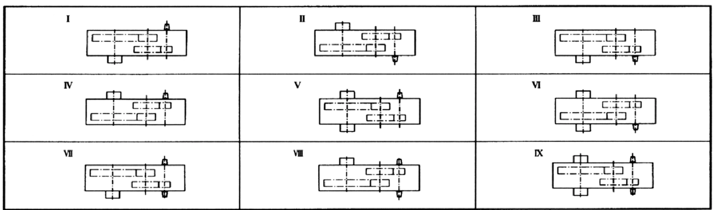
- Reference view: state which end of the gearbox is being observed and which surface rests on the support structure.
- Motor-side connection: identify coupling type, shaft projection and space available for motor removal.
- Driven-side load: identify whether radial force, axial force or a separate bearing support is carried by the gearbox shaft.
- Oil and inspection access: keep plugs, covers and service clearances reachable in the installed orientation.
Shaft Ends, Keys and Bearing Schedule
The shaft-end drawing distinguishes the smaller high-speed shaft from the low-speed output shaft and uses symbols d1, d2, b1, b2, t1, t2 and l3. Shaft keys are not interchangeable simply because the nominal diameters look close. The ZLC750 specification contains alternative values for several low-speed-side dimensions. The ordered variant should state the selected output dimension explicitly; the shaft-end geometry must then be checked against the coupling bore and hub length.
| Frame | H1 | l1 | l2 | l3 | d1 | d2 | b1 | b2 | t1 | t2 | Delta |
|---|---|---|---|---|---|---|---|---|---|---|---|
| ZLC600 | 0 | 110 | 260 | 165 | 60 | 110 | 16 | 28 | 31.4 | 116 | 30 |
| ZLC750 | 105 | 110 | 310 | 165 or 130 | 60 | 110 or 90 | 16 | 28 or 25 | 31.4 | 116 or 95 | 35 |
| ZLC850 | 100 | 135 | 330 | 200 | 90 | 140 | 24 | 36 | 49 | 147.2 | 40 |
The ZLC750 low-speed shaft value d2 and related dimensions are variant-dependent; quote the chosen option and request a confirmation drawing.
| Frame | Driving shaft bearings | Intermediate bearings | Driven shaft bearings | Reference mass (kg) |
|---|---|---|---|---|
| ZLC600 | 412 x 2 | 7318 x 2 | 7318 x 1 | 728 |
| ZLC750 | 412 x 2 | 7318 x 2 | 7526 x 1 | 1022 |
| ZLC850 | 7318 x 2 | 7324 x 2 | 7526 x 1 and 7530 x 1 | 1640 |
Bearing identifiers and mass entries describe the referenced configuration. Confirm actual bearing schedule and shipping mass with the current drawing or order confirmation.
Choosing a ZLC Reducer for a Crane Mechanism
An engineer selecting ZLC for a travel or hoisting mechanism should establish the duty boundary before interpreting the size table. If the gearbox is on a hoist, braking and suspended-load control need attention from the system designer; the gearbox should not be represented as a holding or safety brake. If it is on a travel drive, frequent reversals,wheel load and the point where the output shaft is supported can dominate shaft loading. The reduction ratio sets the broad speed relationship, but it cannot substitute for a verified output torque and service duty.
Speed and ratio
Document input revolutions per minute, required output speed and every external transmission stage.
Peak and repeated duty
Distinguish occasional acceleration or reversal events from running load before requesting a torque assessment.
Foundation and alignment
Compare the bolt footprint and shaft center lines, with clearances for coupling guards and inspections.
For a wider crane-reducer comparison, the QJR medium-hardened crane reducer and QJS higher-reduction gearbox provide different product-family starting points. Their frame dimensions and mechanical interfaces are not assumed interchangeable with ZLC. A practical project review compares available design approaches against the same application and drawing set rather than selecting on a similar product photograph.
Retrofit Measurement and Integration Checklist
For a retrofit, record the position of the main bearing support, any intermediate shaft, output coupling and foundation fixing holes. Establish a single datum system for the replacement drawing, especially if the original reducer is still mounted in a crane framework. Where the replacement is moved by a few millimeters, evaluate the effect on shaft coupling alignment, adjacent guards and the position of oil or inspection openings. Modification to the steelwork should not be assumed acceptable without engineering approval.
- Measure the existing housing length, width, height and the input-to-output shaft centerline relationship.
- Record both shaft-end diameters, projections, keyways, coupling hubs and the direction of the driven load.
- Provide the existing motor rated speed and actual output speed; identify any reduction stage outside the gearbox.
- Send a dimensioned foundation or mounting drawing with the required orientation marked.
- Confirm the permitted operating torque, bearing reactions, lubrication method and any inspection documentation needed for handover.
Ordering and Documentation for ZLC Series
For quotation preparation, specify ZLC600, ZLC750 or ZLC850 together with the requested ratio code, shaft-end option, installation position and quantity. If the requirement concerns an old machine, send the nameplate and installation drawing even when the model reference is legible. The engineering review can then separate items determined by the reference series from items dependent on the selected construction, including the ZLC750 output dimension. Inspection and production documents should identify the agreed drawing revision and the key fit dimensions rather than being inferred from general product photographs.
Frequently Asked Questions
The following answers focus on the decisions that typically need to be resolved before an engineer can confirm a suitable crane gearbox configuration.
Find the Appropriate ZLC Gear Reducer
Send your frame reference, ratio, shaft-end requirements, mounting drawing and quantity. Ever Power can discuss a configuration-focused quotation without assuming that all sizes share the same dimensions or duty limits.