
Audible noise is evidence to investigate, but fault location depends on whether the sound tracks speed, torque or the machine structure.
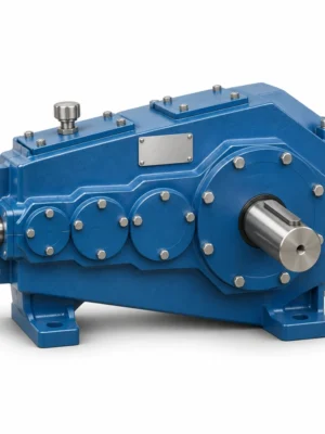
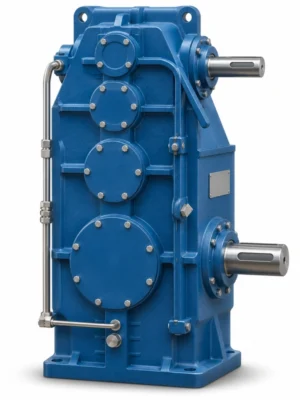
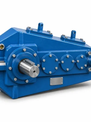
EP-QJYD3 Foot-Mounted Three-Stage Hardened Crane Gearbox is specified for combined three-stage ratio and rigid foundation interface. A QJYD3 foot-mounted crane gearbox is specified by the relationship between the reducer base and its driven equipment. It adds a foundation-dependent interface to the three-stage gear train, which makes base dimensions, elevation and clearance essential quotation information. The foundation cannot be assumed to match a QJY3 basic arrangement or another foot-mounted stage family. A practical replacement evaluation must consider where the motor, reducer and output coupling are actually situated in the crane structure.
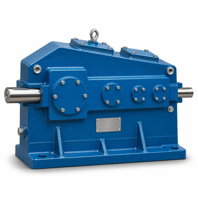
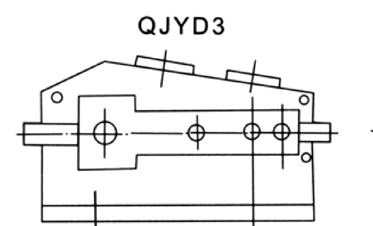
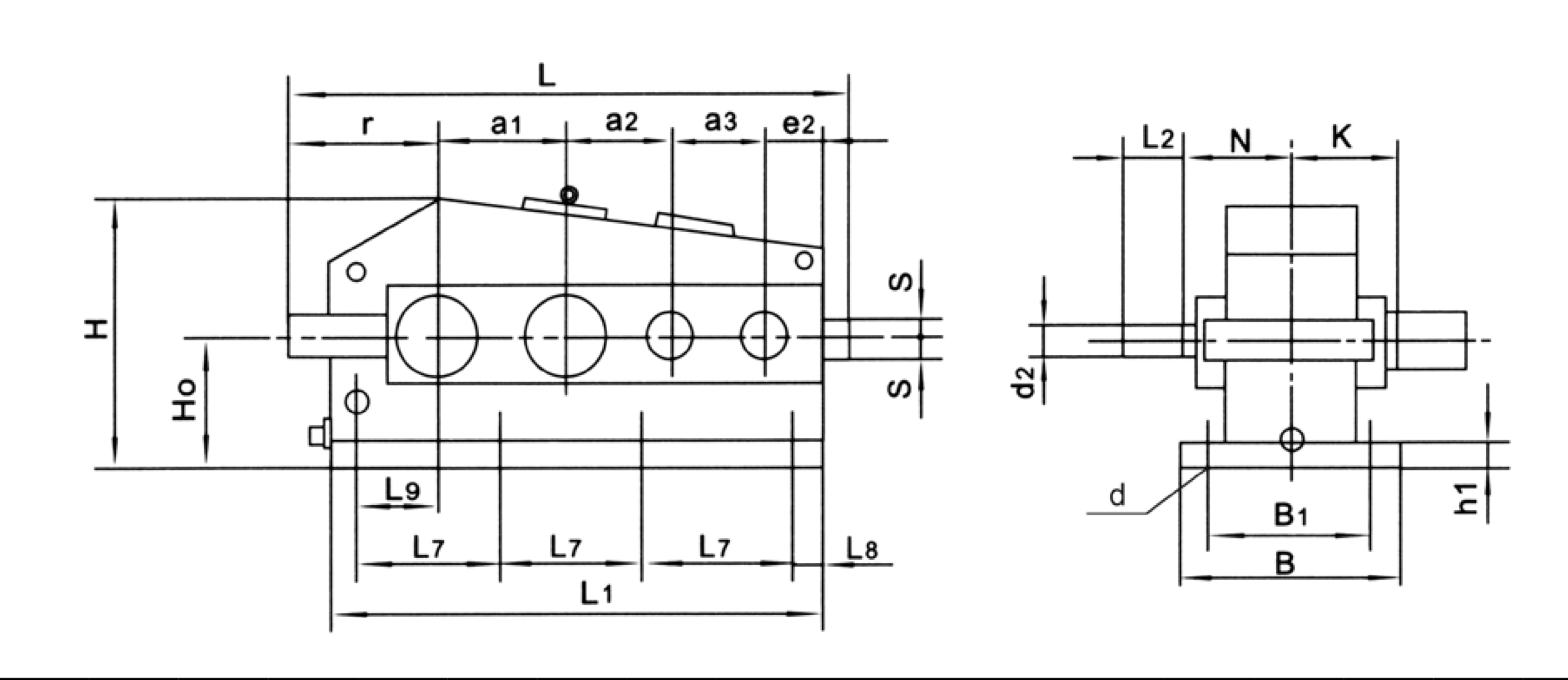
The QJYD3 dimension schedule is not the same as the QJYD2 two-stage schedule or the compact configurations. The dimension view selected for publication has to show the exact mounting construction. This matters during planned maintenance because an apparently minor length change can prevent the coupling half from being withdrawn or force modification of a guard. When considering a series-level 20–100 nominal ratio, the selected centre distance and duty rating need to be determined together.
QJYD3 specification and model identification
QJYD3 Foot Mounted Crane Gearbox selection is defined by the combination of family construction, operating point and machine interfaces. The following data identifies the documented product family; a specific configuration must still be checked against its dimensional drawing and duty schedule.
| Parameter | Series-level reference |
|---|---|
| Drive layout | Three-stage, foot-mounted QJYD3 |
| Nominal ratio | 20–100 in associated three-stage family |
| Nominal centre-distance range | 170–800 mm family |
| Source-specific dimensional sheet | QJYD3 foot-mounted dimension set, separate from QJYD2/QJYD23 |
| Main selection factors | Base pattern, shaft centre heights, torque and duty |
The nominal centre-distance schedule below covers 13 named frame entries. It is a series index, not a statement that every combination of nominal ratio, shaft end and mounting exists at every size.
| Frame reference | Nominal centre distance | Ordering condition |
|---|---|---|
| Nominal centre a1 = 170 mm | 170 mm | Confirm ratio, interface and load rating for the requested version |
| Nominal centre a1 = 200 mm | 200 mm | Confirm ratio, interface and load rating for the requested version |
| Nominal centre a1 = 236 mm | 236 mm | Confirm ratio, interface and load rating for the requested version |
| Nominal centre a1 = 280 mm | 280 mm | Confirm ratio, interface and load rating for the requested version |
| Nominal centre a1 = 335 mm | 335 mm | Confirm ratio, interface and load rating for the requested version |
| Nominal centre a1 = 370 mm | 370 mm | Confirm ratio, interface and load rating for the requested version |
| Nominal centre a1 = 400 mm | 400 mm | Confirm ratio, interface and load rating for the requested version |
| Nominal centre a1 = 450 mm | 450 mm | Confirm ratio, interface and load rating for the requested version |
| Nominal centre a1 = 500 mm | 500 mm | Confirm ratio, interface and load rating for the requested version |
| Nominal centre a1 = 560 mm | 560 mm | Confirm ratio, interface and load rating for the requested version |
| Nominal centre a1 = 630 mm | 630 mm | Confirm ratio, interface and load rating for the requested version |
| Nominal centre a1 = 710 mm | 710 mm | Confirm ratio, interface and load rating for the requested version |
| Nominal centre a1 = 800 mm | 800 mm | Confirm ratio, interface and load rating for the requested version |
QJYD3 construction, duty and interfacing
Three-stage reduction
A larger nominal ratio means the output runs slower for the same input speed. Establish the required drum or travel motion before selecting from the 20–100 range, and use the actual ratio when the machine has synchronized drives. Do not use a generic catalogue maximum torque as the rating at every speed.
Foot pattern verification
Measure all attachment holes, not only the distance between the first and last hole. Confirm the hole count, the direction of slots if present, base height and relationship to the gear input and output axes. Ask whether the support plate includes keys or stops that transfer horizontal load. When the crane frame has been repaired, compare the actual hole positions with the original machine drawing.
Base stiffness and alignment
A floor-mounted housing can be distorted when bolts draw its feet onto a warped base. Such distortion can lead to gear contact changes and bearing misalignment. Check flatness and shimming, then use appropriate alignment methods on the motor and driven equipment. The drawing should establish the datum for each shaft centreline.
Installation sequence
Inspect shaft end cleanliness, protect the seal lips, lift by designated handling points and position the reducer without forcing bolts. Tighten in the approved sequence, verify coupling alignment, set lubricant for the actual orientation and record the commissioning checks. A carefully staged startup can reveal fit or lubrication problems before full production load.
Motor, brake and coupling
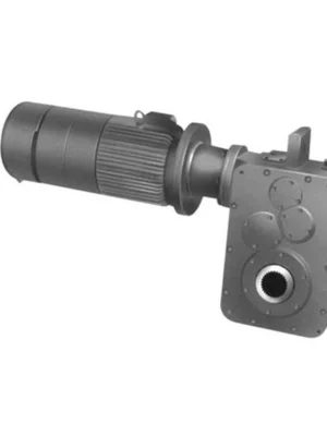
Confirm which parts are supplied with the reducer and which are installed by the machine builder. The motor nameplate and braking scheme affect selection but should not be confused with the gearbox rating. Record coupling engagement, brake installation side and the available service envelope.
Loading under crane duty
Foot mounting is not an alternative to torque and fatigue review. Report static and dynamic output torque, expected starts per hour, reversal frequency, shock events and operating hours. The support structure also needs to withstand the torque reaction that passes through the gearbox feet.
Refurbishment procurement
For an existing plant, provide a foundation plan, two perpendicular shaft views and the distance to adjoining guards. For a newly designed crane, include the complete machine installation layout. This allows the gearbox design review to distinguish permitted dimensional changes from no-change interfaces.
Planning a replacement around the real foundation
For an EP-QJYD3 installation, the main decision concerns combined three-stage ratio and rigid foundation interface. Foot pattern compatibility and operating torque should be considered in the same engineering assessment. The best starting point is the actual machine arrangement, the operating load and the requested output speed.
Select
Confirm the true mechanical work point for QJYD3 Foot Mounted Crane Gearbox: input speed, demanded output torque and the dynamic events that govern component loading.
Measure
Use the QJYD3 dimensional drawing to validate the installation envelope, shaft interfaces, mounting features and clearances on the actual machine.
Integrate
Match the selected drive with the connected motor, brake, coupling and supporting crane structure. Treat fit and control as one application.
Maintain
Plan access for lubrication, seals, inspection and removal. A compatible gearbox should also be practical to service after the crane is installed.
Updating a crane drive without rebuilding the base
Compare the QJYD3 foot plan with the existing machine foundation. Verify centre heights and coupling guard space before choosing the gear ratio and checking mechanical load. The mounting plate and gear rating are separate acceptance tests.
Applications on bolted crane structures
- Overhead crane hoist drive on a shared machine bed: describe the working load and mechanical interface before defining the reducer or gearmotor variant.
- Wheel travel drives with rigid pedestal mounting: describe the working load and mechanical interface before defining the reducer or gearmotor variant.
- Rebuild programs requiring existing bolt locations to remain usable: describe the working load and mechanical interface before defining the reducer or gearmotor variant.
QJYD3 foundation specification checklist
- Mounting feet and bolt-hole coordinates: include the appropriate drawing, measured value, operating cycle or connection detail.
- Structural base flatness/datum: include the appropriate drawing, measured value, operating cycle or connection detail.
- Drive shaft heights: include the appropriate drawing, measured value, operating cycle or connection detail.
- Three-stage nominal ratio: include the appropriate drawing, measured value, operating cycle or connection detail.
- Output torque over load cycle: include the appropriate drawing, measured value, operating cycle or connection detail.
- Available coupling withdrawal space: include the appropriate drawing, measured value, operating cycle or connection detail.
- Inverter/soft starter details: include the appropriate drawing, measured value, operating cycle or connection detail.
- Installation drawing or existing reducer tag: include the appropriate drawing, measured value, operating cycle or connection detail.
Commercial enquiry for the QJYD3 series
Ever Power can discuss model identification, interface drawings and practical order quantities for the QJYD3 Foot Mounted Crane Gearbox. Confirmed product configuration, lead time and delivery terms belong in the quotation. Trial and mixed-model requests can be assessed against the total order value.
To compare related drive families, explore the industrial drive product range. The company overview explains the supplier context for engineering and procurement enquiries.
Frequently asked questions about EP-QJYD3
How is QJYD3 different from QJYD2?
QJYD3 belongs to a three-stage arrangement and its dimensional drawing is distinct from the QJYD2 two-stage foot-mounted family. The correct drawing must be selected from the actual code on the order.
Can the installation holes be repositioned during manufacture?
A revised mounting arrangement may be discussed as an engineered configuration, but the support load path, bearing alignment and surrounding clearances must be reviewed. Supply a marked-up base drawing and do not assume the standard frame is freely interchangeable.
What must be measured before ordering a replacement?
Capture centre height, all foot holes, shaft diameters, coupling positions, gearbox envelope and the surrounding guards. Include motor data and the rated operating torque to support mechanical selection.
Can a first-order crane reducer be ordered in only one or two pieces for EP-QJYD3?
Small orders of 1–2 pieces may be considered at a higher unit price. A new buyer can ask about 1–5 sample units where the engineering and production arrangement is suitable. MOQ is flexible by configuration; mixed-model orders are welcome when the total order value is approximately USD 1,500 or more. For this product, quote preparation should also address combined three-stage ratio and rigid foundation interface and the requested quantity.
What lead time and shipping terms apply after the drawing is approved for EP-QJYD3?
For initial planning, use 10–25 working days for standard configurations, 20–45 for custom components and 45–120 for project units. The binding schedule follows engineering review and order acceptance. EXW/FOB/CIF/DAP are common quotation bases; FCA/CFR/CPT/CIP/DDP can be negotiated on a case-by-case basis. Schedule confirmation follows review of the QJYD3 interface and duty requirements.
Coordinate the QJYD3 foundation interfaces
Send the base drawing, duty conditions and required output speed for an EP-QJYD3 enquiry. We can evaluate the appropriate mounting and shaft arrangement before confirming the configuration.