
Audible noise is evidence to investigate, but fault location depends on whether the sound tracks speed, torque or the machine structure.
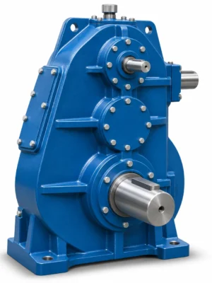
EP-QJ-L Vertical Crane Gear Reducer is specified for vertical shaft arrangement, centerlines and installation height. A QJ-L vertical crane reducer is more than a horizontal gearbox stood on end. Its model range has a dedicated dimensional layout, with three gear centre distances, input-shaft details, output-shaft details, mounting information and unit mass identified for the selected frame. The buying decision therefore begins with the shaft orientation and the relationship between the gearbox datum surfaces and the driven equipment. An existing machine may have insufficient space to accommodate a different output extension or top bearing arrangement.
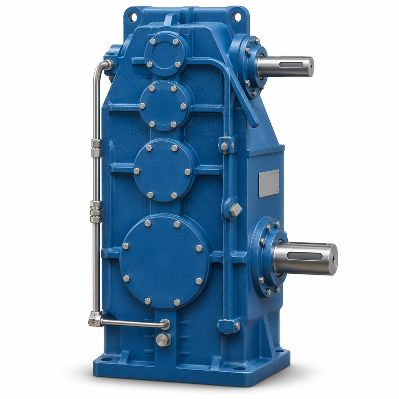
Seven principal QJ-L nominal sizes are identified: 140, 170, 200, 236, 280, 335 and 400. These numbers help identify the relevant dimensional row, but they should not be treated as complete order codes. The nominal ratio, actual ratio, shaft-end detail, rotation direction and application duty remain necessary. A replacement must be assessed at the entire mechanical envelope, especially where a crane mechanism is mounted close to a wall, frame beam or guarding.
QJ-L specification and model identification
QJ-L Vertical Crane Gear Reducer selection is defined by the combination of family construction, operating point and machine interfaces. The following data identifies the documented product family; a specific configuration must still be checked against its dimensional drawing and duty schedule.
| Parameter | Series-level reference |
|---|---|
| Series frames | QJ-L140, 170, 200, 236, 280, 335 and 400 |
| Nominal reduction schedule | 16–100 in the associated series |
| Output | Project-specific solid output shaft and coupled machine interface |
| Dimensional reference | Separate layout and installation tables for the L family |
| Operating assessment | Crane load class, shaft forces, start/reverse duty |
Input/output and housing dimensions
| Model | a1 | a2 | a3 | a03 | d | l1 | N | b1 | t1 | D | l2 | K | b2 | t2 | H | B | L | L0 | N0 | N2 |
|---|---|---|---|---|---|---|---|---|---|---|---|---|---|---|---|---|---|---|---|---|
| QJ-L140 | 140 | 100 | 71 | 311 | 20 | 50 | 120 | 6 | 22.5 | 48 | 82 | 130 | 14 | 51.5 | 300 | 190 | 558 | 167 | 103 | 107 |
| QJ-L170 | 170 | 118 | 85 | 373 | 25 | 50 | 135 | 8 | 28 | 55 | 82 | 150 | 16 | 59 | 355 | 215 | 650 | 192 | 115 | 120 |
| QJ-L200 | 200 | 140 | 100 | 440 | 28 | 60 | 180 | 8 | 31 | 65 | 105 | 175 | 18 | 69 | 405 | 250 | 747 | 217 | 133 | 137 |
| QJ-L236 | 236 | 170 | 118 | 524 | 35 | 80 | 210 | 10 | 38 | 80 | 130 | 200 | 22 | 85 | 475 | 300 | 894 | 260 | 158 | 164 |
| QJ-L280 | 280 | 200 | 140 | 620 | 40 | 110 | 235 | 12 | 43 | 90 | 130 | 220 | 25 | 95 | 557 | 340 | 1035 | 295 | 277 | 211 |
| QJ-L335 | 335 | 236 | 170 | 741 | 45 | 110 | 255 | 14 | 48.5 | 110 | 165 | 260 | 28 | 116 | 654 | 400 | 1243 | 357 | 307 | 241 |
| QJ-L400 | 400 | 280 | 200 | 880 | 55 | 110 | 285 | 16 | 59 | 130 | 200 | 310 | 32 | 137 | 778 | 490 | 1443 | 412 | 352 | 286 |
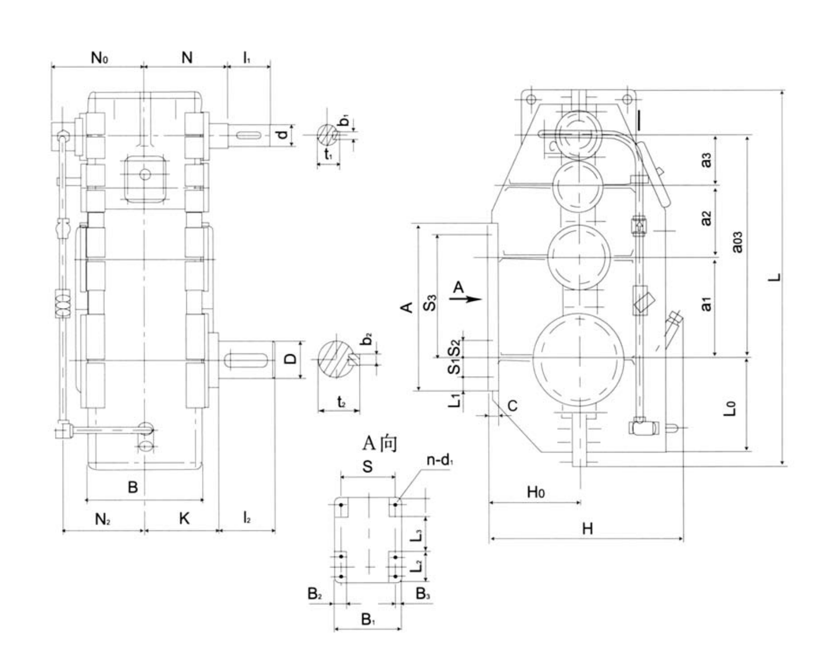
Foundation and mounting dimensions
| Model | H0 | A | S | S1 | S2 | S3 | B1 | B2 | B3 | L1 | L2 | L3 | C | d1 | Holes | Mass kg |
|---|---|---|---|---|---|---|---|---|---|---|---|---|---|---|---|---|
| QJ-L140 | 138 | 260 | 185 | 30 | 0 | 170 | 245 | 60 | 30 | 30 | 80 | 80 | 20 | 21 | 4 | 77 |
| QJ-L170 | 168 | 290 | 205 | 35 | 0 | 205 | 265 | 60 | 30 | 25 | 110 | 110 | 25 | 21 | 4 | 112 |
| QJ-L200 | 193 | 340 | 235 | 40 | 0 | 240 | 295 | 60 | 30 | 30 | 120 | 120 | 25 | 21 | 4 | 165 |
| QJ-L236 | 230 | 405 | 270 | 55 | 55 | 290 | 330 | 60 | 30 | 30 | 180 | 120 | 30 | 21 | 6 | 249 |
| QJ-L280 | 265 | 480 | 320 | 60 | 60 | 340 | 400 | 80 | 40 | 40 | 195 | 120 | 30 | 25 | 6 | 364 |
| QJ-L335 | 315 | 550 | 365 | 60 | 60 | 410 | 445 | 80 | 40 | 40 | 200 | 120 | 35 | 25 | 6 | 647 |
| QJ-L400 | 380 | 680 | 430 | 70 | 70 | 510 | 520 | 90 | 45 | 50 | 240 | 140 | 40 | 31 | 6 | 1048 |
Actual transmission ratios by listed frame
| Model / nominal ratio | 16 | 18 | 20 | 22.4 | 25 | 28 | 31.5 | 35.5 | 40 | 45 | 50 | 56 | 63 | 71 | 80 | 90 | 100 |
|---|---|---|---|---|---|---|---|---|---|---|---|---|---|---|---|---|---|
| QJ-L140 | 15.57 | 17.92 | 19.96 | 23.13 | 24.46 | 28.59 | 32.15 | 35.83 | 40.30 | 45.72 | 49.26 | 55.20 | 63.09 | 68.25 | 78.00 | 90.88 | 103.87 |
| QJ-L170 | 15.82 | 17.86 | 19.95 | 22.64 | 25.44 | 27.78 | 31.45 | 35.22 | 39.87 | 43.34 | 49.21 | 56.39 | 64.04 | 72.06 | 81.82 | 89.29 | 101.39 |
| QJ-L200 | 15.78 | 18.10 | 20.22 | 22.23 | 24.98 | 27.57 | 31.21 | 35.99 | 40.75 | 44.03 | 49.95 | 55.73 | 63.22 | 68.12 | 77.28 | 86.10 | 97.67 |
| QJ-L236 | 15.68 | 18.07 | 20.21 | 22.28 | 25.09 | 27.77 | 31.53 | 34.37 | 41.13 | 43.95 | 50.21 | 53.36 | 64.92 | 71.00 | 81.11 | 85.83 | 98.05 |
| QJ-L280 | 16.51 | 18.19 | 20.26 | 22.39 | 23.69 | 27.72 | 31.18 | 34.83 | 39.15 | 44.41 | 50.76 | 53.69 | 61.36 | 71.84 | 82.11 | 90.04 | 102.91 |
| QJ-L335 | 15.70 | 17.98 | 20.20 | 22.18 | 25.11 | 27.64 | 31.58 | 35.76 | 40.00 | 45.70 | 48.76 | 58.43 | 62.35 | 72.82 | 83.19 | 93.75 | 100.04 |
| QJ-L400 | 15.78 | 18.10 | 20.22 | 22.23 | 24.98 | 27.57 | 31.21 | 36.00 | 40.75 | 44.03 | 49.95 | 55.73 | 63.22 | 68.12 | 77.28 | 86.10 | 97.67 |
QJ-L construction, duty and interfacing
Vertical output design
Confirm whether the shaft must point upward or downward in the actual application and where external loads enter the shaft. A vertical axis changes the way thrust loads are carried, and gravity can affect seals and lubrication. The unit needs a matching permitted installation orientation, not an assumption based solely on the housing sketch.
Actual versus nominal ratio
The QJ-L schedule provides actual ratios for common nominal reductions. If a crane travels on matched drive units, compare actual ratios rather than using rounded nominal values. A mismatch may produce uneven loads or tracking issues when wheels are driven at different speeds by nominally similar gearboxes.
Mounting and foundation
Use the model-specific installation table for mounting hole size and count. Check base or bracket flatness and the available service access. If the unit is attached to a tall crane structure, consider structural deflection under loaded operation as well as alignment during installation.
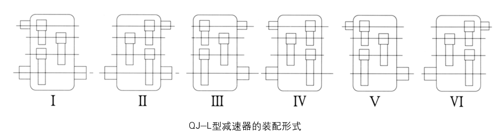
Complete size table
The QJ-L frame list includes low-, middle- and high-speed stage centre distances plus a total centre-distance figure. Those values are useful when assessing space and recognizing the correct unit from an older equipment drawing. Different overall heights and lengths need to be checked for clearance.
Output bearing load
Record the load direction, contact point and possible axial thrust at the output. Vertical arrangement alone does not tell the engineer whether a shaft can support a pulley, drum or pinion directly. The permissible forces and bearing life must be checked against the exact ordered design.
Lubrication circulation
The oil level, upper bearing location and breather arrangement require review for the actual orientation and operating speed. When requesting unattended operation, make the thermal duty explicit. Ask for the lubrication specification rather than assuming the same fill level as a horizontal gearbox.
Removal envelope
Plan how the gearbox is withdrawn from the machine without imposing bending on the drive shaft. Record minimum vertical lifting clearance, lifting-point access, coupling removal method and fastener access. These practical details can decide whether an otherwise dimensionally acceptable replacement is serviceable.
Fit of an upright machine drive
For an EP-QJ-L installation, the main decision concerns vertical shaft arrangement, centerlines and installation height. A vertical output orientation creates lubrication and thrust questions that a horizontal envelope sketch will not resolve. The best starting point is the actual machine arrangement, the operating load and the requested output speed.
Select
Confirm the true mechanical work point for QJ-L Vertical Crane Gear Reducer: input speed, demanded output torque and the dynamic events that govern component loading.
Measure
Use the QJ-L dimensional drawing to validate the installation envelope, shaft interfaces, mounting features and clearances on the actual machine.
Integrate
Match the selected drive with the connected motor, brake, coupling and supporting crane structure. Treat fit and control as one application.
Maintain
Plan access for lubrication, seals, inspection and removal. A compatible gearbox should also be practical to service after the crane is installed.
Vertical replacement near frame steelwork
The available headroom and shaft extension can be tighter than the advertised housing dimensions. Compare the QJ-L length, elevation and bolt patterns with the real structural opening. Do not transfer a QJ-T drawing simply because the two units stand upright.
Upright installation use cases
- Vertical output crane drives with rigid installation datum: describe the working load and mechanical interface before defining the reducer or gearmotor variant.
- Legacy crane equipment requiring a QJ-L series replacement: describe the working load and mechanical interface before defining the reducer or gearmotor variant.
- OEM material-handling machinery with upright shaft orientation: describe the working load and mechanical interface before defining the reducer or gearmotor variant.
Vertical mounting inquiry data
- Upright shaft orientation: include the appropriate drawing, measured value, operating cycle or connection detail.
- Qj-l frame/centre distance: include the appropriate drawing, measured value, operating cycle or connection detail.
- Actual ratio from current drive: include the appropriate drawing, measured value, operating cycle or connection detail.
- Shaft-end and keyway drawing: include the appropriate drawing, measured value, operating cycle or connection detail.
- Output axial and radial forces: include the appropriate drawing, measured value, operating cycle or connection detail.
- Available vertical service clearance: include the appropriate drawing, measured value, operating cycle or connection detail.
- Mounting bolt positions: include the appropriate drawing, measured value, operating cycle or connection detail.
- Motor and duty records: include the appropriate drawing, measured value, operating cycle or connection detail.
Commercial enquiry for the QJ-L series
Ever Power can discuss model identification, interface drawings and practical order quantities for the QJ-L Vertical Crane Gear Reducer. Confirmed product configuration, lead time and delivery terms belong in the quotation. Trial and mixed-model requests can be assessed against the total order value.
To compare related drive families, explore the industrial drive product range. The company overview explains the supplier context for engineering and procurement enquiries.
Frequently asked questions about EP-QJ-L
Which QJ-L frame sizes are listed?
The dimension schedule identifies QJ-L140, QJ-L170, QJ-L200, QJ-L236, QJ-L280, QJ-L335 and QJ-L400. Each has individual shaft and mounting dimensions.
Can QJ-L and QJ-T drawings be interchanged?
No. They are separate installation families with different housing and shaft-attachment arrangements. Choose the drawing that matches the ordered model.
Is the actual ratio the same as the nominal ratio?
Not necessarily. The ratio schedule contains exact values for each listed frame. Use the actual value when matching speeds, especially in multi-drive crane systems.
Can a first-order crane reducer be ordered in only one or two pieces for EP-QJ-L?
Small orders of 1–2 pieces may be considered at a higher unit price. A new buyer can ask about 1–5 sample units where the engineering and production arrangement is suitable. MOQ is flexible by configuration; mixed-model orders are welcome when the total order value is approximately USD 1,500 or more. For this product, quote preparation should also address vertical shaft arrangement, centerlines and installation height and the requested quantity.
What production schedule and Incoterms should be used for planning for EP-QJ-L?
Indicative production windows are 10–25 working days for standard units, 20–45 for customized components and 45–120 for project equipment. Confirm the date in the accepted quotation. EXW, FOB, CIF and DAP are commonly discussed; FCA, CFR, CPT, CIP and DDP can be reviewed for the actual destination and contract. Schedule confirmation follows review of the QJ-L interface and duty requirements.
Confirm vertical gear unit clearances
Share your shaft direction, output loading and assembly envelope before ordering an EP-QJ-L reducer. We can review the model row and connection drawing with the application requirements.