Audible noise is evidence to investigate, but fault location depends on whether the sound tracks speed, torque or the machine structure.
Helical Gearbox Noise Diagnosis by Speed and Load
read more

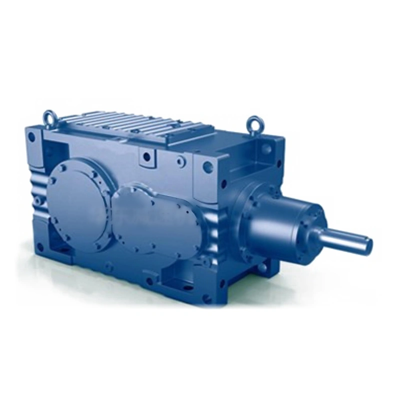
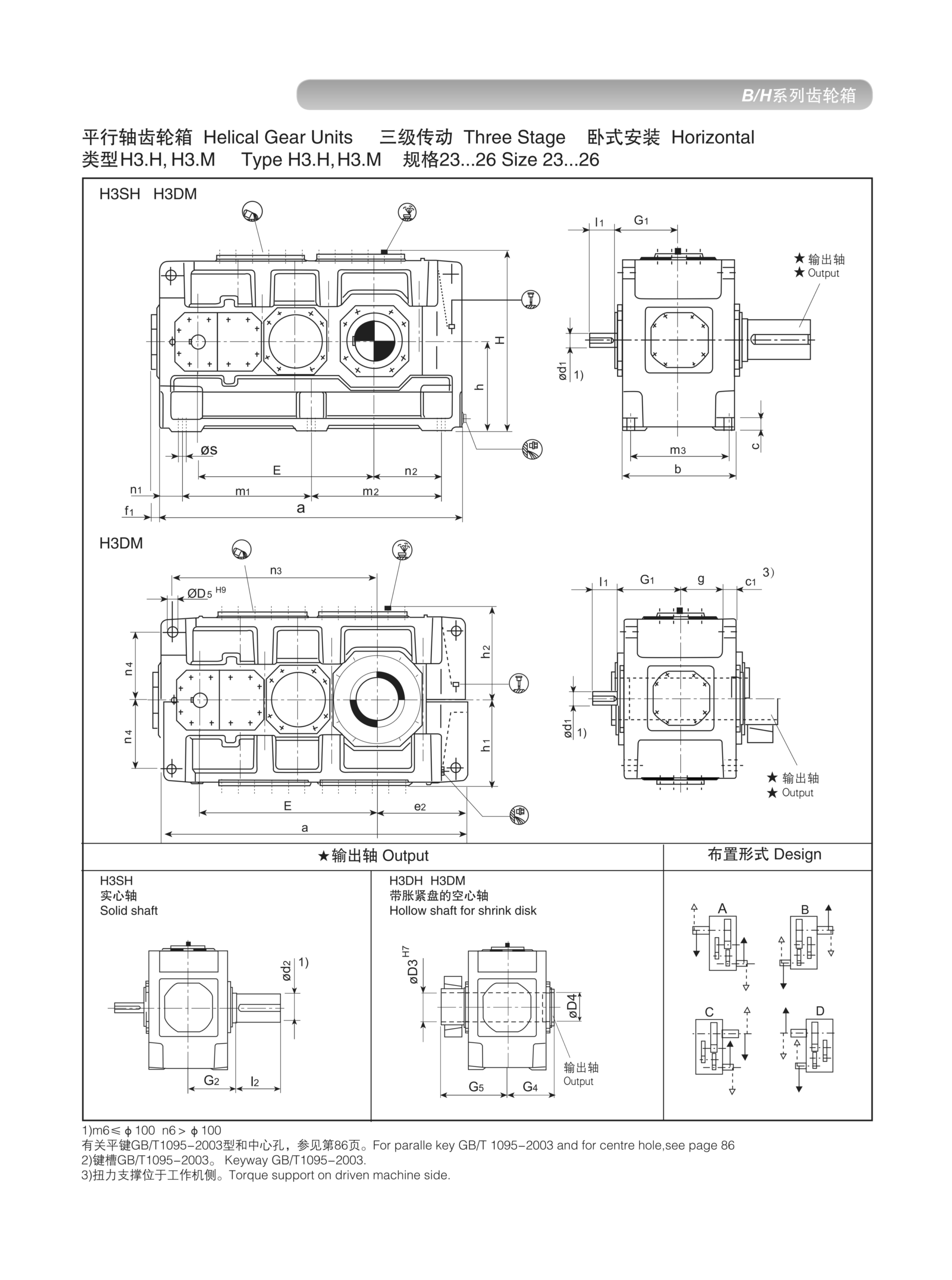
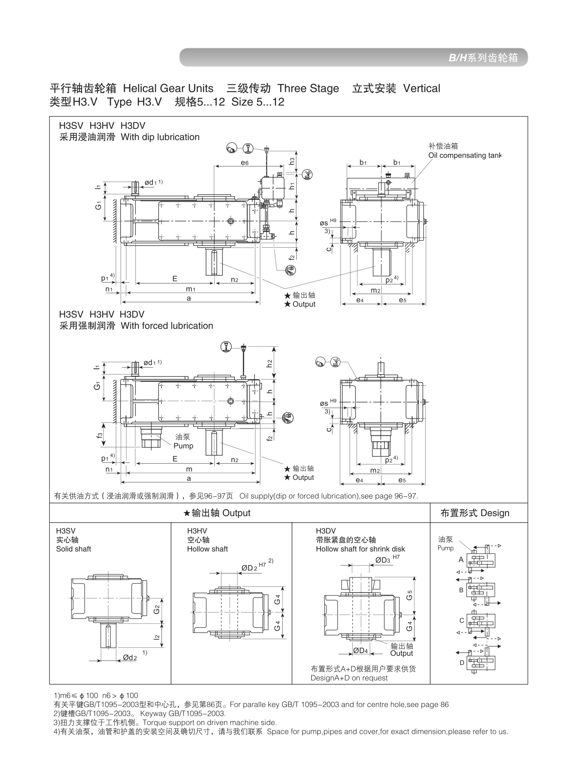
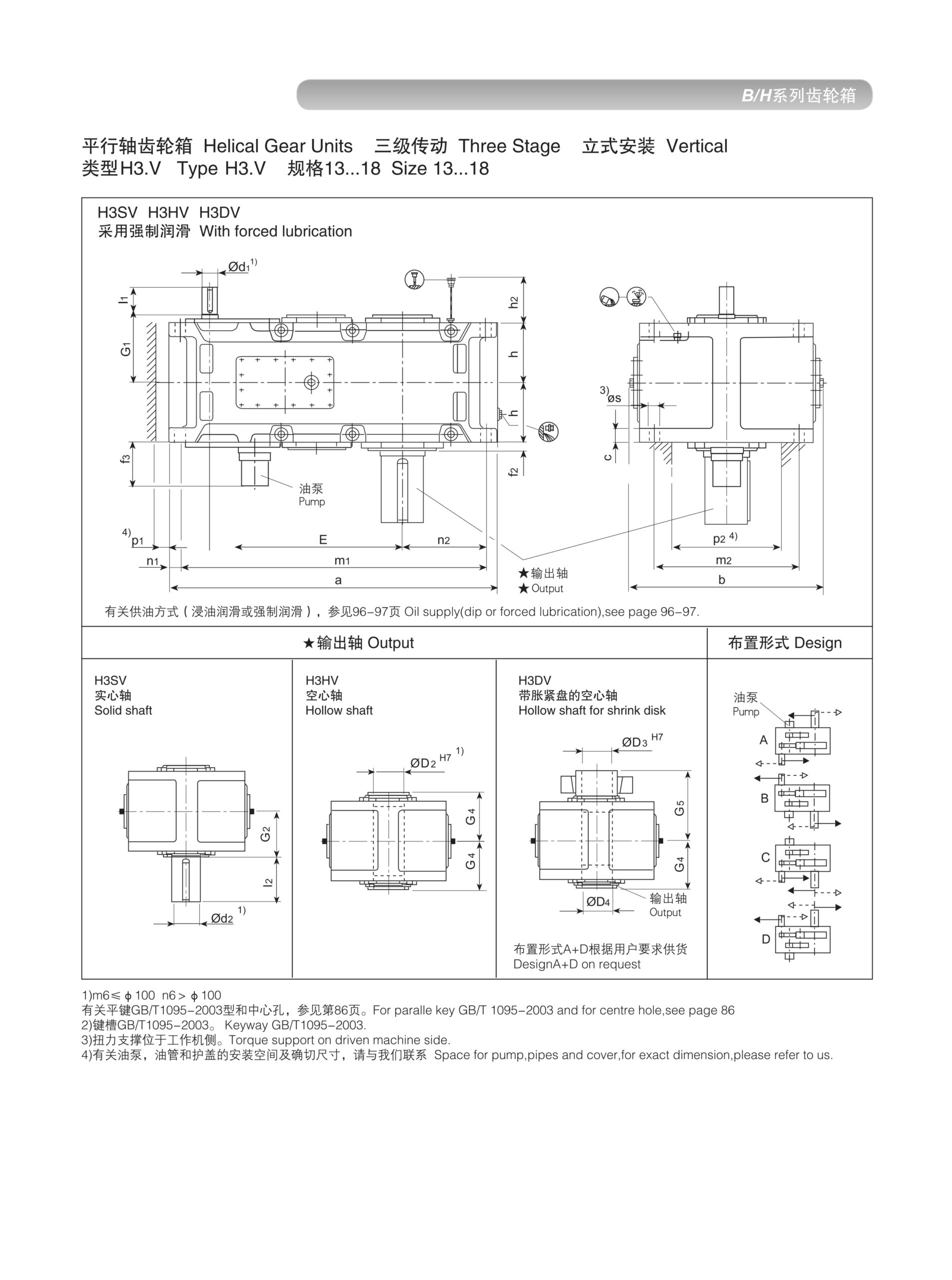
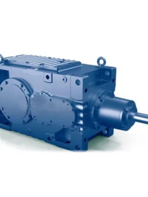
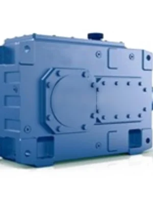
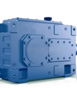
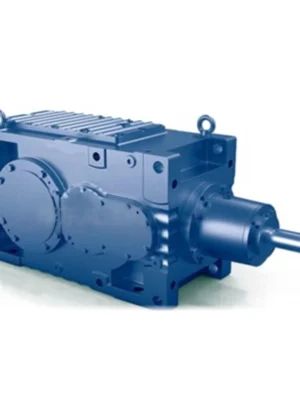
EP-H3 is a three-stage helical parallel-shaft gearbox delivering ratios up to 280:1 and output torques to 200 kNm in sizes 5–26. Built for heavy process industries — cement, mining, wastewater, and chemical — where very low shaft speeds and high continuous torque are essential.
MOQ: Flexible. Minimum order value USD 1,500; mixed orders and trial quantities welcome.
Three helical stages delivering ratio depth from 25:1 to 280:1 — engineered for the heaviest slow-speed process drives up to 200 kNm. Sizes 5–26.
The EP-H3 is the three-stage member of the HB helical inline gearbox family, designed for the class of drives where extremely low output speeds and high output torques must coexist within an in-line parallel-shaft housing. Cement mills, mining conveyors, wastewater sludge thickeners, chemical reactor agitators, and large kiln auxiliary drives all share this requirement — and the EP-H3 was built specifically to meet it.
Three carburised and ground helical gear meshes in series achieve overall ratios from approximately 25:1 to 280:1 across the size range from 5 to 26, with a maximum nominal output torque of 200 kNm at the largest frame. This ratio depth allows a standard 1450 rpm four-pole motor to drive an output shaft turning at as little as 5 rpm continuously — without the complexity or energy losses of a fluid coupling, VFD, or additional gearbox stage stacked in series.
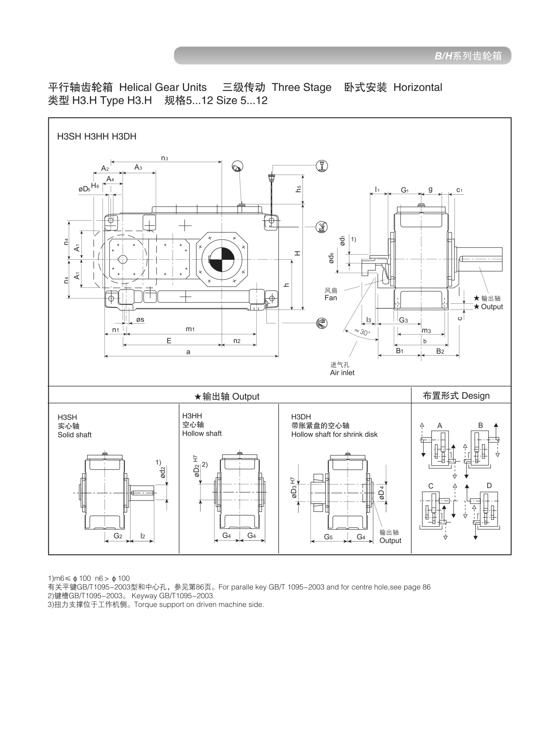
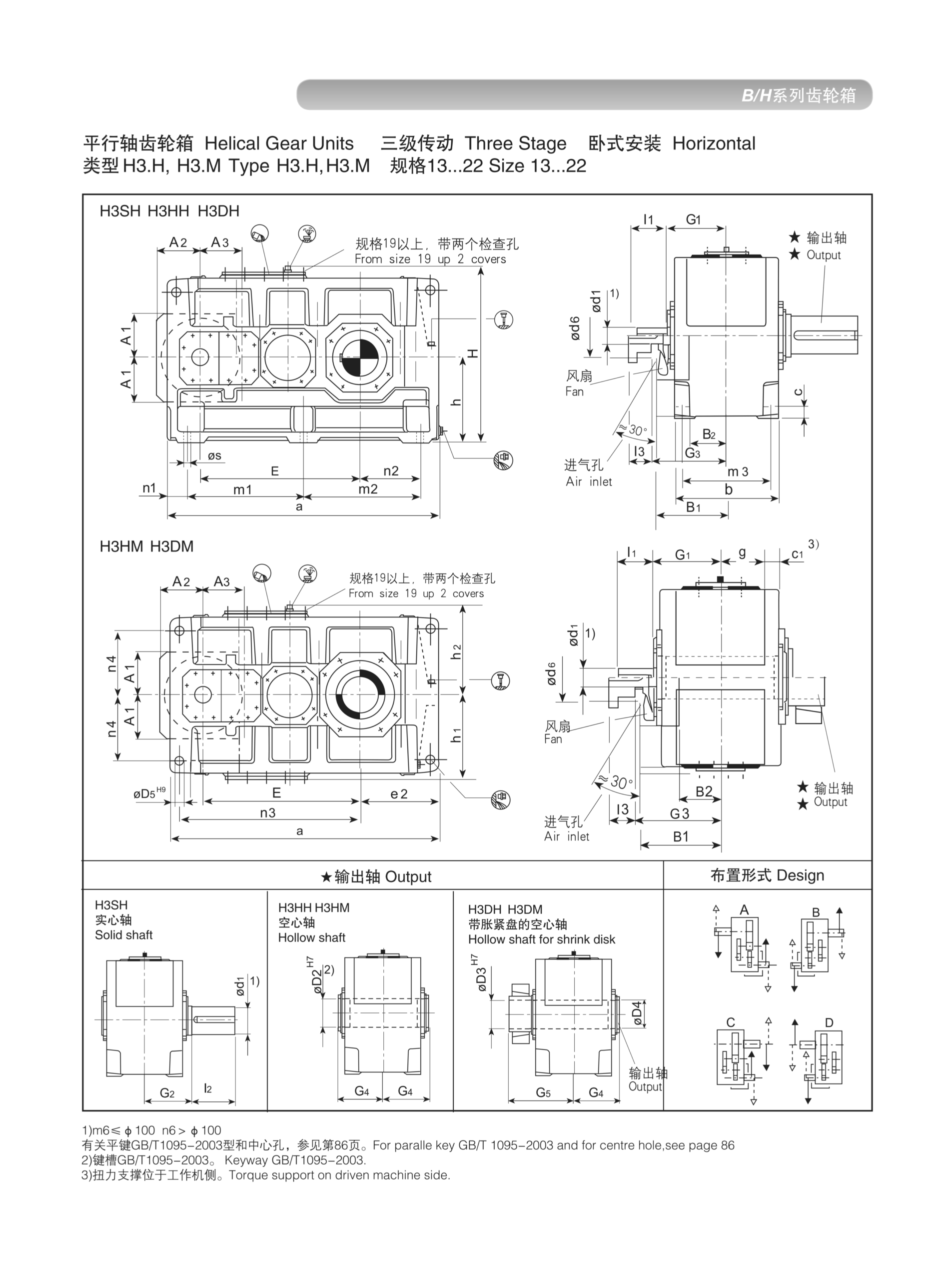
Three dimensional groups are defined for sizes 5–12, 13–22, and 23–26, with separate horizontal and vertical drawing sets, ensuring accurate foundation and interface design for all frame classes.
The addition of a third helical stage serves two distinct engineering purposes. First, it extends the ratio ceiling substantially — from about 45:1 with two stages to 280:1 with three, in a housing that is only modestly longer axially. Second, it allows very large output torques to be generated at very low shaft speeds without oversizing the input motor. At a ratio of 100:1, for example, a 15 kW motor turning at 1450 rpm will produce approximately 10 kNm at the output shaft — a level of torque that would require a much larger, heavier, and more expensive motor at direct-drive or low-ratio speeds.
The three-stage configuration also improves gear mesh efficiency by distributing the total load across three sets of gear teeth, each operating at a moderate load level. While overall efficiency (approximately 95–96% at rated load) is slightly lower than single or two-stage units, this is largely offset by the motor power savings from the high reduction ratio.
For OEMs and plant engineers specifying heavy machinery, the EP-H3 provides a single-unit solution where the alternative would be either a custom gearbox or a two-gearbox series combination — both more expensive and harder to maintain.
EP-H3 spans sizes 5 through 26 with three frame groups. Nominal torque and typical ratio ranges by size:
| Size | Nom. Output Torque (kNm) | Max Input Speed (rpm) | Ratio Range (i) | Applications |
|---|---|---|---|---|
| 5 | 0.50 | ≤1500 | 25–200 | Auxiliary slow drives |
| 7 | 1.10 | ≤1500 | 25–200 | Small agitators, feeders |
| 10 | 2.80 | ≤1500 | 25–200 | Process mixers |
| 13 | 7.50 | ≤1500 | 25–250 | Heavy conveyors, thickeners |
| 16 | 18.0 | ≤1000 | 25–250 | Drum drives, heavy agitators |
| 19 | 45.0 | ≤750 | 25–250 | Kiln auxiliaries, mill drives |
| 22 | 100. | ≤600 | 25–280 | Large industrial mixers |
| 26 | 200. | ≤500 | 25–280 | Mining conveyors, heavy mills |
EP-H3 Horizontal Dimension Drawing — Sizes 5–12
EP-H3 Horizontal Dimension Drawing — Sizes 13–22
EP-H3 Vertical Dimension Drawing — Sizes 5–12
Very low output speeds (<10 rpm) may require forced lubrication or specific housing orientations — consult our technical team.
Three carburised and ground helical gear pairs arranged for optimal load sharing and thermal distribution. Each stage operates at roughly one-third of the total ratio, keeping individual tooth loads within the optimum contact-stress range.
Frame groups 5–12, 13–22, and 23–26 each use optimised housing proportions and bearing arrangements. This avoids the cost of over-specifying to a single large dimensional envelope for all frames.
Standard H3 units use self-contained splash lubrication. For large frames at high input speeds or elevated ambient temperatures, a gear-pump-driven forced lubrication circuit with filter and oil cooler is available, extending thermal capacity significantly.
Three-stage overall efficiency of 95–96% at rated load — achieved through precision-ground gear teeth, quality anti-friction bearings, and close-tolerance assembly. At high ratios, the motor power savings easily outweigh the modest gear losses.
Complete dimensional drawing sets for both H.xxx (horizontal) and V.xxx (vertical) orientations in each size group. Separate drawings reflect the different sealing, oil level, and breather configurations for each orientation.
From cement kiln auxiliary drives and mining conveyor tail shafts to wastewater sludge thickeners and chemical reactor drives — the EP-H3 covers heavy-duty, continuous-service applications across virtually every heavy process industry.
| Industry | Application | Primary Requirement |
|---|---|---|
| Cement & Lime | Kiln auxiliary, cooler drives, elevator drives | Very high ratio, shock tolerance |
| Mining | Long-distance conveyor head/tail drives | High torque, 24/7 duty |
| Steel | Rolling mill auxiliary, cooling bed | High reduction, low vibration |
| Wastewater | Sludge thickeners, slow rake drives | Very low speed, sealed housing |
| Chemical | Large reactor agitators, polymerisation | Continuous duty, long MTBF |
| Power Generation | Coal handling, ash conveying | High shock, reversing loads |
The EP-H3 is predominantly specified in continuous-duty installations where the gearbox runs 24 hours per day, 365 days per year. Its design safety margins are calculated for these duty profiles — not intermittent or light-duty cycles that would allow a smaller unit to be used.
Where does EP-H3 fit in the helical inline gearbox family?
| Model | Stages | Ratio Range | Max Torque | Typical Sector |
|---|---|---|---|---|
| EP-H1 | 1 | Up to 6.3:1 | 3.6 kNm | Compact drives, packaging, HVAC |
| EP-H2 | 2 | 6.3–45:1 | 90 kNm | Process plant, conveyor, mixers |
| EP-H3 | 3 | 25–280:1 | 200 kNm | Heavy process, mining, cement |
| EP-H4 | 4 | 50–500:1 | 500 kNm | Extremely slow drives, large mills |
If your ratio requirement falls between 25:1 and 280:1 and your output torque is up to 200 kNm, the EP-H3 is the correct member of the helical series to specify. For ratios above 280:1, proceed to EP-H4.
Provide your required output torque, ratio, ambient conditions, and mounting orientation. Our team delivers a confirmed size recommendation and quotation within one business day.
Audible noise is evidence to investigate, but fault location depends on whether the sound tracks speed, torque or the machine structure.
Flexible couplings accommodate limited relative movement, but poor shaft alignment still affects bearings and seals.
Oil observed on a housing may have traveled from a vent, joint or shaft seal; finding the first wet point is essential.