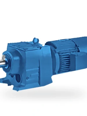
Audible noise is evidence to investigate, but fault location depends on whether the sound tracks speed, torque or the machine structure.
Helical Gearbox Noise Diagnosis by Speed and Load
read more

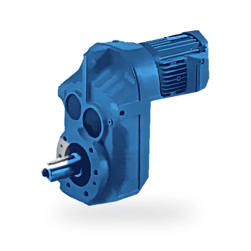
The EP-F77 is a 3-stage parallel-shaft helical gear reducer delivering up to 1,900 N·m output torque from 0.18–15 kW across gear ratios 4.92–73.34. Available in foot-mount (F), flange-mount (FF), hollow-bore (FA), flange+hollow (FAF), and torque-arm (FAT) configurations — engineered for quiet, efficient, long-service industrial drive applications.
MOQ: flexible. Minimum order value USD 1,500; mixed orders and trial quantities welcome.
Bulk-handling industries — cement, grain, fertiliser, and building materials — require gear reducers that can sustain high torque for extended periods without demanding attention. The EP-F77 parallel-shaft helical gear reducer is designed for exactly this service profile, delivering up to 1,900 N·m continuous torque from 0.18–15 kW inputs across ratios of 4.92–73.34, with a three-stage helical gear train engineered for 40,000 hours of reliable operation.
Screw conveyors, bucket elevators, and drag-chain feeders all share a common duty pattern: high starting torque followed by sustained moderate load. The EP-F77 is sized with service factors appropriate for this profile, with bearing selection based on L10h life calculations that account for the actual torque time-history rather than just peak torque. This approach results in a correctly-sized unit that neither overshoots on cost nor undershoots on life.
The EP-F77 is compatible with IEC-standard B14 and B5 motor flanges, simplifying motor sourcing. FA77 and FAT77 hollow-shaft variants allow the gearbox to slip directly onto a conveyor head-shaft, eliminating the shaft-to-shaft coupling that corrodes and requires periodic replacement in dusty environments. Browse our full range at the Ever Power product homepage.
| Parameter | Specification |
|---|---|
| Gear Type | Multi-stage parallel-shaft helical gears, precision-ground DIN 6/ISO 6 |
| Number of Stages | 3-stage |
| Motor Power Range | 0.18–15 kW |
| Max Output Torque | 1,900 N·m |
| Gear Ratio Range | 4.92–73.34 |
| Output Speed Range | 20–285 rpm |
| Approximate Unit Weight | 35–55 kg |
| Max Output Radial Load | 13,200 N |
| Transmission Efficiency | ≥ 96% per stage (overall ≥ 92% for 2-stage, ≥ 88% for 3-stage) |
| Lubrication | Splash lubrication; ISO VG 220 mineral oil (factory fill) |
| Housing Material | Close-grained cast iron (HT250 / EN-GJL-250) |
| Gear Material | Case-hardened alloy steel (20CrMnTi / 20MnCr5), HRC 58–62 |
| Protection Rating | IP55 standard; IP65 optional |
| Ambient Temperature | −25 °C to +45 °C (standard lubricant) |
| Noise Level | ≤ 72 dB(A) at rated load (1 m, free-field) |
| Standards Compliance | ISO 6336, DIN 3990 gear rating; ISO 281 bearing life; CE Machinery Directive |
The F77 series is available in multiple structural types to suit different installation geometries and driven-machine interfaces. All types share the same internal gear set and achieve identical torque and efficiency ratings; the differences lie in mounting method and output connection.
| Type Code | Description |
|---|---|
| F77 | foot-mounted, solid output shaft |
| FF77 | B5 flange-mounted, solid output shaft |
| FA77 | shaft-mounted, hollow output shaft |
| FAF77 | B5 flange + hollow output shaft |
| FAT77 | torque-arm, hollow output shaft |
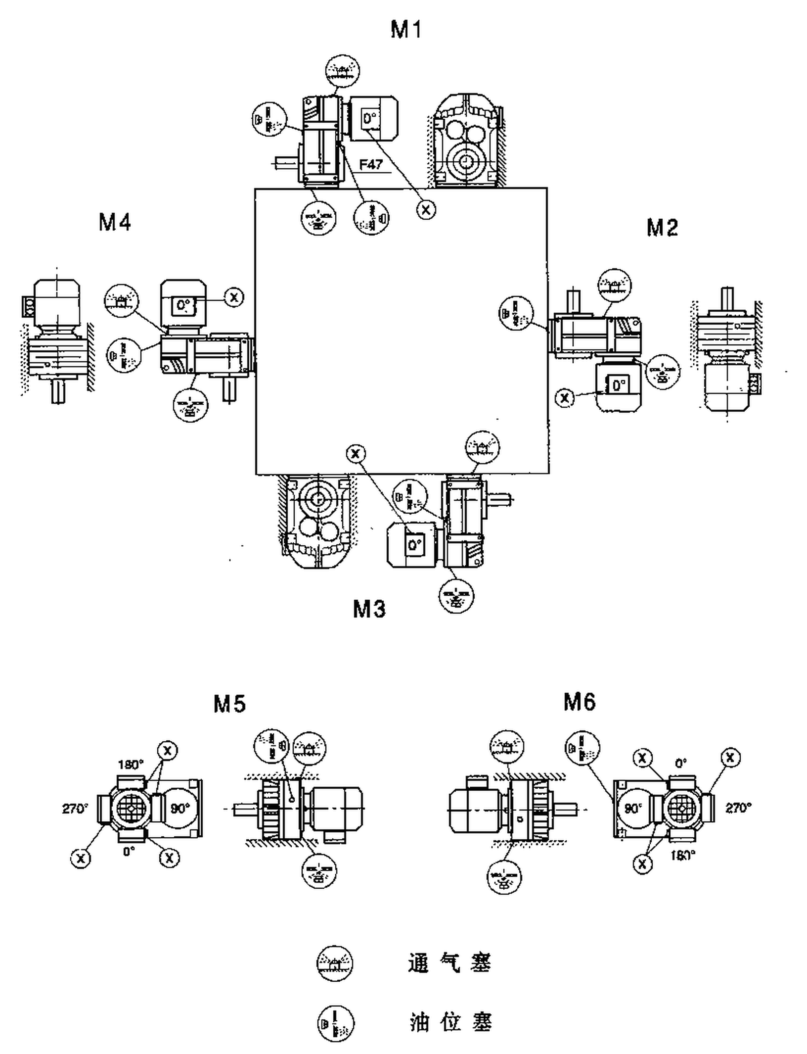
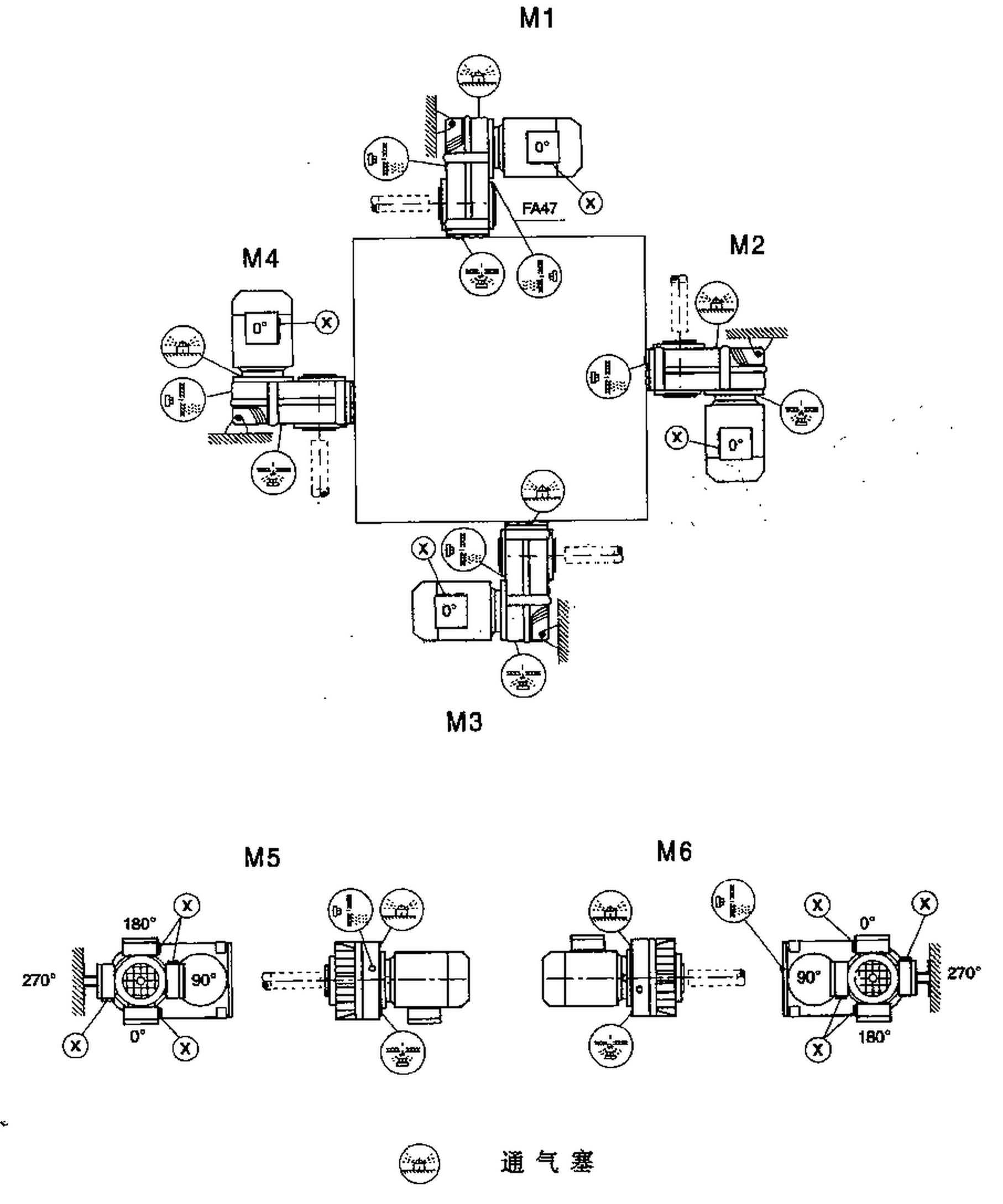
All F77 structural types support six standard mounting positions (M1 through M6), defined by the angular orientation of the output shaft relative to the horizontal. Oil fill level and vent plug position must be adjusted for each mounting position; refer to the installation manual for position-specific fill quantities and the correct vent-plug orientation.
Each gear stage delivers ≥96% mechanical efficiency through precision-ground helical flanks and optimised tooth profile corrections. Compared with worm reducers of equivalent output torque, the EP-F77 typically saves 15–35% in electrical energy over the same duty cycle — a saving that often exceeds the gearbox purchase price within two years.
With up to 1,900 N·m from a housing sized for 0.18–15 kW, the EP-F77 achieves torque density competitive with bevel-helical units of the same output-shaft diameter. The case-hardened alloy-steel gears (HRC 58–62) sustain high Hertzian contact stress without case fatigue, enabling compact dimensions even at the upper end of the power range.
Bearings are selected for a minimum L10h life of 20,000 hours at rated conditions and verified by ISO 281 calculation using actual application load spectra. Precision-ground gears eliminate the geometric errors that cause micro-pitting, extending tooth-flank life to typically 40,000 hours or more when correctly lubricated.
Five standard structural types — F, FF, FA, FAF, FAT — and an input-shaft-only FA-SZ variant address virtually every machine interface geometry without custom engineering. The FA and FAT hollow-bore types eliminate external couplings entirely, reducing drivetrain length and eliminating one routine maintenance item.
Helical gear engagement produces a progressive, distributed contact zone rather than the sudden full-face mesh of spur gears. This characteristic, combined with profile-ground tooth flanks and dynamically balanced rotating components, keeps noise levels below 72 dB(A) at 1 m — important in operator-occupied environments and buildings with vibration-sensitive equipment.
The parallel-shaft geometry keeps the overall drive envelope short in the radial direction, allowing direct-couple installation in machine frames where right-angle units would require a longer cantilevered arrangement. The F77's small envelope also reduces the inertia of the stationary drive assembly, which matters in frequent-cycle indexing applications.
The diagrams below show the external geometry and connection interfaces for each structural type in the F77 family. Use these to confirm mounting space requirements and driven-machine interface compatibility before finalising your order.
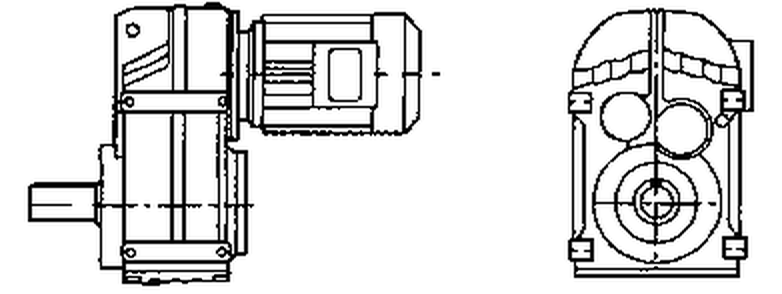
F77 Standard Foot-Mount (Solid Output Shaft)
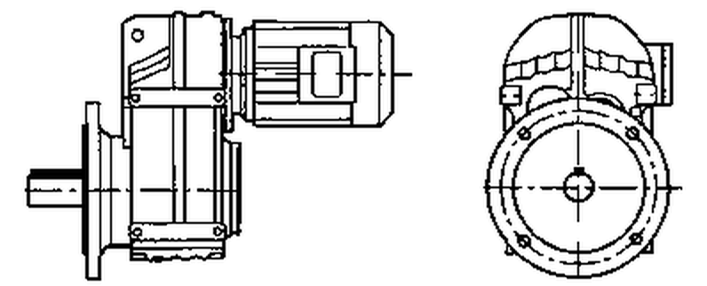
FF77 Flange-Mount (Solid Output Shaft)
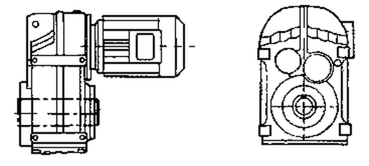
FA77 Shaft-Mounted (Hollow Output Bore)
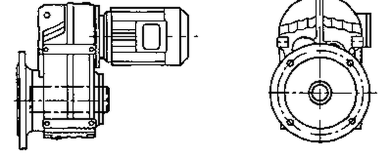
FAF77 Flange + Hollow Bore
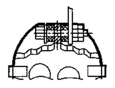
FAT77 Torque-Arm (Hollow Bore)
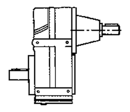
FA77-SZ Input Shaft Only
| Industry Sector | Typical Application |
|---|---|
| Building Materials | Cement screw conveyors, bucket elevator heads, and plate-feeder slow drives in aggregate plants. |
| Paper & Pulp | Washing press rolls, screen cylinder drives, and broke-pulper auxiliary drives. |
| Grain & Feed Milling | Hammer mill pre-feeders, pellet-press die plate drives, and bulk loading arms. |
| Metal Stamping | Transfer bar and coil reel drives on progressive-die stamping lines. |
A cement works replaced three chain-drive-and-gearbox combinations on its raw meal screw conveyors with EP-F77 direct-coupled in-line reducers. Start-up current peaks fell by 30%, and the maintenance interval for oil changes extended from 6 months to the recommended 15,000 hours, cutting annual downtime by over 60 hours.
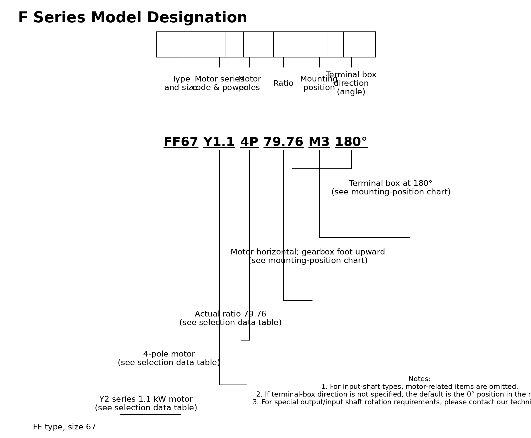
The model code contains all ordering information required for production. An example order code for a torque-arm, hollow-bore, 7.5 kW unit is:
EP - F77 - FAT - Y - 3 - 7.5 - 4P - M1
| Code Element | Meaning |
|---|---|
| EP | Brand identifier — Ever Power |
| F77 | Series and frame size |
| FAT | Structural type: torque-arm, hollow-bore output |
| Y | Motor type: Y-series IEC standard induction motor |
| 3 | Number of gear stages |
| 7.5 | Motor rated power in kW |
| 4P | Motor pole count (1,450 rpm at 50 Hz) |
| M1 | Mounting position |
EP-F77 units are stocked in the most popular ratios to support unplanned replacements and urgent project timelines. Contact our sales team for current stock levels, expedited shipping options, and tailored frame agreements for facilities management organisations.
Audible noise is evidence to investigate, but fault location depends on whether the sound tracks speed, torque or the machine structure.
Flexible couplings accommodate limited relative movement, but poor shaft alignment still affects bearings and seals.
Oil observed on a housing may have traveled from a vent, joint or shaft seal; finding the first wet point is essential.