Audible noise is evidence to investigate, but fault location depends on whether the sound tracks speed, torque or the machine structure.
Helical Gearbox Noise Diagnosis by Speed and Load
read more

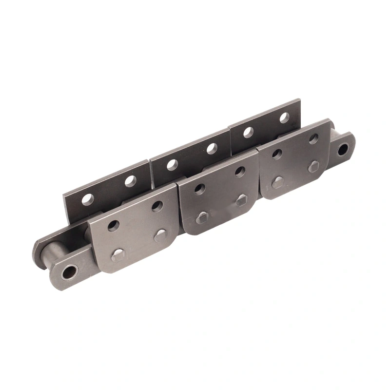
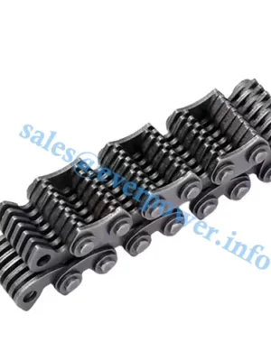
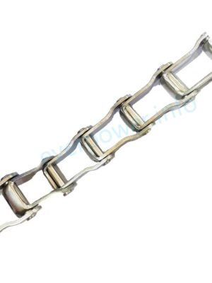
A four-configuration 50.8mm trencher chain family for drawing-led replacement. Compare SC, RC, S and R codes, rivet forms and attachment dimensions.
MOQ: flexible. Minimum order value USD 1,500; mixed orders and trial quantities available.
The 50.8mm EP-CHK50A series includes four closely related but separately named chain entries. A buyer may see the same pitch and roller dimensions in all four and conclude that a shortened designation is enough. That assumption is risky. The actual order should specify EP-CHKSC50A001, EP-CHKRC50A001, EP-CHKS50A001 or EP-CHKR50A001 in full, together with its rivet head type and the required supply scope.
The technical reference provides an extensive matrix including side-plate thicknesses, attachment width, hole dimensions, rivet form, a tensile figure and a weight-per-metre figure. It does not fully explain every difference encoded in the SC versus S naming. This page therefore helps purchasing and maintenance teams compare published facts while retaining questions that must be settled by a confirmed part drawing.
Models
4
Hole d3
13.48 mm
Chain and plate geometry
| EP Model | Pitch P (mm) | Roller d1 (mm) | Pin d2 (mm) | Plate T1 (mm) | Plate T2 (mm) | W (mm) | W1 (mm) | W2 (mm) |
|---|---|---|---|---|---|---|---|---|
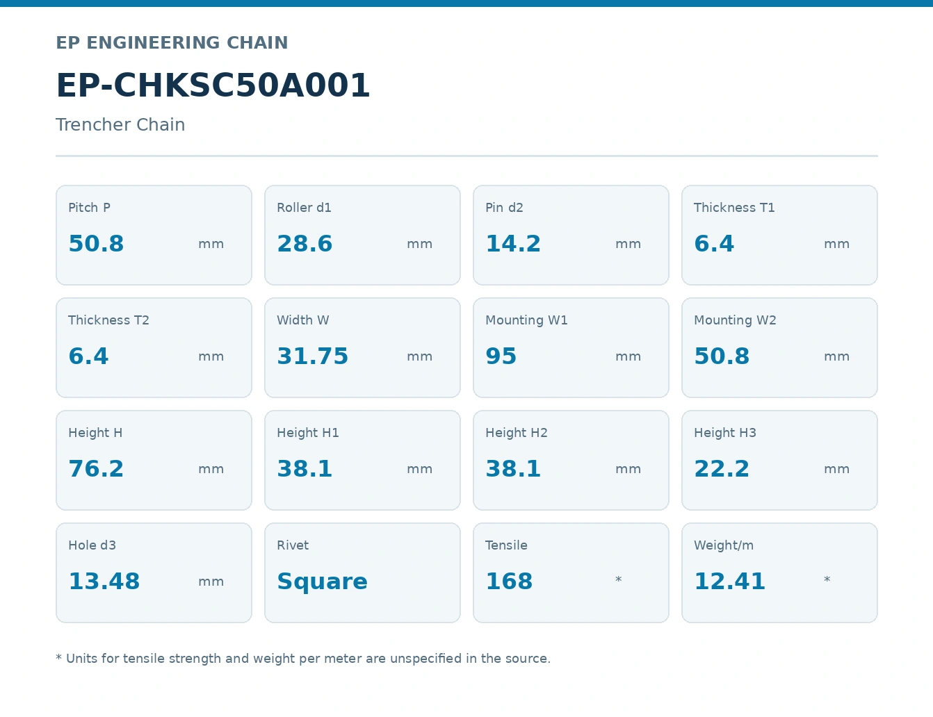
| EP-CHKSC50A001 | 50.8 | 28.6 | 14.2 | 6.4 | 6.4 | 31.75 | 95 | 50.8 |
| EP-CHKRC50A001 | 50.8 | 28.6 | 14.2 | 6.4 | 6.4 | 31.75 | 95 | 50.8 |
| EP-CHKS50A001 | 50.8 | 28.6 | 14.2 | 6.4 | 6.4 | 31.75 | 95 | 50.8 |
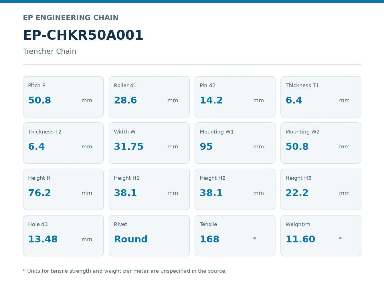
| EP-CHKR50A001 | 50.8 | 28.6 | 14.2 | 6.4 | 6.4 | 31.75 | 95 | 50.8 |
Mounting and catalogue reference values
| EP Model | H (mm) | H1 (mm) | H2 (mm) | H3 (mm) | Hole d3 (mm) | Rivet head | Avg tensile* | Weight/m* |
|---|---|---|---|---|---|---|---|---|
| EP-CHKSC50A001 | 76.2 | 38.1 | 38.1 | 22.2 | 13.48 | Square | 168 | 12.41 |
| EP-CHKRC50A001 | 76.2 | 38.1 | 38.1 | 22.2 | 13.48 | Round | 168 | 12.41 |
| EP-CHKS50A001 | 76.2 | 38.1 | 38.1 | 22.2 | 13.48 | Square | 168 | 11.60 |
| EP-CHKR50A001 | 76.2 | 38.1 | 38.1 | 22.2 | 13.48 | Round | 168 | 11.60 |
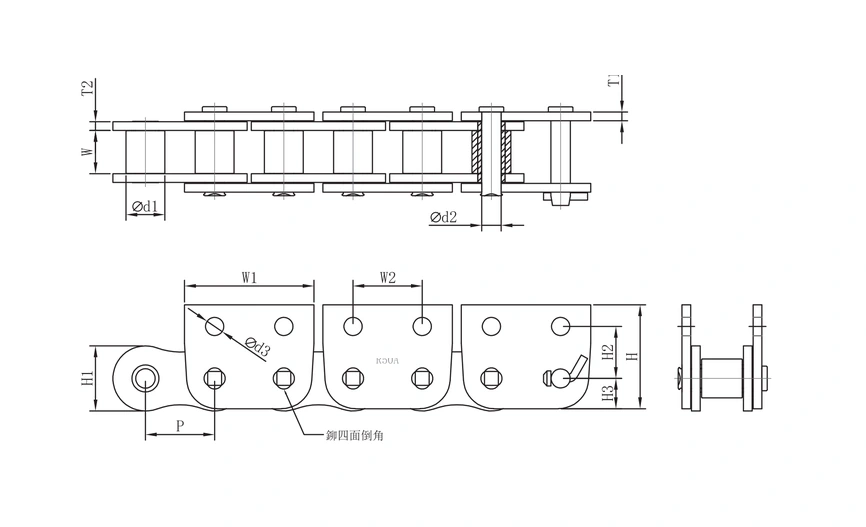
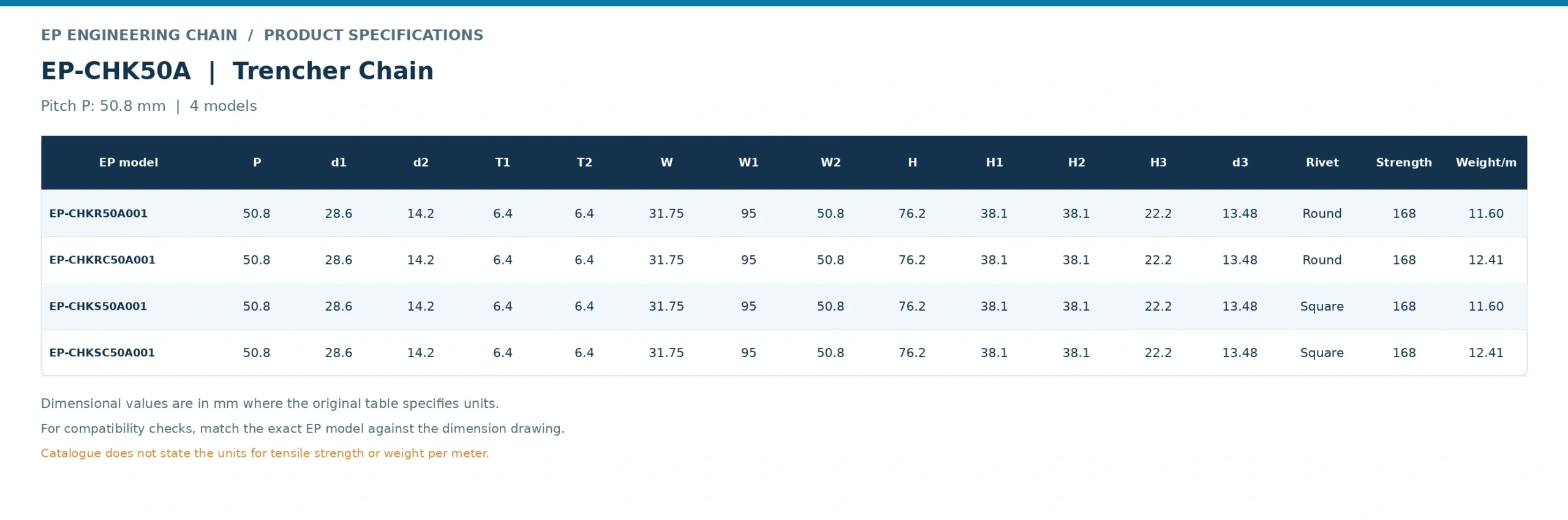
The W figure appears with rounding at 31.8 in a repeated table; the detailed value 31.75 is retained pending critical-fit confirmation. Strength and weight units are not stated.
The supplier catalogue organizes other industrial link types in the industrial chain range.
The SC and S rows are both associated with a square rivet-head form, while RC and R are associated with a round rivet-head form. Within the source, the SC/RC entries show a listed weight-per-metre figure of 12.41 and the S/R entries show 11.60. The units are absent. Those different entries prove that the source distinguishes the configurations, but do not by themselves establish precisely which manufacturing, plate or assembly feature accounts for the change.
Avoid replacing an S model with an SC model or vice versa solely because the basic drawing dimensions appear identical. Instead, request confirmation of the exact model suffix, the intended mounting arrangement and any associated accessory requirements. When building a price comparison, keep all four model codes as separate lines so that a commercial substitution cannot occur unnoticed.
All four published 50A models are listed at P = 50.8mm, d1 = 28.6mm and d2 = 14.2mm. The two specified plate thicknesses T1 and T2 are each 6.4mm. Additional dimensions include W = 31.75mm, W1 = 95mm, W2 = 50.8mm, H = 76.2mm, H1 = 38.1mm, H2 = 38.1mm and H3 = 22.2mm, plus d3 = 13.48mm.
The W entry appears rounded to 31.8mm in a repeated table of the same source. Because the distinction is consistent with rounding rather than a confirmed technical change, this page retains 31.75mm as the detailed listed value and recommends confirmation against a production drawing when the width is a tight-fit dimension. Never invent an additional tolerance to explain an unqualified table value.
A shared 50.8mm pitch does not make SC, RC, S and R interchangeable. Keep the complete suffix on the order and verify what the configuration includes.
The 13.48mm hole figure should be considered alongside the orientation of the attachment plate, the hole positions and the type of fastening hardware required for the digging tool. A matching chain pitch is of limited use if the cutting accessory cannot be fitted at the correct position. Check the bolt or pin system provided by the equipment builder and record whether a holder is reusable.
Inspect holes on an old chain for oval wear, deformation around the edge or damage caused by loose fasteners. Reproducing a worn diameter as the nominal specification can create an incorrectly loose connection. Use a new-part drawing when available and distinguish a design size from a field measurement.
Before preparing a complete assembly quotation, map the cutting tool sequence around the chain loop. A trencher can use a specific pattern of elements and offsets that is not captured by the bare chain code. The machine model alone is not a sufficient substitute for the chain drawing where it has undergone prior modifications.
A practical enquiry shows the existing chain against its sprocket, the shape of the attachment, and an overall boom photograph. Indicate the link count, tooth holder arrangement, and whether the requirement is chain alone or a fitted chain assembly. These distinctions are especially important for buyers replacing only damaged sections rather than the entire cutting run.
The 50.8mm trenching run should be evaluated with its installed sprocket constructions; verify the tooth geometry and local mounting arrangement from the actual machine rather than assuming a catalogue match.
The catalogue prints an average tensile strength value of 168 across the 50A entries. It also prints the 12.41 and 11.60 weight values described above. The relevant units and test conditions are not established by the source. It would therefore be misleading to label the 168 figure as a safe operating force or claim that the lower listed weight automatically means a lower service rating.
For an engineering load review, provide the tension scenario, expected shock loading, cutting conditions, duty cycle and machine documentation. A finished chain can then be discussed with the required evidence in view. Product marketing should not treat a single unqualified strength figure as a warranty about trench depth, ground type or useful life.
The documented rivet-head forms are square for SC and S, and round for RC and R. The source also lists different weight figures for the two pairs. Beyond those documented distinctions, the exact construction differences should be confirmed by drawing.
The published d3 is 13.48mm in all four rows. That number should be reviewed with W, W1, W2 and the H-family coordinates because hole diameter alone does not define the mounting pattern.
No. It appears under an average tensile-strength heading without a stated unit or test condition. A safe operating or shock-load limit requires a separate approved technical basis.
Mixed-model orders can be discussed when each line is clearly defined. MOQ is configuration-dependent; suitable first buyers may request 1-5 samples. 1-2 pieces can cost more per unit, and combined orders normally aim for an approximate USD 1,500 minimum value.
Indicative lead-time groups are 10-25 working days for standard items, 20-45 for customized components and 45-120 for project-level equipment. EXW/FOB/CIF/DAP are normally available for discussion; FCA/CFR/CPT/CIP/DDP are assessed against the final shipment plan.
Give the full SC, RC, S or R suffix and specify whether the cutting tools are included. Ever Power can discuss the individual 50A variant rather than merging distinct order lines into an unclear generic description.
Resolve My EP-CHK50A Model Configuration
Audible noise is evidence to investigate, but fault location depends on whether the sound tracks speed, torque or the machine structure.
Flexible couplings accommodate limited relative movement, but poor shaft alignment still affects bearings and seals.
Oil observed on a housing may have traveled from a vent, joint or shaft seal; finding the first wet point is essential.