
Losses leave the gearbox as heat, and allowable oil temperature depends on both the duty and the surroundings. This arithmetic is not a thermal rating and does not specify where each loss occurs. Refer to the continuous gearbox heat balance guidance. Identify gearbox input power, oil state, motor contribution and uncertainty. Assess the maker thermal limit for the actual environmental boundary.
Quantify heat-generation order of magnitude
Consider lubricant viscosity effects
Perform thermal acceptance at operating load
Quantify heat-generation order of magnitude
Mechanical power not delivered to the output becomes losses in the overall gearbox system; at 15 kW input and an illustrative 95 percent unit efficiency, about 0.75 kW is dissipated as heat.
This arithmetic is not a thermal rating and does not specify where each loss occurs; estimate losses using efficiency at the actual torque and speed.
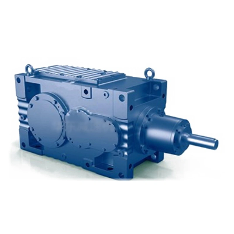
Identify gearbox input power, oil state, motor contribution and uncertainty; use manufacturer-specific thermal data when assessing the ability to reject the heat; a high mechanical rating can coexist with insufficient external cooling.
Characterize ambient air
Heat rejection decreases when surrounding air or neighboring equipment is hot; a gearbox inside a closed machine room is not cooled like a standalone unit in a ventilated workshop.
An ambient stated at the factory does not describe every installation; log expected air temperatures at the gearbox, not only the outdoor weather.
Identify enclosure panels, sunlight, adjacent motors and airflow paths; assess the maker thermal limit for the actual environmental boundary; a room-temperature trial may underpredict summer oil temperature.
Measure continuous and cyclic conditions
A short run raises the housing temperature but may not approach steady state; an agitator used for an eight-hour batch can behave differently from a five-minute indexing machine.
A quick infrared reading is not sufficient to certify sustained service; record continuous torque, operating hours, starts and idle intervals.

Track temperatures across representative full production cycles; use a stabilized or otherwise justified thermal comparison accepted by the supplier; premature sign-off can miss a slow heat accumulation problem.
Examine mounting and oil distribution
Installation orientation changes oil levels and sometimes the internal lubrication route; a vertical output drive could place an upper bearing above the normal splash region.
A horizontal fill assumption may not carry across mounting codes; specify exact shaft orientation and model configuration before estimating heat.
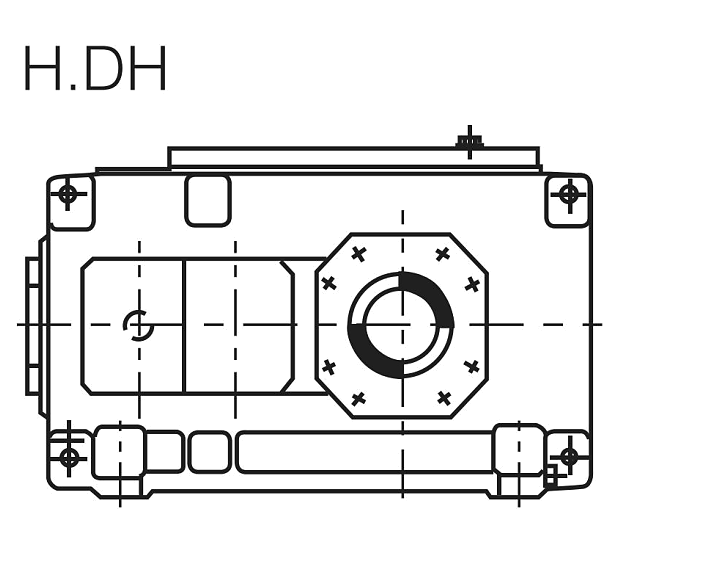
Obtain oil quantity, vent locations and bearing lubrication instructions; approve thermal behavior for that specific spatial installation; a thermally suitable body can still require special bearing oil delivery.
Consider lubricant viscosity effects
Oil viscosity influences churning losses as well as film formation at bearings and gear contacts; an unapproved viscosity change might reduce one loss while worsening protection of loaded surfaces.
Changing oil grades based on heat alone may create new failure modes; read approved lubricant grade and expected operating temperature limits.
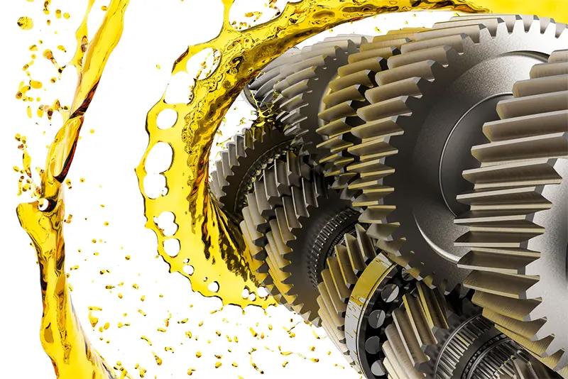
Record oil age, moisture, particle contamination and any additives; choose only lubricants authorized for the exact reducer; a low apparent temperature is not proof of adequate tooth-surface lubrication.
An unapproved viscosity change might reduce one loss while worsening protection of loaded surfaces. Changing oil grades based on heat alone may create new failure modes. Examine the continuous gearbox heat balance layout example. Record oil age, moisture, particle contamination and any additives. Choose only lubricants authorized for the exact reducer.
Evaluate airflow before cooling equipment
Free convection and any fan-assisted airflow depend on the installation clearance; a close-fitting metal guard can reduce airflow even if the motor fan works normally.
Adding a fan without locating its airflow path may accomplish little; inspect vents, guard spacing and external surfaces for accumulated dirt.
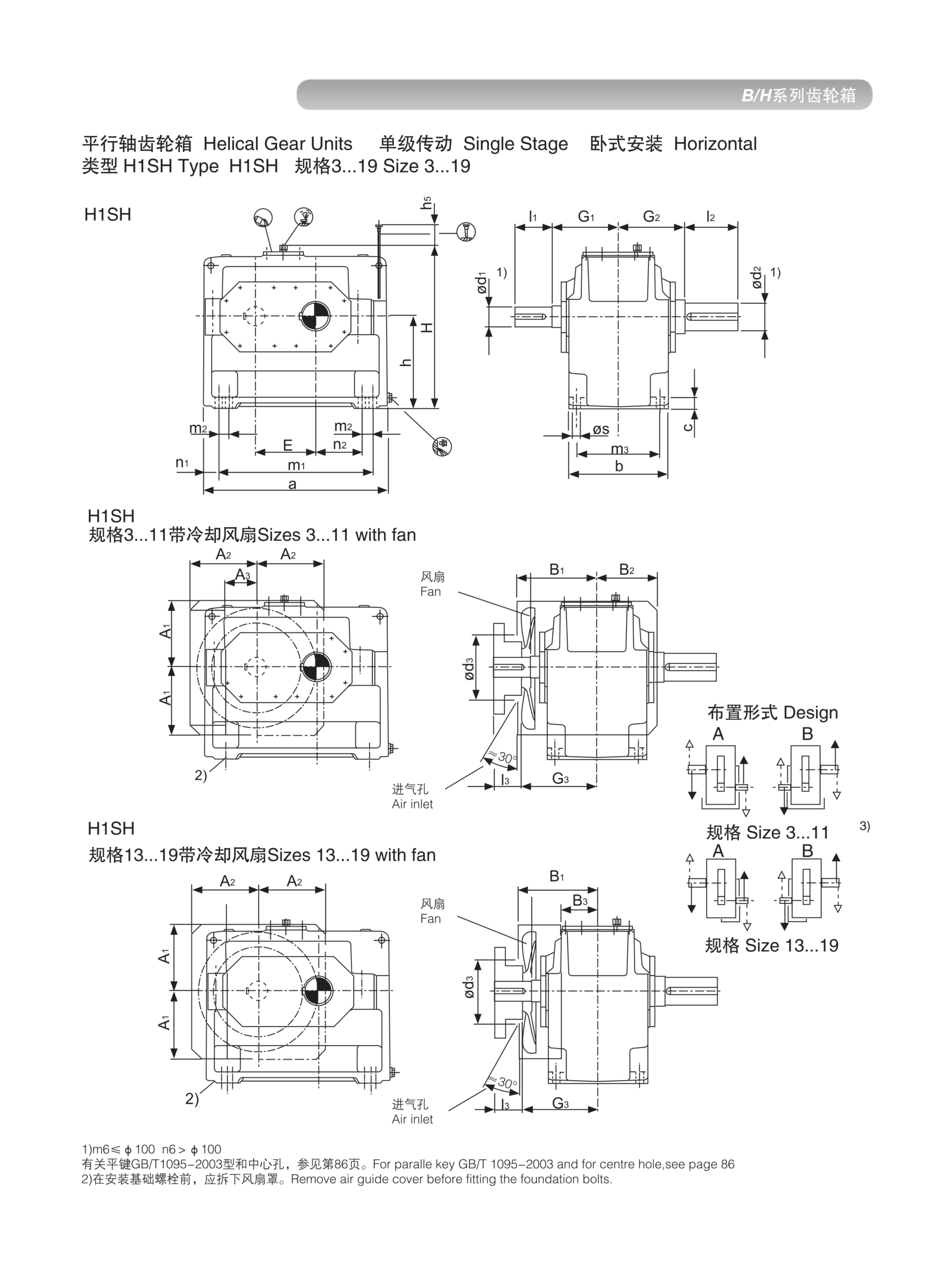
Measure air movement and compare full-load temperature before and after changes; select an appropriate cooling arrangement based on verified lost-power demand; cooling hardware without a rated design may complicate reliability.
Treat oil coolers as a system change
External circulation requires pump, filter, piping and failure monitoring; a cooler fitted in the field can introduce leaks and oil cleanliness risks.
An improvised oil circuit can fail even when thermal calculations look attractive; determine required heat removal and permissible system pressure and flow.
Ask for manufacturer-approved oil circulation connections and monitoring; approve cooling equipment and protective alarms as one engineered package; a cooling retrofit is not just an extra radiator attached to a reducer.
Perform thermal acceptance at operating load
Final thermal evidence comes from a defined measured condition with test boundaries; the target load, rpm, ambient and duration should accompany each recorded temperature.
A single casing measurement without context can mislead a service team; log stable output duty, oil and housing temperature and motor load.
Check measuring device placement and permit for the local environment; accept only results that meet the exact approved condition and limits; comparable trend data also gives maintenance a baseline for future deterioration.
Illustrative engineering scenario: A process drive running for long periods inside a plant enclosure
A hypothetical continuous conveyor reducer receives 15 kW of mechanical power. If the assumed overall gear unit efficiency at the studied condition is 95 percent, the difference between input and output power is 0.75 kW. That loss will ultimately have to leave the assembly as heat, though the calculation does not describe how much is lost at each bearing, seal or gear mesh. The estimate is useful for understanding why a drive that meets mechanical torque demand can still run too warm. It is not a thermal-capacity rating for any named unit. The correct manufacturer capacity needs mounting, speed, ambient, lubricant and enclosure conditions.
The gearbox in this exercise sits behind a close-fitting safety cover, and the ambient near the housing is higher than the room thermostat reading. There is limited air motion, and a large motor sits nearby. Before choosing cooling hardware, maintenance checks that the oil level is correct for the actual mounting orientation and that dust has not blanketed the case. A validated oil specification and a long-enough temperature record are necessary. Measuring the housing immediately after startup does not show what will happen through an eight-hour loaded shift. With stable recorded load, the oil and case temperature can be compared against the equipment manufacturer's specified limits.
If a temperature problem remains, the designer evaluates ventilation, allowable fans and any approved oil circuit. A retrofit cooler requires not only a heat exchanger but also compatibility with the housing, filtration, oil pressure and monitoring of flow failures. The approval file should state which variables were measured and which are modeled. In particular, changing oil viscosity or adding an external pump without the maker's consent is not a substitute for validating the system. A successful test reproduces actual load and the hottest credible surrounding condition rather than an attractive laboratory snapshot.
Five-stage review for a process drive running for long periods inside a plant enclosure
-
Quantify heat-generation order of magnitudeEstimate losses using efficiency at the actual torque and speed. Use manufacturer-specific thermal data when assessing the ability to reject the heat.
-
Characterize ambient airIdentify enclosure panels, sunlight, adjacent motors and airflow paths. A room-temperature trial may underpredict summer oil temperature.
-
Examine mounting and oil distributionSpecify exact shaft orientation and model configuration before estimating heat. Approve thermal behavior for that specific spatial installation.
-
Evaluate airflow before cooling equipmentMeasure air movement and compare full-load temperature before and after changes. Cooling hardware without a rated design may complicate reliability.
-
Perform thermal acceptance at operating loadLog stable output duty, oil and housing temperature and motor load. Accept only results that meet the exact approved condition and limits.
Engineering comparison matrix: helical gearbox thermal capacity continuous duty
| Engineering question | Evidence to collect | Review decision |
|---|---|---|
| Quantify heat-generation order of magnitude | Identify gearbox input power, oil state, motor contribution and uncertainty. | Use manufacturer-specific thermal data when assessing the ability to reject the heat. |
| Characterize ambient air | Identify enclosure panels, sunlight, adjacent motors and airflow paths. | Assess the maker thermal limit for the actual environmental boundary. |
| Measure continuous and cyclic conditions | Track temperatures across representative full production cycles. | Use a stabilized or otherwise justified thermal comparison accepted by the supplier. |
| Examine mounting and oil distribution | Obtain oil quantity, vent locations and bearing lubrication instructions. | Approve thermal behavior for that specific spatial installation. |
| Consider lubricant viscosity effects | Record oil age, moisture, particle contamination and any additives. | Choose only lubricants authorized for the exact reducer. |
| Evaluate airflow before cooling equipment | Measure air movement and compare full-load temperature before and after changes. | Select an appropriate cooling arrangement based on verified lost-power demand. |
Frequently Asked Questions
Why can a gearbox meet torque rating but run too hot?
How should heat loss be estimated?
Does changing to a lower-viscosity oil solve overheating?
When can an external oil cooler be considered?
What makes a final review credible for a process drive running for long periods inside a plant enclosure?
A cooler fitted in the field can introduce leaks and oil cleanliness risks. When comparing actual mounting geometry, use the continuous gearbox heat balance configuration options. Ask for manufacturer-approved oil circulation connections and monitoring.
Log stable output duty, oil and housing temperature and motor load. For an engineering quotation that records the open conditions, contact the technical team about continuous gearbox heat balance. Accept only results that meet the exact approved condition and limits.
Engineering sources for Thermal Capacity of Helical Gearboxes in Continuous Operation
For the thermal capacity of helical gearboxes in continuous operation workflow, consult these reference documents alongside the actual model installation manual:
- Thermal Capacity of Helical Gearboxes in Continuous Operation: SEW-EURODRIVE, Lubricant tables (analysis).
- Thermal Capacity of Helical Gearboxes in Continuous Operation: SEW-EURODRIVE, Change of mounting position (interface review).
- Thermal Capacity of Helical Gearboxes in Continuous Operation: ABB, Effects of variable speed drives on motors (acceptance checks).