
Helical-worm reductions can offer compact packaging, yet sliding contact and backdrive behavior need separate engineering review. A generic efficiency headline may conceal different temperature at the required duty. Refer to the S-series intermittent worm drives guidance. Request the rated performance boundary from the exact proposed configuration. Confirm mechanical and thermal limits for the actual time sequence.
Define intermittent duty precisely
Specify the output support scheme
Verify emergency and maintenance modes
Separate gear stages in the power path
The first helical stage changes speed before a sliding worm mesh transmits output torque; a mixed train has distinct loss mechanisms that should not be described with pure-helical assumptions.
A generic efficiency headline may conceal different temperature at the required duty; identify input rpm, output rpm, ratio and operating-point efficiency evidence.
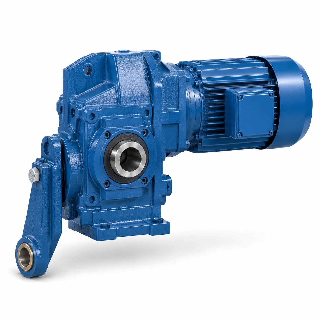
Request the rated performance boundary from the exact proposed configuration; compare drive options at the same speed, load and mounting conditions; an attractive ratio alone cannot establish suitability for continuous or intermittent operation.
Define intermittent duty precisely
An indexing machine may run briefly yet repeat hundreds of start-stop actions in one shift; frequent motor acceleration can create peak gear loading even if average energy use seems modest.
Counting operating minutes without the number of starts understates transient demand; measure starts per hour, acceleration ramp and dwell duration for each recipe.
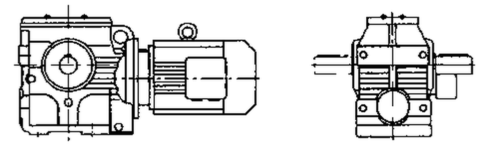
Prepare a cycle diagram identifying worst-case loaded starts and braking events; confirm mechanical and thermal limits for the actual time sequence; two machines with equal daily run time may impose radically different duty.
Analyze sliding-friction heat
Worm gears normally contain significant sliding contact with consequent power loss; a sealed, compact machine cabinet may accumulate heat during repeated operation.
No-load smoothness does not prove thermal capacity after extended production; supply duty factor, ambient temperature and enclosure airflow details.
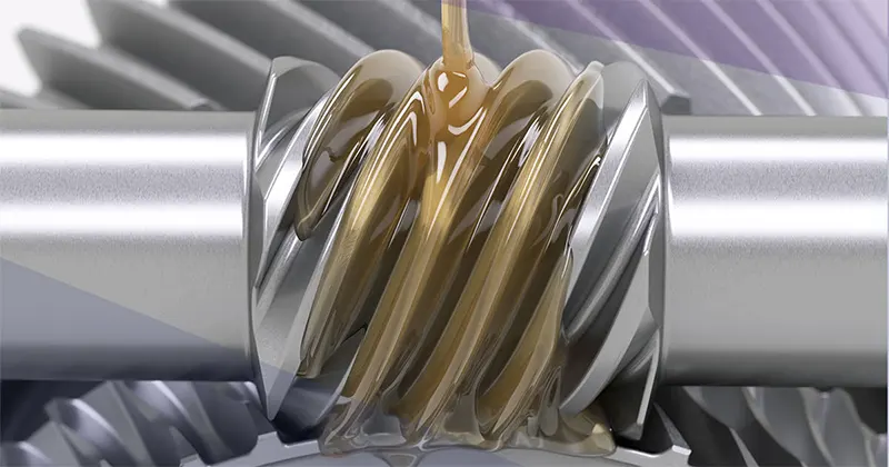
Request maker temperature-rise assumptions and approved lubrication for the model; thermal confirmation should address the intended cycle, not just continuous nameplate power; overheating may emerge after many cycles rather than the first test.
Avoid assuming self-locking safety
Backdriving resistance depends on friction, lead angle, wear, load and lubrication; an elevated actuator may reverse under gravity even if the unloaded worm feels resistant.
Treating worm friction as a load-holding device can create a machine-safety hazard; define worst-case reverse torque and required response when power disappears.
Obtain a separate safety system assessment and selected holding brake rating; approve holding only with an engineered, tested brake and control function; a gearbox cannot be presented as a certified hoist brake without specific evidence.
Specify the output support scheme
Hollow shaft and flange arrangements change connection and housing reaction details; an unsupported long shaft can exert radial or axial loads on reducer bearings.
A small compact casing provides no evidence of allowable overhung load; measure shaft fit, bearing span, load application point and support locations.
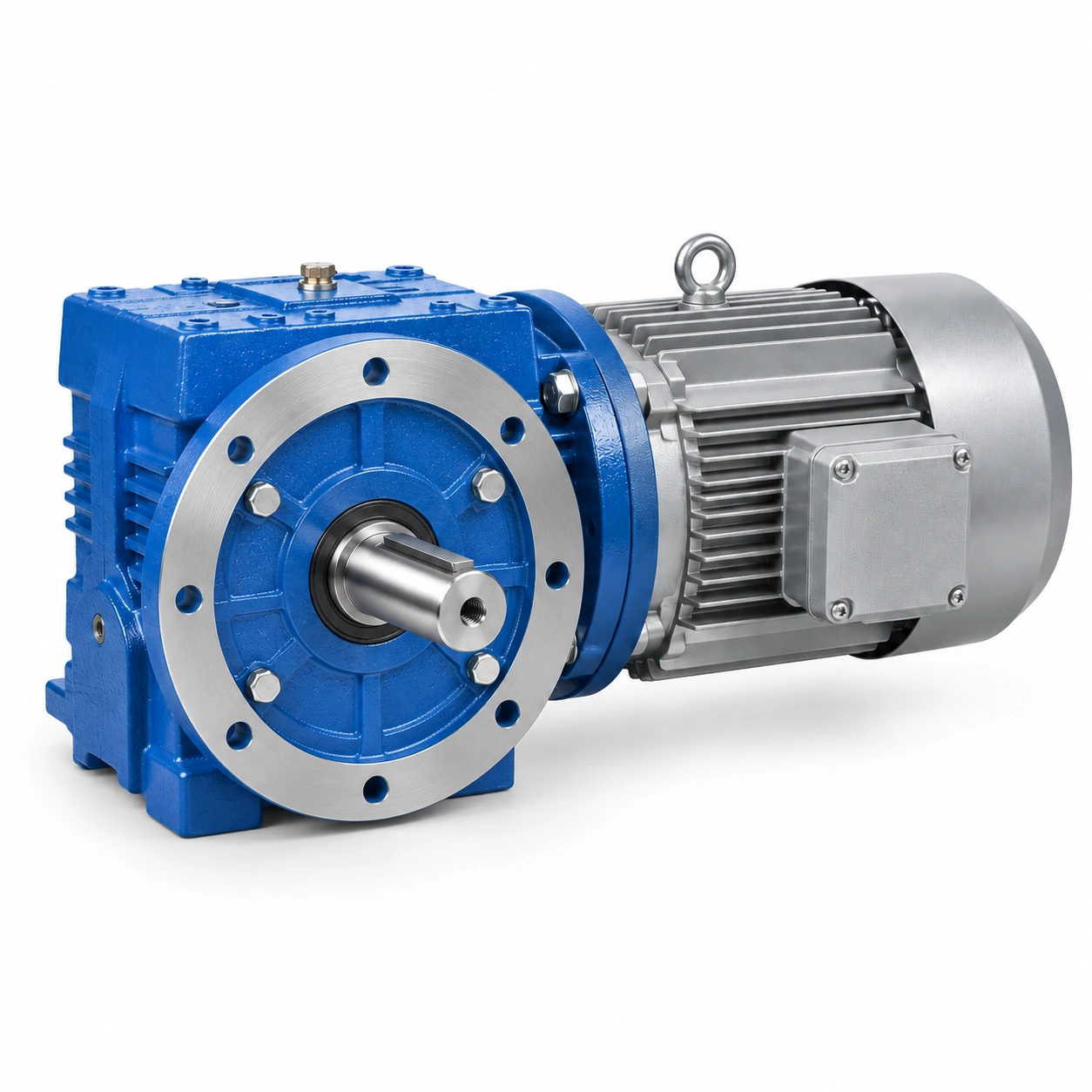
Request external Fr and Fa limits for the actual shaft position and operating speed; clear the complete assembly support design with the responsible engineer; selecting solely on transmitted torque ignores the failure mode of output bearings.
An unsupported long shaft can exert radial or axial loads on reducer bearings. A small compact casing provides no evidence of allowable overhung load. Examine the S-series intermittent worm drives layout example. Request external Fr and Fa limits for the actual shaft position and operating speed. Clear the complete assembly support design with the responsible engineer.
Check lubricant compatibility
Sliding gear contact may have different lubricant requirements than a pure helical train; mixing an unapproved oil with an existing fill can change additive behavior and seal performance.
Using whichever grade is available in the plant is not a sound service method; identify the exact approved lubricant formulation and application temperature.
Keep supplier oil-fill data and any incompatibility restrictions in the service record; release the maintenance plan against the maker instructions; an unspecified gear oil interval cannot be made universal across S-series sizes.
Match the requested mounting orientation
Gearmesh position and bearing support can change relative to the oil surface with a rotated housing; a side-mounted machine might need a variant fill level or breather arrangement.
Using a horizontal factory shipping orientation as the installed configuration can starve bearings; mark shaft directions and fill or drain access on the installation sketch.
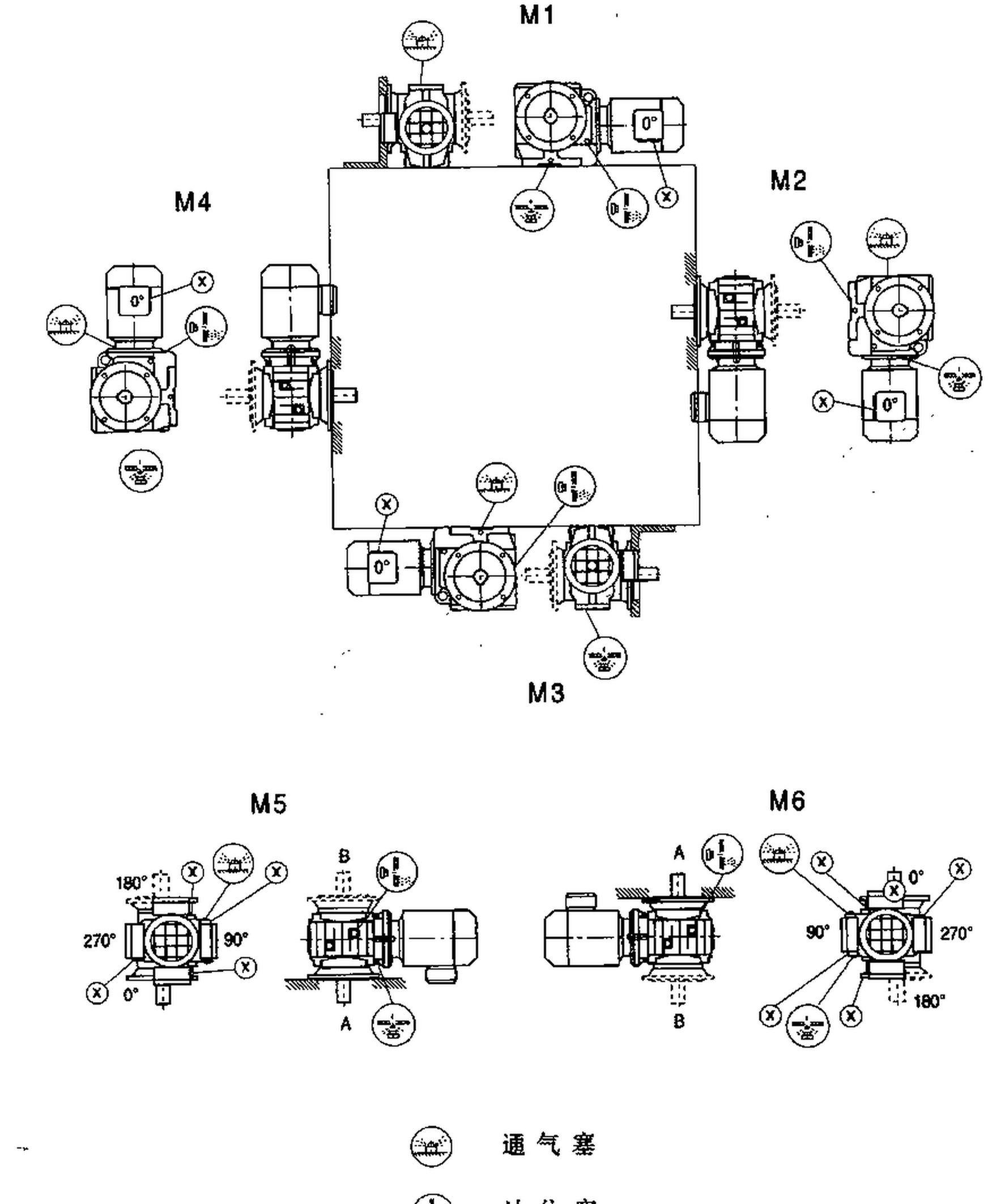
Obtain manufacturer guidance for the precise installation code; use an approved mounting orientation with a practical fill and check method; a small machine enclosure is not a justification for improvising oil placement.
Verify emergency and maintenance modes
Low-frequency jogging, emergency return and handwheel operation may challenge a chosen drive; a technician could move the output manually with motor isolated under a different load path.
Unexpected backdriving or trapped energy changes the safety assessment; identify all operating and isolation modes including maintenance access.
Document reverse motion rules, brake release and torque path for each mode; complete the machine-level risk assessment before production release; a reducer proven in normal cycling may still be inappropriate for an emergency state.
Illustrative engineering scenario: Intermittent indexing, positioning and conveying machinery
An automatic indexing table moves product carriers a short distance, pauses for a handling operation and repeats the sequence. An S-series helical-worm unit looks like a reasonable compact drive candidate. However, the design calculation must represent the acceleration and stopping events rather than treating the intermittent motor-on time as the only load. The engineer records the heaviest product carrier, cycle rate, dwell duration, load inertia and the number of reversals. This identifies mechanical peak loading that may occur far above the average demand over a shift.
Suppose the machine can be pushed backward when a guard is open for maintenance. It would be unsafe to decide that worm friction will hold the mechanism merely because the output feels stiff during a short manual check. Gear geometry, surface condition and lubrication can change backdrive behavior. If a held position protects a worker or an elevated mass, the holding function needs a separately engineered and validated brake or equivalent safety system. The gearbox itself remains responsible for transmitting motion within its documented rating; a holding brake has to be sized for the real load and fault cases, not an assumed static fraction of motor torque.
A second issue appears when the system is installed inside a sealed cabinet. Sliding losses can accumulate heat through repeated cycles, even though each individual movement is short. The request for quotation should therefore include the cycle diagram, expected cabinet temperature, mounting position and lubricant plan. During initial production, record a temperature trend over a representative run and inspect the system under controlled reversals. If the supplier returns a mechanical rating but no relevant thermal basis or output-force limit, those unknowns remain explicit before production approval rather than being hidden behind the appealingly compact housing.
Five-stage review for intermittent indexing, positioning and conveying machinery
-
Separate gear stages in the power pathIdentify input rpm, output rpm, ratio and operating-point efficiency evidence. Compare drive options at the same speed, load and mounting conditions.
-
Define intermittent duty preciselyPrepare a cycle diagram identifying worst-case loaded starts and braking events. Two machines with equal daily run time may impose radically different duty.
-
Avoid assuming self-locking safetyDefine worst-case reverse torque and required response when power disappears. Approve holding only with an engineered, tested brake and control function.
-
Check lubricant compatibilityKeep supplier oil-fill data and any incompatibility restrictions in the service record. An unspecified gear oil interval cannot be made universal across S-series sizes.
-
Verify emergency and maintenance modesIdentify all operating and isolation modes including maintenance access. Complete the machine-level risk assessment before production release.
Engineering comparison matrix: S series helical worm reducer intermittent duty
| Engineering question | Evidence to collect | Review decision |
|---|---|---|
| Separate gear stages in the power path | Request the rated performance boundary from the exact proposed configuration. | Compare drive options at the same speed, load and mounting conditions. |
| Define intermittent duty precisely | Prepare a cycle diagram identifying worst-case loaded starts and braking events. | Confirm mechanical and thermal limits for the actual time sequence. |
| Analyze sliding-friction heat | Request maker temperature-rise assumptions and approved lubrication for the model. | Thermal confirmation should address the intended cycle, not just continuous nameplate power. |
| Avoid assuming self-locking safety | Obtain a separate safety system assessment and selected holding brake rating. | Approve holding only with an engineered, tested brake and control function. |
| Specify the output support scheme | Request external Fr and Fa limits for the actual shaft position and operating speed. | Clear the complete assembly support design with the responsible engineer. |
| Check lubricant compatibility | Keep supplier oil-fill data and any incompatibility restrictions in the service record. | Release the maintenance plan against the maker instructions. |
Frequently Asked Questions
Will a helical-worm reducer hold a load when motor power is removed?
Does low average running time guarantee cool operation?
Which torque figures matter for intermittent indexing?
How should the output connection be specified?
What makes a final review credible for intermittent indexing, positioning and conveying machinery?
A side-mounted machine might need a variant fill level or breather arrangement. When comparing actual mounting geometry, use the S-series intermittent worm drives configuration options. Obtain manufacturer guidance for the precise installation code.
Identify all operating and isolation modes including maintenance access. For an engineering quotation that records the open conditions, contact the technical team about S-series intermittent worm drives. Complete the machine-level risk assessment before production release.
Engineering sources for S-Series Helical-Worm Gearbox for Intermittent Machinery
For the s-series helical-worm gearbox for intermittent machinery workflow, consult these reference documents alongside the actual model installation manual:
- S-Series Helical-Worm Gearbox for Intermittent Machinery: SEW-EURODRIVE, Lubricant tables (analysis).
- S-Series Helical-Worm Gearbox for Intermittent Machinery: SEW-EURODRIVE, Application-specific service factor (interface review).
- S-Series Helical-Worm Gearbox for Intermittent Machinery: SEW-EURODRIVE, Change of mounting position (acceptance checks).