
A foot-mounted R gearmotor and an RF flange assembly may share the same powertrain idea but load their support structure differently. Oversized bolts do not compensate for a flexible or uneven structural support. Refer to the R-series foot and flange mounting guidance. Mark foot pad contact, center height and any permitted shim arrangement on the assembly drawing. A fitting report must confirm pilot engagement and allowable support arrangement.
Locate a flange by its pilot
Plan terminal-box and fan space
Freeze the ordered structural version
Understand the load path through feet
R foot mounting reacts torque and weight through a base and its fasteners; a thin plate welded to a machine frame can bend enough to affect shaft alignment at operating torque.
Oversized bolts do not compensate for a flexible or uneven structural support; inspect base plate flatness, weldment stiffness and bolt positions at the installed load.
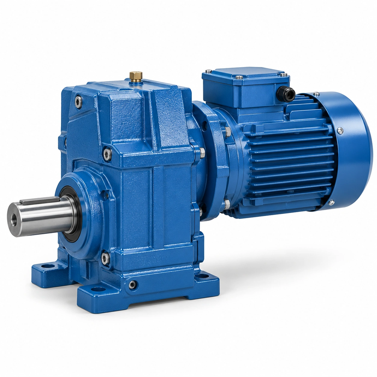
Mark foot pad contact, center height and any permitted shim arrangement on the assembly drawing; release mounting only after foundation support and permitted bolt stresses have been checked; poor load transfer can shorten bearing or coupling life despite a correct gear ratio.
Locate a flange by its pilot
An RF flange can establish the gearbox position through a machined register and bolt circle; a hole pattern that appears similar may conceal a different pilot diameter, shoulder or flange thickness.
Accepting a flange from bolt count alone risks misalignment or failure to fit; measure flange pilot, bolt circle, fastener size and clear mounting depth.
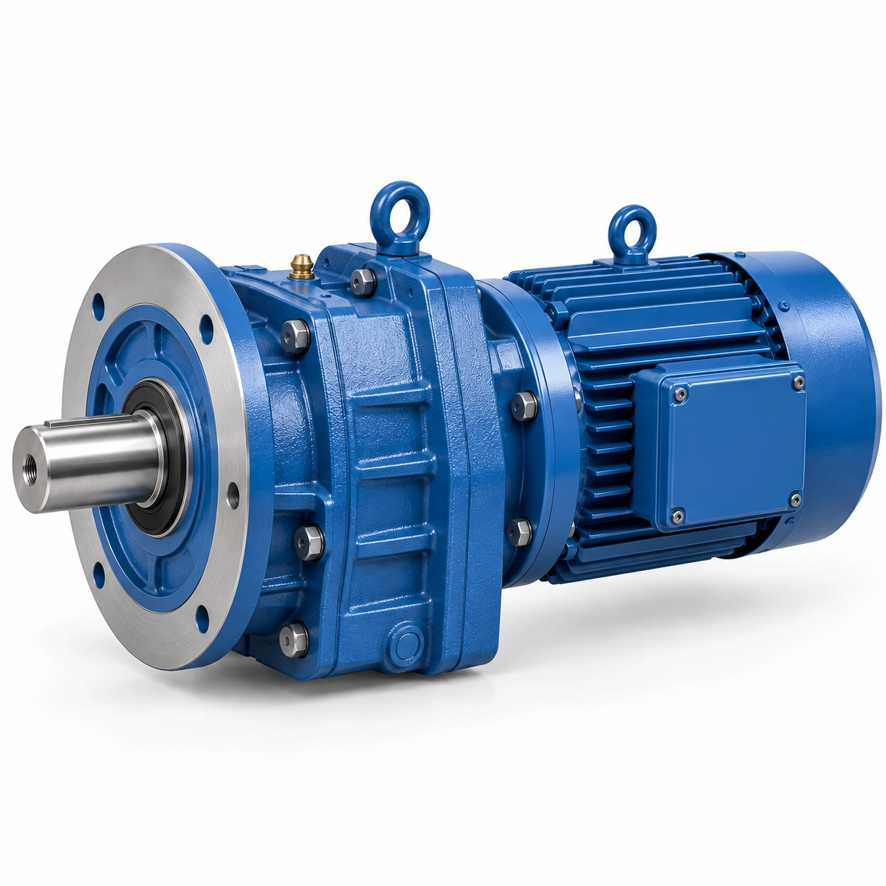
Compare toleranced dimensional drawings rather than a catalog thumbnail or photo; a fitting report must confirm pilot engagement and allowable support arrangement; an extra washer or enlarged hole is not an engineering equivalence assessment.
Keep the input-output centerline explicit
Coaxial arrangements align the driven axis with the geared-motor package along the same nominal line; a replacement motor adapter can change overall package length even when the output diameter is unchanged.
An unnoticed length increase can prevent guard installation or motor extraction; overlay the R and RF approved envelopes on a full machine assembly view.
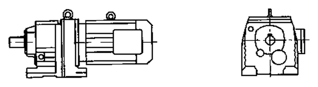
Dimension center height, shaft projection and access from the rear of the motor; select a variant that clears the structure across its full service movement; an attractive short gearbox housing may still produce an excessively long assembly.
Check base and flange orientation
Orientation affects oil distribution, sealing and the accessibility of oil-level features; changing from a base-mounted horizontal unit to a vertically supported flange may place bearings at different oil levels.
A fill quantity copied from another mounting position can lead to inadequate lubrication; state input axis direction, output axis direction and location of the breather on the drawing.
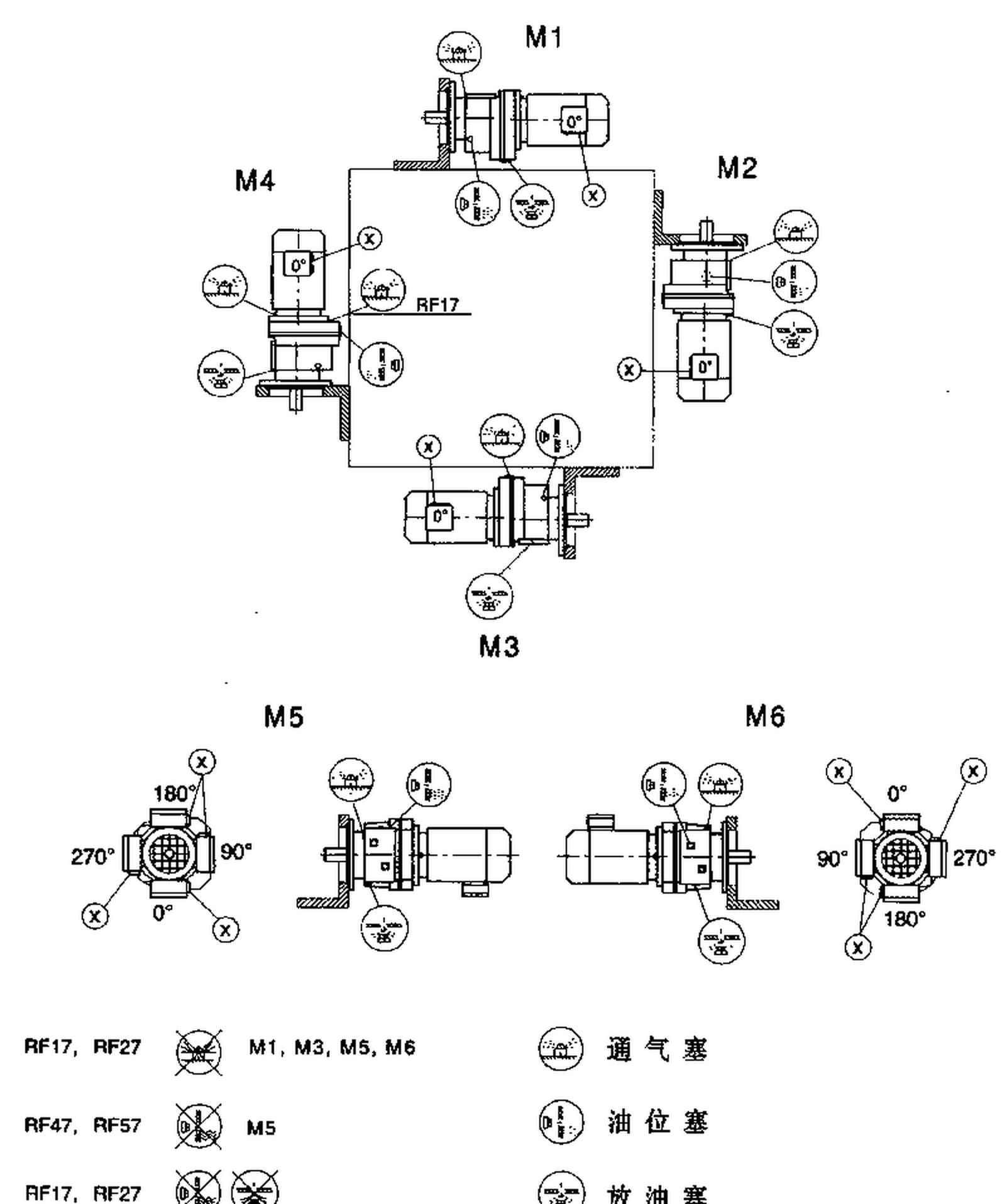
Obtain the maker approved lubricant and oil level for that exact installation position; operating approval should cite the supported mounting code and fill instructions; a correct bolt pattern is not a permit to operate in any spatial orientation.
Plan terminal-box and fan space
The geared motor must clear electrical conduits, ventilation pathways and tools for removal; an RF assembly placed against a vessel wall may limit access to the motor terminal box.
An installation that can be bolted together may still be unserviceable; check motor frame, terminal-box rotation and fan-end clearance with the actual motor.
Document lifting points and cable bend radius constraints in the machine layout; accept only a configuration with usable operating and maintenance clearances; restricted airflow or inability to isolate power complicates routine service.
An RF assembly placed against a vessel wall may limit access to the motor terminal box. An installation that can be bolted together may still be unserviceable. Examine the R-series foot and flange mounting layout example. Document lifting points and cable bend radius constraints in the machine layout. Accept only a configuration with usable operating and maintenance clearances.
Review coupling tolerance and runout
An inline motor gearbox often uses a flexible coupling to the driven machine shaft; angular misalignment and shaft runout can combine with thermal expansion during long shifts.
Using a flexible element as a cure for a skewed base increases bearing reactions; measure alignment at the coupling reference planes after all mechanical fastening.
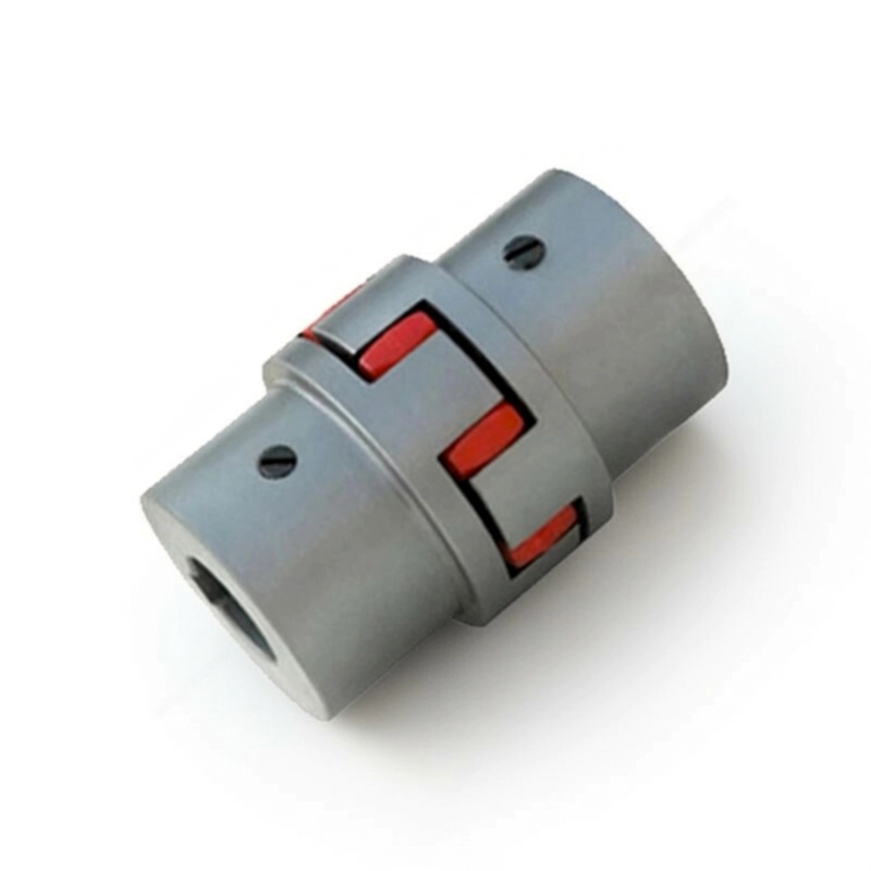
Keep tolerance information for the actual coupling make and size beside the results; the as-left readings should meet equipment-specific alignment limits; shaft centerlines seen in a CAD rendering are not proof of installed alignment.
Compare reaction under reversals
Short-cycle machinery may reverse before a motor or drive reaches steady temperature; changing the supporting geometry can alter which fasteners and welds see reversing force.
Assuming equal nominal power means equal foundation reaction can miss fatigue loading; map torque direction and acceleration events for forward and reverse operating states.
Check support points against the maximum applicable machine torque and duty; the machine designer must approve the complete load case at each mount; cracked brackets or loosening bolts may be symptoms of a structural mismatch.
Freeze the ordered structural version
Model suffixes can indicate motor adaptation, flange type, hollow or solid outputs and accessories; two R-series quotations with different shaft or flange parts are not identical supply scopes.
A missing drawing revision can turn a suitable selection into a wrong-order return; request the full model code and a dimensioned general arrangement from each bidder.
Cross-check foot holes, flange pilot, output shaft and lubrication in the purchase order; final acceptance should reference the signed interface drawing and variant code; a purchasing description that says only inline helical gearbox is insufficient.
Illustrative engineering scenario: An inline drive mounted on an oem machine frame
Imagine an OEM replacing a worn inline gearmotor mounted under a filling machine. The current assembly uses four feet bolted to a fabricated steel base. Procurement receives an alternative described as an RF flange model with an equivalent nominal ratio. The alternative looks attractive because the flange appears to save base space. Before it is ordered, the designer discovers that the existing output coupling centerline is established by a fixed support bracket; the centerline cannot move without reworking the driven shaft. A flange pilot must therefore be checked in a dimensioned section view, not matched to a photograph.
A useful comparison drawing shows the base footprint and bolt spacing of the original R-type arrangement beside the pilot diameter, flange thickness, bolt circle and shaft projection of the proposed RF. The drawing also includes the real motor envelope, cable-exit direction and maintenance withdrawal path. If a designer chooses the flange version, the surrounding plate needs sufficient stiffness to carry reaction loads without moving the shaft centerline. This is a structural design decision. Merely drilling new bolt holes does not establish that the mounting plate can perform the same function as a machined foot-supported foundation.
The oil question is checked separately. A change in mounting face can change where the reducer bearings sit relative to the lubrication system, so the exact allowed installation position must appear in the technical submission. During factory acceptance or site commissioning, inspect the coupling alignment after final bolt torque, and verify the installed level and breather position. The resulting recommendation may be to retain the foot version, redesign the supporting flange or select a different body size. Each is a legitimate engineering outcome. The unacceptable outcome is an undocumented assertion that the two structural variants are interchangeable merely because they share a family name.
Five-stage review for an inline drive mounted on an OEM machine frame
-
Understand the load path through feetInspect base plate flatness, weldment stiffness and bolt positions at the installed load. Release mounting only after foundation support and permitted bolt stresses have been checked.
-
Locate a flange by its pilotCompare toleranced dimensional drawings rather than a catalog thumbnail or photo. An extra washer or enlarged hole is not an engineering equivalence assessment.
-
Check base and flange orientationState input axis direction, output axis direction and location of the breather on the drawing. Operating approval should cite the supported mounting code and fill instructions.
-
Review coupling tolerance and runoutKeep tolerance information for the actual coupling make and size beside the results. Shaft centerlines seen in a CAD rendering are not proof of installed alignment.
-
Freeze the ordered structural versionRequest the full model code and a dimensioned general arrangement from each bidder. Final acceptance should reference the signed interface drawing and variant code.
Engineering comparison matrix: R series helical gearmotor foot flange comparison
| Engineering question | Evidence to collect | Review decision |
|---|---|---|
| Understand the load path through feet | Mark foot pad contact, center height and any permitted shim arrangement on the assembly drawing. | Release mounting only after foundation support and permitted bolt stresses have been checked. |
| Locate a flange by its pilot | Compare toleranced dimensional drawings rather than a catalog thumbnail or photo. | A fitting report must confirm pilot engagement and allowable support arrangement. |
| Keep the input-output centerline explicit | Dimension center height, shaft projection and access from the rear of the motor. | Select a variant that clears the structure across its full service movement. |
| Check base and flange orientation | Obtain the maker approved lubricant and oil level for that exact installation position. | Operating approval should cite the supported mounting code and fill instructions. |
| Plan terminal-box and fan space | Document lifting points and cable bend radius constraints in the machine layout. | Accept only a configuration with usable operating and maintenance clearances. |
| Review coupling tolerance and runout | Keep tolerance information for the actual coupling make and size beside the results. | The as-left readings should meet equipment-specific alignment limits. |
Frequently Asked Questions
Can an RF flange variant replace an R foot-mount without changing the frame?
What measurement prevents most mounting surprises?
Why must the oil instruction be rechecked for a flange-mounted gearbox?
Is the shorter-looking gearmotor the best choice for a confined machine?
What makes a final review credible for an inline drive mounted on an OEM machine frame?
Changing the supporting geometry can alter which fasteners and welds see reversing force. When comparing actual mounting geometry, use the R-series foot and flange mounting configuration options. Check support points against the maximum applicable machine torque and duty.
Request the full model code and a dimensioned general arrangement from each bidder. For an engineering quotation that records the open conditions, contact the technical team about R-series foot and flange mounting. Final acceptance should reference the signed interface drawing and variant code.
Engineering sources for R-Series Inline Helical Gearmotor — Foot or Flange Mounting
For the r-series inline helical gearmotor: foot or flange mounting workflow, consult these reference documents alongside the actual model installation manual:
- R-Series Inline Helical Gearmotor: Foot or Flange Mounting: SEW-EURODRIVE, Dimension sheet information (analysis).
- R-Series Inline Helical Gearmotor: Foot or Flange Mounting: SEW-EURODRIVE, Change of mounting position (interface review).
- R-Series Inline Helical Gearmotor: Foot or Flange Mounting: SEW-EURODRIVE, Basic calculation process (acceptance checks).