
A torque value states rotational transmission but does not by itself describe permitted bending or thrust loads. Large torque capacity cannot establish radial-load permission. Refer to the radial and axial shaft loads guidance. Record shaft length and radial force direction relative to supports. Verify radial load at the actual shaft support and lever arm.
Calculate pulley force from real tensions
Understand bearing life assumptions
Put Fr and Fa on the drawing
Separate rotational and transverse demand
A shaft may transmit torque yet be bent by a sprocket or belt force; external bending depends on force location and bearing geometry.
Large torque capacity cannot establish radial-load permission; draw a free-body diagram showing torque and radial forces.
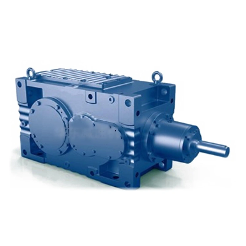
Record shaft length and radial force direction relative to supports; check each demand against its corresponding manufacturer rating; a mechanically strong gear mesh does not prevent an overloaded output bearing.
Calculate pulley force from real tensions
A belt pulley sees the vector resultant of tight-side and slack-side belt forces; the belt force relevant to shaft bending differs from effective tangential driving force.
Using only transmitted torque to estimate bearing load can be wrong; collect belt geometry and both span tensions or accepted design estimates.

Compute the force vector in the bearing coordinate system; verify radial load at the actual shaft support and lever arm; belt pretension can increase shaft load without increasing useful transmitted power.
Define the lever arm
A point load farther outboard produces larger bending moment at the supporting bearing; moving a sprocket outward by a spacer can materially change shaft stress.
An OEM allowable Fr may assume an application point unlike the machine; dimension distance from specified bearing datum to load center.
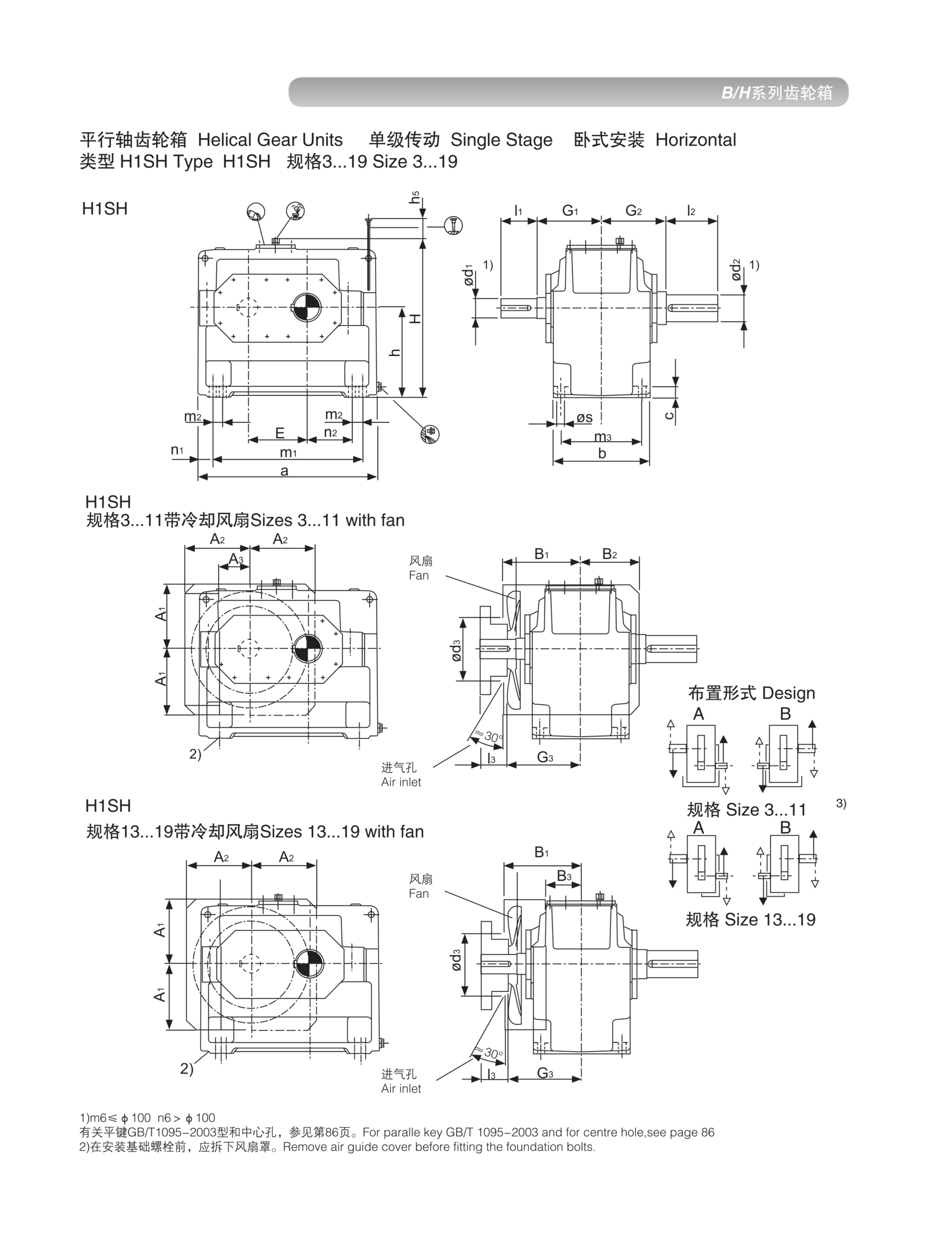
Mark the reference point used in the supplier load graph; use the rating for the same application location; a quoted load without lever-arm definition is incomplete.
Record axial load direction
Augers, screw conveyors and driven couplings may transmit thrust to the output; axial load direction can reverse with process changes or gear rotation.
A single absolute Fa number may not characterize both thrust directions; define signs and extreme axial forces under running and jam states.
Document output speed and any simultaneous radial component; request combined-load allowance from the selected unit manufacturer; ignoring thrust can cause bearing damage even when torque is modest.
Understand bearing life assumptions
Published permissible load can depend on rpm and target bearing service life; a slow occasional actuator and a nonstop conveyor have different cumulative duty.
A load figure without life basis cannot be applied blindly; specify operating hours and shaft speed along with load cases.
Obtain source rating notes that explain life and reliability assumptions; accept a bearing arrangement only for an agreed life and duty basis; passing a static-force check does not establish long-term rolling fatigue life.
A slow occasional actuator and a nonstop conveyor have different cumulative duty. A load figure without life basis cannot be applied blindly. Examine the radial and axial shaft loads layout example. Obtain source rating notes that explain life and reliability assumptions. Accept a bearing arrangement only for an agreed life and duty basis.
Consider independent shaft supports
Separate bearings can transfer process forces into the machine rather than gearbox output; a conveyor drum may benefit from its own pedestal bearings and a torque-only coupling.
Adding extra fixed supports without alignment design can overconstrain the shaft; review support locations, thermal movement and coupling alignment.
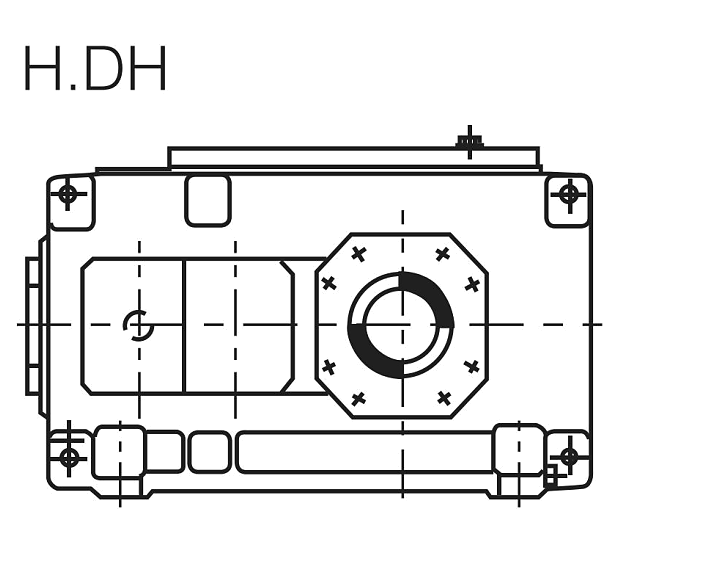
Document which bearing locates the shaft axially and which floats; approve a support system with an intentional load path; a second bearing block can harm reliability if its degrees of freedom conflict.
Check shaft and key stress
The output interface transmits torque through a key, spline or clamping connection; combined bending and twisting create stress not reflected in a single torque number.
Nominal key width does not prove adequate engagement or surface pressure; provide shaft diameter, key length, fillets and material where known.
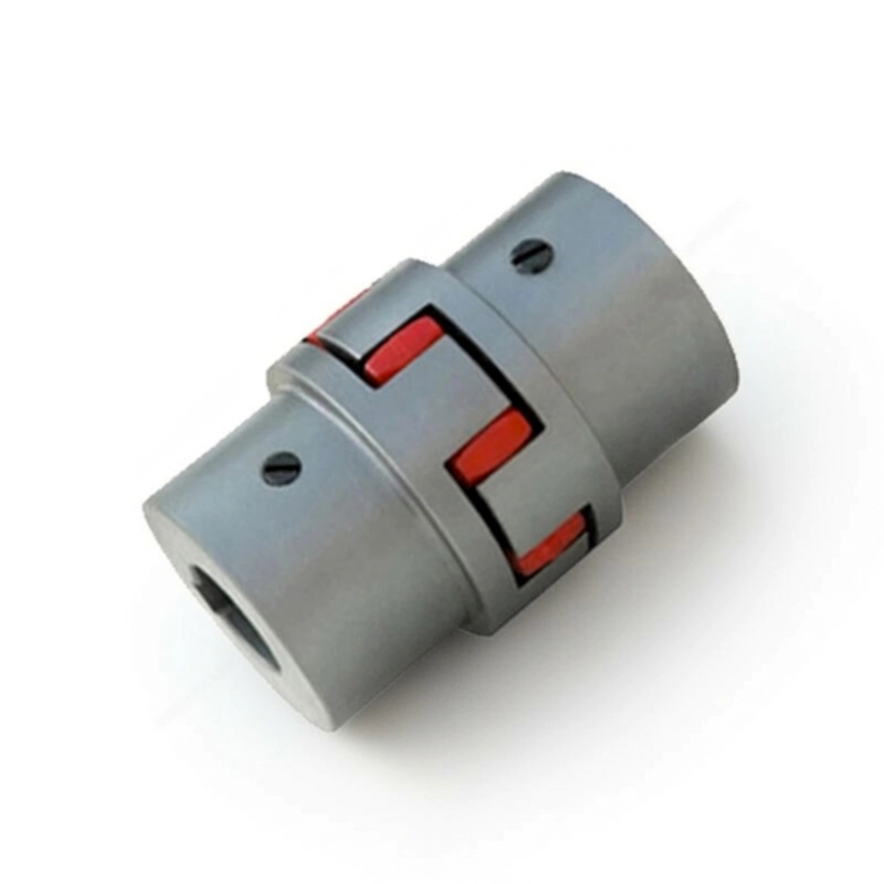
Request coupling or shaft connection approval from responsible designers; use a confirmed connection design rather than visual resemblance; a perfectly rated gearbox is useless if the machine shaft interface fails.
Put Fr and Fa on the drawing
A production drawing should say whether force limits are allowed and under which conditions; a label without reference distance or speed can be mistaken for a universal guarantee.
Technicians may later move a pulley without knowing the bearing implication; ask for indicated force positions, shaft speeds and life conditions.
Link approved force limits to the exact assembly revision; release only a drawing with unambiguous engineering constraints; the same numerical load can mean something different after a support change.
Illustrative engineering scenario: An output shaft supporting a pulley, auger or external load
Consider a belt-driven auxiliary machine with a sprocket mounted on the protruding reducer output. The motor and ratio calculation indicates enough nominal torque for the process, so an early procurement comparison lists both candidate gearboxes as acceptable. The mechanical reviewer notices that the output sprocket sits well outside the gearbox support bearing. Transmitted torque may be calculated from effective tangential drive force, but bearing radial load also includes other tension components. Those forces act through a lever arm that creates bending moment. It is therefore insufficient to compare a torque figure in N m with a radial bearing force limit in N; they describe different physical demands.
The team marks the center of the sprocket on a shaft section and records its distance to the bearing reference specified by each supplier. The pulley or sprocket force direction is shown in machine coordinates, and any process thrust is defined separately along the shaft. The bearing-life requirement is expressed in operating hours at the expected output rpm. The manufacturer can then determine whether its quoted allowable Fr and Fa cover the simultaneous conditions. If one design provides only a radial force number without speed, lever arm or thrust assumptions, the team records the information as missing rather than treating the higher number as the better design.
One possible alternative is to place an independent bearing block beside the machine shaft and use a flexible coupling for torque transfer from the reducer. That may reduce external gearbox bearing load, but the support system must be designed so shafts can align and expand thermally. Two fixed bearing locations introduced without considering constraint can create a new failure mode. The accepted solution is whatever complete support arrangement is evidenced and reviewed, not simply the gearbox with the largest nominal torque.
If the external drive uses two belt spans, measuring only the effective difference between their tensions will describe useful torque but not necessarily the radial bearing load. The latter depends on the vector sum of both span forces. That distinction matters when pretension is high. The engineer should keep force vectors and load application distance together on the drawing, with the signed manufacturer response attached. A later belt retensioning procedure must not silently exceed the reviewed bearing force envelope.
Five-stage review for an output shaft supporting a pulley, auger or external load
-
Separate rotational and transverse demandDraw a free-body diagram showing torque and radial forces. Check each demand against its corresponding manufacturer rating.
-
Calculate pulley force from real tensionsCompute the force vector in the bearing coordinate system. Belt pretension can increase shaft load without increasing useful transmitted power.
-
Record axial load directionDefine signs and extreme axial forces under running and jam states. Request combined-load allowance from the selected unit manufacturer.
-
Consider independent shaft supportsDocument which bearing locates the shaft axially and which floats. A second bearing block can harm reliability if its degrees of freedom conflict.
-
Put Fr and Fa on the drawingAsk for indicated force positions, shaft speeds and life conditions. Release only a drawing with unambiguous engineering constraints.
Engineering comparison matrix: helical gearbox radial axial output shaft load
| Engineering question | Evidence to collect | Review decision |
|---|---|---|
| Separate rotational and transverse demand | Record shaft length and radial force direction relative to supports. | Check each demand against its corresponding manufacturer rating. |
| Calculate pulley force from real tensions | Compute the force vector in the bearing coordinate system. | Verify radial load at the actual shaft support and lever arm. |
| Define the lever arm | Mark the reference point used in the supplier load graph. | Use the rating for the same application location. |
| Record axial load direction | Document output speed and any simultaneous radial component. | Request combined-load allowance from the selected unit manufacturer. |
| Understand bearing life assumptions | Obtain source rating notes that explain life and reliability assumptions. | Accept a bearing arrangement only for an agreed life and duty basis. |
| Consider independent shaft supports | Document which bearing locates the shaft axially and which floats. | Approve a support system with an intentional load path. |
Frequently Asked Questions
Are rated torque and allowable radial load interchangeable?
Why is sprocket or pulley position important?
What is the difference between belt pull and shaft side force?
When does an external bearing support help?
What makes a final review credible for an output shaft supporting a pulley, auger or external load?
Combined bending and twisting create stress not reflected in a single torque number. When comparing actual mounting geometry, use the radial and axial shaft loads configuration options. Request coupling or shaft connection approval from responsible designers.
Ask for indicated force positions, shaft speeds and life conditions. For an engineering quotation that records the open conditions, contact the technical team about radial and axial shaft loads. Release only a drawing with unambiguous engineering constraints.
Engineering sources for Helical Gearbox Radial and Axial Shaft Loads Explained
For the helical gearbox radial and axial shaft loads explained workflow, consult these reference documents alongside the actual model installation manual:
- Helical Gearbox Radial and Axial Shaft Loads Explained: SKF, Bearing App documentation (analysis).
- Helical Gearbox Radial and Axial Shaft Loads Explained: SEW-EURODRIVE, Dimension sheet information (interface review).
- Helical Gearbox Radial and Axial Shaft Loads Explained: SEW-EURODRIVE, Basic calculation process (acceptance checks).